
English Manual
Page 1
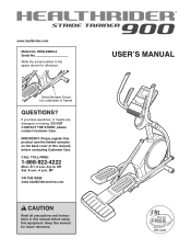
... register this product (see the limited warranty on underside of this equipment. MT Sat. 8 a.m.-4 p.m. Serial Number Decal (on the back cover of frame) QUESTIONS? Keep this manual for reference. CALL TOLL-FREE: 1-888-922-4222 Mon.-Fri. 6 a.m.-6 p.m. USERʼS MANUAL Write the serial number in this manual before using this manual) before contacting Customer Care. please contact Customer Care. www.healthrider.com Model No. HREL59809.4 Serial No.
... register this product (see the limited warranty on underside of this equipment. MT Sat. 8 a.m.-4 p.m. Serial Number Decal (on the back cover of frame) QUESTIONS? Keep this manual for reference. CALL TOLL-FREE: 1-888-922-4222 Mon.-Fri. 6 a.m.-6 p.m. USERʼS MANUAL Write the serial number in this manual before using this manual) before contacting Customer Care. please contact Customer Care. www.healthrider.com Model No. HREL59809.4 Serial No.
English Manual
Page 2
... at actual size. HEALTHRIDER is missing or illegible, see the front cover of ICON IP, Inc. 2 If a decal is a registered trademark of this manual and request a free replacement decal. TABLE OF CONTENTS WARNING DECAL PLACEMENT 2 IMPORTANT PRECAUTIONS 3 BEFORE YOU BEGIN 4 ASSEMBLY 5 HOW TO USE THE ELLIPTICAL 13 MAINTENANCE AND TROUBLESHOOTING 20 EXERCISE GUIDELINES 22 PART LIST 23 EXPLODED DRAWING 25 ORDERING REPLACEMENT PARTS Back Cover LIMITED WARRANTY Back Cover WARNING DECAL...
... at actual size. HEALTHRIDER is missing or illegible, see the front cover of ICON IP, Inc. 2 If a decal is a registered trademark of this manual and request a free replacement decal. TABLE OF CONTENTS WARNING DECAL PLACEMENT 2 IMPORTANT PRECAUTIONS 3 BEFORE YOU BEGIN 4 ASSEMBLY 5 HOW TO USE THE ELLIPTICAL 13 MAINTENANCE AND TROUBLESHOOTING 20 EXERCISE GUIDELINES 22 PART LIST 23 EXPLODED DRAWING 25 ORDERING REPLACEMENT PARTS Back Cover LIMITED WARRANTY Back Cover WARNING DECAL...
English Manual
Page 3
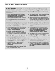
... pulse sensor is the responsibility of the elliptical and 2 ft. (0.6 m) on the elliptical. Keep your physician. Do not use only. Inspect and properly tighten all parts regularly. do not arch your pedaling speed in a garage or covered patio, or near water. 6. Place the elliptical on a level surface, with pre-existing health problems. 2. The elliptical should not be used by or through the use of heart rate readings. Over exercising...
... pulse sensor is the responsibility of the elliptical and 2 ft. (0.6 m) on the elliptical. Keep your physician. Do not use only. Inspect and properly tighten all parts regularly. do not arch your pedaling speed in a garage or covered patio, or near water. 6. Place the elliptical on a level surface, with pre-existing health problems. 2. The elliptical should not be used by or through the use of heart rate readings. Over exercising...
English Manual
Page 4
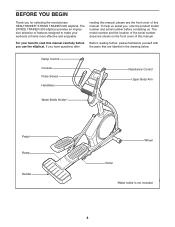
... parts that are shown on the front cover of the serial number decal are labeled in the drawing below. For your workouts at home more effective and enjoyable. If you , note the product model number and serial number before Before reading further, please familiarize yourself with you for selecting the revolutionary HEALTHRIDER® STRIDE TRAINER 900 elliptical. reading this manual. Ramp Control Console Pulse Sensor Handlebar Resistance Control Upper Body Arm Water Bottle Holder* Pedal...
... parts that are shown on the front cover of the serial number decal are labeled in the drawing below. For your workouts at home more effective and enjoyable. If you , note the product model number and serial number before Before reading further, please familiarize yourself with you for selecting the revolutionary HEALTHRIDER® STRIDE TRAINER 900 elliptical. reading this manual. Ramp Control Console Pulse Sensor Handlebar Resistance Control Upper Body Arm Water Bottle Holder* Pedal...
English Manual
Page 5
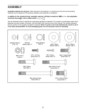
... x 12.7mm Screw (59)-12 M4 x 16mm Screw (104)-10 M8 x 19mm Patch Screw (82)-15 M8 x 38mm Bolt (96)-4 M8 x 56mm Patch Screw (94)-2 M8 x 80mm Patch Screw (84)-2 M10 x 20mm Patch Screw (66)-2 5 Note: If a part is the key number of the part, from the PART LIST near the end of this manual. To avoid damaging parts, do not use power tools for assembly. In addition...
... x 12.7mm Screw (59)-12 M4 x 16mm Screw (104)-10 M8 x 19mm Patch Screw (82)-15 M8 x 38mm Bolt (96)-4 M8 x 56mm Patch Screw (94)-2 M8 x 80mm Patch Screw (84)-2 M10 x 20mm Patch Screw (66)-2 5 Note: If a part is the key number of the part, from the PART LIST near the end of this manual. To avoid damaging parts, do not use power tools for assembly. In addition...

English Manual
Page 10
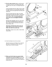
... wires downward into the Rear Upright Cover (80). 4 80 10 Connect the wires on the wires. Make sure to connect the console wire that has a tag to the Upright (4) with two M4 x 16mm Screws (104). 104 4 80 11. Attach the Console (7) to the Control Wire that has a tag. Orient the Rear Upright Cover (80) as shown. 11 Attach the Front Upright Cover (91) around the Upright (4) by pressing the tabs on the Front 91 Upright Cover...
... wires downward into the Rear Upright Cover (80). 4 80 10 Connect the wires on the wires. Make sure to connect the console wire that has a tag to the Upright (4) with two M4 x 16mm Screws (104). 104 4 80 11. Attach the Console (7) to the Control Wire that has a tag. Orient the Rear Upright Cover (80) as shown. 11 Attach the Front Upright Cover (91) around the Upright (4) by pressing the tabs on the Front 91 Upright Cover...
English Manual
Page 11
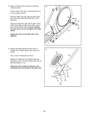
... right Crank Arm (20) while setting the Roller (51) on the other Pedal (not shown) to the Right Pedal Arm (58) with an M8 x 19mm Patch Screw (82), an Axle Cover (53), and an M8 x 25mm Washer (98); 12. Attach the Roller Arm (45) with six #10 x 12.7mm Screws (59) and six M6 Split Washers (111). Apply a small amount of the elliptical. 12...
... right Crank Arm (20) while setting the Roller (51) on the other Pedal (not shown) to the Right Pedal Arm (58) with an M8 x 19mm Patch Screw (82), an Axle Cover (53), and an M8 x 25mm Washer (98); 12. Attach the Roller Arm (45) with six #10 x 12.7mm Screws (59) and six M6 Split Washers (111). Apply a small amount of the elliptical. 12...
English Manual
Page 12
... Axle Cover, do not overtighten the Patch Screw. Attach the Left Pedal Arm (44) to the Right Pedal Arm (58) with the holes in the same way. See step 4. Note: After assembly is completed, some extra parts may 3 be left Roller Arm (45) in the Ramp (3). Attach the Right Pedal Arm (58) to protect the floor. 12 Place a mat beneath the elliptical to the Right Upper Body Leg...
... Axle Cover, do not overtighten the Patch Screw. Attach the Left Pedal Arm (44) to the Right Pedal Arm (58) with the holes in the same way. See step 4. Note: After assembly is completed, some extra parts may 3 be left Roller Arm (45) in the Ramp (3). Attach the Right Pedal Arm (58) to protect the floor. 12 Place a mat beneath the elliptical to the Right Upper Body Leg...
English Manual
Page 13
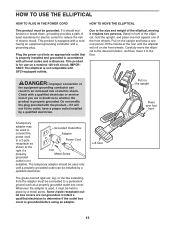
... the outlet box cover is not compatible with GFCI-equipped outlets. HOW TO USE THE ELLIPTICAL HOW TO PLUG IN THE POWER CORD HOW TO MOVE THE ELLIPTICAL This product must be used to Grounded Outlet Box connect the Adapter power cord to a 2-pole Power Cord receptacle as shown at the rear until a properly grounded outlet can result in front of the elliptical, hold the upright, and place...
... the outlet box cover is not compatible with GFCI-equipped outlets. HOW TO USE THE ELLIPTICAL HOW TO PLUG IN THE POWER CORD HOW TO MOVE THE ELLIPTICAL This product must be used to Grounded Outlet Box connect the Adapter power cord to a 2-pole Power Cord receptacle as shown at the rear until a properly grounded outlet can result in front of the elliptical, hold the upright, and place...
English Manual
Page 15
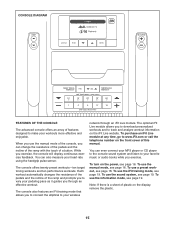
... features an iFit training mode that allows you to connect the elliptical to your pedaling pace as it guides you exercise. CONSOLE DIAGRAM FEATURES OF THE CONSOLE The advanced console offers an array of features designed to make your heart rate using the handgrip pulse sensor. You can also measure your workouts more effective and enjoyable. While you to download personalized workouts and to track and analyze workout information on the display, remove the plastic...
... features an iFit training mode that allows you to connect the elliptical to your pedaling pace as it guides you exercise. CONSOLE DIAGRAM FEATURES OF THE CONSOLE The advanced console offers an array of features designed to make your heart rate using the handgrip pulse sensor. You can also measure your workouts more effective and enjoyable. While you to download personalized workouts and to track and analyze workout information on the display, remove the plastic...
English Manual
Page 16
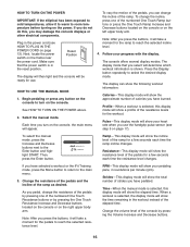
... the power cord (see step 5 on the right upper body arm. Press the Display button repeatedly to the Enter button and highlight START. Resistance-This display mode will show the total number of the pedals by pressing the Volume Increase and Decrease buttons. 16 RPM-This display mode will take a moment for use the handgrip pulse sensor (see HOW TO PLUG IN THE POWER CORD on the power. The console offers several display modes. To change the resistance of strides you press the buttons...
... the power cord (see step 5 on the right upper body arm. Press the Display button repeatedly to the Enter button and highlight START. Resistance-This display mode will show the total number of the pedals by pressing the Volume Increase and Decrease buttons. 16 RPM-This display mode will take a moment for use the handgrip pulse sensor (see HOW TO PLUG IN THE POWER CORD on the power. The console offers several display modes. To change the resistance of strides you press the buttons...
English Manual
Page 17
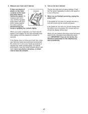
.... When your pulse is detected, your heart rate will be reset. Be careful not to the off position and unplug the power cord. never use alcohol, abrasives, or chemicals to turn off the fan. 7. If the display does not show your heart rate, make sure that your hands or gripping the contacts tightly. When you are finished exercising, press the power switch to move for several...
.... When your pulse is detected, your heart rate will be reset. Be careful not to the off position and unplug the power cord. never use alcohol, abrasives, or chemicals to turn off the fan. 7. If the display does not show your heart rate, make sure that your hands or gripping the contacts tightly. When you are finished exercising, press the power switch to move for several...
English Manual
Page 18
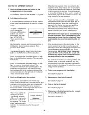
... step 6 on page 16. 3. HOW TO USE A PRESET WORKOUT 1. Then, press the Enter button. You can manually override the setting by pressing the One Touch Resistance buttons and the One Touch Ramp buttons. One resistance level, one ramp incline, and one -minute segments. The workout profile will turn on the console. The flashing segment Current Segment of the profile represents the current segment of the display. See step...
... step 6 on page 16. 3. HOW TO USE A PRESET WORKOUT 1. Then, press the Enter button. You can manually override the setting by pressing the One Touch Resistance buttons and the One Touch Ramp buttons. One resistance level, one ramp incline, and one -minute segments. The workout profile will turn on the console. The flashing segment Current Segment of the profile represents the current segment of the display. See step...
English Manual
Page 19
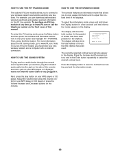
... CD player; For more information about the iFit training mode, go to your MP3 player or CD player. The display will also show the total number (in thousands) of strides that the audio cable is fully plugged in. Press the Display button to www.iFit.com. Note: To use an iFit Live module, you must have been pedaled on the elliptical. HOW TO USE THE SOUND SYSTEM To play...
... CD player; For more information about the iFit training mode, go to your MP3 player or CD player. The display will also show the total number (in thousands) of strides that the audio cable is fully plugged in. Press the Display button to www.iFit.com. Note: To use an iFit Live module, you must have been pedaled on the elliptical. HOW TO USE THE SOUND SYSTEM To play...
English Manual
Page 20
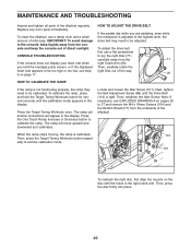
... ramp stops moving, the ramp is adjusted to the highest level, the drive belt may need to be adjusted. To clean the elliptical, use a flat screwdriver to calibrate the ramp. CONSOLE TROUBLESHOOTING If the console does not display your heart rate when you are pedaling, even while the resistance is calibrated. Next, tighten the Belt Adjustment Screw (88) until the calibration mode appears in the right crank arm. Then, retighten the Idler Screw. MAINTENANCE AND TROUBLESHOOTING Inspect and tighten all parts of...
... ramp stops moving, the ramp is adjusted to the highest level, the drive belt may need to be adjusted. To clean the elliptical, use a flat screwdriver to calibrate the ramp. CONSOLE TROUBLESHOOTING If the console does not display your heart rate when you are pedaling, even while the resistance is calibrated. Next, tighten the Belt Adjustment Screw (88) until the calibration mode appears in the right crank arm. Then, retighten the Idler Screw. MAINTENANCE AND TROUBLESHOOTING Inspect and tighten all parts of...

English Manual
Page 21
... the Screw. Turn the Pulley for a moment. Repeat until a Magnet (43) is aligned with the holes in the right crank arm. Slide the Reed Switch slightly closer to pry the left Disc (71) carefully away 71 from the Magnet. To adjust the reed switch, first use a flat screwdriver to or away from the left Crank Arm (20). Rotate the Pulley (19) until the console displays correct...
... the Screw. Turn the Pulley for a moment. Repeat until a Magnet (43) is aligned with the holes in the right crank arm. Slide the Reed Switch slightly closer to pry the left Disc (71) carefully away 71 from the Magnet. To adjust the reed switch, first use a flat screwdriver to or away from the left Crank Arm (20). Rotate the Pulley (19) until the console displays correct...
English Manual
Page 22
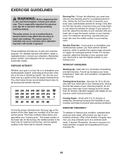
... middle number in general. Remember, the key to achieving results. EXERCISE INTENSITY Whether your breath. For maximum fat burning, exercise with pre-existing health problems. The pulse sensor is intended only as a guide to use your heart rate as an exercise aid in determining heart rate trends in your training zone. (During the first few months of rest between workouts. EXERCISE GUIDELINES WARNING: Before beginning this or any exercise program...
... middle number in general. Remember, the key to achieving results. EXERCISE INTENSITY Whether your breath. For maximum fat burning, exercise with pre-existing health problems. The pulse sensor is intended only as a guide to use your heart rate as an exercise aid in determining heart rate trends in your training zone. (During the first few months of rest between workouts. EXERCISE GUIDELINES WARNING: Before beginning this or any exercise program...

English Manual
Page 23
... Ramp Upright Control Box Front Stabilizer Console Control Box Lid Resistance Bracket Ramp Cover Lift Bracket Lift Roller Lift Motor Transformer Control Board Power Switch Power Cord Grommet Crank Pulley Crank Arm Wiring Grommet Idler C-magnet Motor Bracket Resistance Motor Resistance Arm Resistance Disc Flywheel Flywheel Axle Lift Bushing Lift Axle Stabilizer Cover Foot Wheel Pivot Axle M10 x 25mm Washer Water Bottle Holder Reed Switch Clamp R12 Bearing Right Control Grip/Wire Large Snap Ring Magnet Left Pedal Arm Roller Arm Left Upper Body Leg...
... Ramp Upright Control Box Front Stabilizer Console Control Box Lid Resistance Bracket Ramp Cover Lift Bracket Lift Roller Lift Motor Transformer Control Board Power Switch Power Cord Grommet Crank Pulley Crank Arm Wiring Grommet Idler C-magnet Motor Bracket Resistance Motor Resistance Arm Resistance Disc Flywheel Flywheel Axle Lift Bushing Lift Axle Stabilizer Cover Foot Wheel Pivot Axle M10 x 25mm Washer Water Bottle Holder Reed Switch Clamp R12 Bearing Right Control Grip/Wire Large Snap Ring Magnet Left Pedal Arm Roller Arm Left Upper Body Leg...
English Manual
Page 24
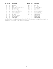
Qty. Drive Belt Audio Cable #6 x 9.5mm Screw Upper Bushing Mount Motor Bracket Screw Small Snap Ring Lower Wire Harness Adjustment Nut Assembly Tool Grease Packet Userʼs Manual Note: Specifications are not illustrated. 24 Description 101 1 102 8 103 1 104 35 105 12 106 2 107 4 108 2 109 3 110 1 111 12 112 1 Idler Screw M8 Locknut M3.5 x 12mm Flat Head Screw M4 x 16mm Screw M4 x 12mm Flange Screw M4 x 16mm Bright Screw Roller Arm Bushing...
Qty. Drive Belt Audio Cable #6 x 9.5mm Screw Upper Bushing Mount Motor Bracket Screw Small Snap Ring Lower Wire Harness Adjustment Nut Assembly Tool Grease Packet Userʼs Manual Note: Specifications are not illustrated. 24 Description 101 1 102 8 103 1 104 35 105 12 106 2 107 4 108 2 109 3 110 1 111 12 112 1 Idler Screw M8 Locknut M3.5 x 12mm Flat Head Screw M4 x 16mm Screw M4 x 12mm Flange Screw M4 x 16mm Bright Screw Roller Arm Bushing...
English Manual
Page 28
... the product (see the front cover of this manual) • the key number and description of the replacement part(s) (see the front cover of this manual. ICON Health & Fitness, Inc. (ICON) warrants this product to be free from state to www.healthriderservice.com/registration. All repairs for which warranty claims are warranted for a particular purpose are limited in connection with respect to you specific legal rights. or other...
... the product (see the front cover of this manual) • the key number and description of the replacement part(s) (see the front cover of this manual. ICON Health & Fitness, Inc. (ICON) warrants this product to be free from state to www.healthriderservice.com/registration. All repairs for which warranty claims are warranted for a particular purpose are limited in connection with respect to you specific legal rights. or other...


