
Product Manual
Page 4
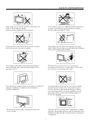
... can also be built into the television cabinet slots or openings. Serious injury may result if it is not used in the operation of the TV. To prevent fire or electrical shock hazard, do not expose the television receiver to direct sunlight and other products which give off heat, e.g. Avoid exposing...
... can also be built into the television cabinet slots or openings. Serious injury may result if it is not used in the operation of the TV. To prevent fire or electrical shock hazard, do not expose the television receiver to direct sunlight and other products which give off heat, e.g. Avoid exposing...
Product Manual
Page 5
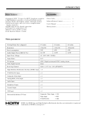
...THD 7%): Input Power Voltage: 1366x768 30W 1366x768 60W 2x1.5W 2x3W AC 100V-240V 50/60Hz 1920x1080 60W 2x3W Aspect Ratio: 16:9 TV System: Video Signal System: Receiving Channel: ATSC Digital system and NTSC Analog system NTSC Cable :1-135/ Air: 2-69 (ATV&DTV)...) Input x 1 Composite Video Input x 1 Analog RGB (VGA) Input x 1 Audio Input x 2 Headphone Output x 1 Coaxial Output x 1 USB Input Horizontal definition (TV line) x 1 Composite Video Input >=350 Video Input >=400 YCb(Pb)Cr(Pr) >=400 HDMI, the HDMI logo and High-Definition Multimedia Interface are trademarks or...
...THD 7%): Input Power Voltage: 1366x768 30W 1366x768 60W 2x1.5W 2x3W AC 100V-240V 50/60Hz 1920x1080 60W 2x3W Aspect Ratio: 16:9 TV System: Video Signal System: Receiving Channel: ATSC Digital system and NTSC Analog system NTSC Cable :1-135/ Air: 2-69 (ATV&DTV)...) Input x 1 Composite Video Input x 1 Analog RGB (VGA) Input x 1 Audio Input x 2 Headphone Output x 1 Coaxial Output x 1 USB Input Horizontal definition (TV line) x 1 Composite Video Input >=350 Video Input >=400 YCb(Pb)Cr(Pr) >=400 HDMI, the HDMI logo and High-Definition Multimedia Interface are trademarks or...
Product Manual
Page 6
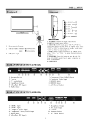
... AC Power Socket REAR AV INPUT/OUTPUT (L22B1120) HDMI 1 HDMI 2 1 2 1. HDMI2 Input 3. AC Power Socket -5- CH+/CH-: In TV mode, press "CH+" or "CH-" to STANDBY. 6. Press it again to turn the set back to change the channel up and down. HDMI2...CH- 3 VOL+ 1 4 VOL- 2 STANDBY 5 USB 6 30 30 1: Remote control sensor. 1 2 3 4 5 6 7 8 9 0 2: Indicator LED: GREEN POWER ON. " to turn on the TV. 4. VGA Port (PC Input) 6. Audio Input R Y AV HDMI 2 HDMI 1 COMPONENT INPUT L Pb Pr 6 7 89 10 11 7. RED STANDBY. + + VOL CH _ _ 3: Side panel keys 1....
... AC Power Socket REAR AV INPUT/OUTPUT (L22B1120) HDMI 1 HDMI 2 1 2 1. HDMI2 Input 3. AC Power Socket -5- CH+/CH-: In TV mode, press "CH+" or "CH-" to STANDBY. 6. Press it again to turn the set back to change the channel up and down. HDMI2...CH- 3 VOL+ 1 4 VOL- 2 STANDBY 5 USB 6 30 30 1: Remote control sensor. 1 2 3 4 5 6 7 8 9 0 2: Indicator LED: GREEN POWER ON. " to turn on the TV. 4. VGA Port (PC Input) 6. Audio Input R Y AV HDMI 2 HDMI 1 COMPONENT INPUT L Pb Pr 6 7 89 10 11 7. RED STANDBY. + + VOL CH _ _ 3: Side panel keys 1....
Product Manual
Page 7
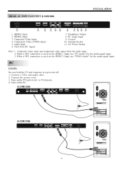
... 10 7. When a DVI connection is used on the HDMI 2 Input, use "PC Audio" for the audio signal input. INSTALLATION REAR AV INPUT/OUTPUT (L24B1180) AC INPUT 100-240V~50/60Hz HDMI 1 HDMI 2 11 1 2 1. HDMI2 Input 3. Antenna Socket 11. Turn on the PC. (L19B1120) RF ...INPUT HEADPHONE PC AUDIO INPUT COAXIAL RF INPUT AC INPUT 100-240V~50/60Hz -6- Coaxial 10. Connect a VGA and audio cable. 2. Turn on the TV and switch to VGAmode. 4. PC Audio Input 9. AC Power Socket Note: 1. Headphone Output 8. Connect the power cord. 3. HDMI1 Input 2. Component...
... 10 7. When a DVI connection is used on the HDMI 2 Input, use "PC Audio" for the audio signal input. INSTALLATION REAR AV INPUT/OUTPUT (L24B1180) AC INPUT 100-240V~50/60Hz HDMI 1 HDMI 2 11 1 2 1. HDMI2 Input 3. Antenna Socket 11. Turn on the PC. (L19B1120) RF ...INPUT HEADPHONE PC AUDIO INPUT COAXIAL RF INPUT AC INPUT 100-240V~50/60Hz -6- Coaxial 10. Connect a VGA and audio cable. 2. Turn on the TV and switch to VGAmode. 4. PC Audio Input 9. AC Power Socket Note: 1. Headphone Output 8. Connect the power cord. 3. HDMI1 Input 2. Component...
Product Manual
Page 10
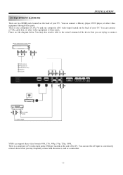
There is a composite (AV) video input and a USB port located on the back of your TV. VIDEO EQUIPMENT with YPbPr GBR WR Y Yellow (video) W White(audio L) R Red(audio R or Pr) B Blue(Pb) G Green(Y) RF INPUT COAXIAL PC AUDIO INPUT HEADPHONE VGA ... EQUIPMENT W R TO VIDEO output To audio outputs There is one component (Y, Pb, Pr) and one composite (AV) video input located on the side of the TV. INSTALLATION AV EQUIPMENT (L19B1120) There are trying to these ports. You may frequently connect and disconnect, such as a camcorder. -9- Please see the diagram below. You...
There is a composite (AV) video input and a USB port located on the back of your TV. VIDEO EQUIPMENT with YPbPr GBR WR Y Yellow (video) W White(audio L) R Red(audio R or Pr) B Blue(Pb) G Green(Y) RF INPUT COAXIAL PC AUDIO INPUT HEADPHONE VGA ... EQUIPMENT W R TO VIDEO output To audio outputs There is one component (Y, Pb, Pr) and one composite (AV) video input located on the side of the TV. INSTALLATION AV EQUIPMENT (L19B1120) There are trying to these ports. You may frequently connect and disconnect, such as a camcorder. -9- Please see the diagram below. You...
Product Manual
Page 11
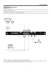
... the owner's manual of the device that you are two HDMI ports located on the back of your TV. There is a composite (AV) video input and a USB port located on the back of your TV. Please see the diagram below. You can connect a Blu-ray player, DVD player, or other video ... EQUIPMENT W R TO VIDEO output To audio outputs There is one component (Y, Pb, Pr) and one composite (AV) video input located on the side of the TV. You can connect a VCR, cable box, or other video equipment through these jacks. INSTALLATION AV EQUIPMENT (L22B1120) There are trying to these ports.
... the owner's manual of the device that you are two HDMI ports located on the back of your TV. There is a composite (AV) video input and a USB port located on the back of your TV. Please see the diagram below. You can connect a Blu-ray player, DVD player, or other video ... EQUIPMENT W R TO VIDEO output To audio outputs There is one component (Y, Pb, Pr) and one composite (AV) video input located on the side of the TV. You can connect a VCR, cable box, or other video equipment through these jacks. INSTALLATION AV EQUIPMENT (L22B1120) There are trying to these ports.
Product Manual
Page 12
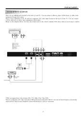
INSTALLATION AV EQUIPMENT (L24B1180) There are trying to connect. You can connect a Blu-ray player, DVD player, or other video equipment to the owner's manual of your TV. Please see the diagram below. VIDEO EQUIPMENT with YPbPr GBR WR Y Yellow (video) W White(audio L) R Red(audio R or Pr) B Blue(Pb) G ...TO VIDEO output To audio outputs There is one component (Y, Pb, Pr) and one composite (AV) video input located on the side of your TV. You can use this AV input to conveniently connect devices that you may also need to refer to these ports. You can connect a VCR, ...
INSTALLATION AV EQUIPMENT (L24B1180) There are trying to connect. You can connect a Blu-ray player, DVD player, or other video equipment to the owner's manual of your TV. Please see the diagram below. VIDEO EQUIPMENT with YPbPr GBR WR Y Yellow (video) W White(audio L) R Red(audio R or Pr) B Blue(Pb) G ...TO VIDEO output To audio outputs There is one component (Y, Pb, Pr) and one composite (AV) video input located on the side of your TV. You can use this AV input to conveniently connect devices that you may also need to refer to these ports. You can connect a VCR, ...
Product Manual
Page 13
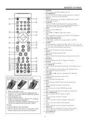
... matches the polarity marks inside the unit. 3. POWER MUTE 1 11 RECALL 123 12 2 456 7890 MENU 3 SOURCE 13 14 4 ENTER 5 15 EXIT TV DISPLAY 16 + S.M + 6 VOL 17 CH _ _ P.M 7 PAGE UP PAGE DOWN 8 SLEEP EPG P.G ASPECT 9 18 10 CH LIST EPG FAV 19 21...switch betweenthe current and previouslyviewed channel. 13: SOURCE Press to display orexit the TVinput source menu. 14: ENTER Press to confirm aselection. 15: TV DISPLAY Press to show the following symptoms: Operation is not to switch audio modes: Standard, News, Music,Theater, Sports orCustom. 17: CH+/...
... matches the polarity marks inside the unit. 3. POWER MUTE 1 11 RECALL 123 12 2 456 7890 MENU 3 SOURCE 13 14 4 ENTER 5 15 EXIT TV DISPLAY 16 + S.M + 6 VOL 17 CH _ _ P.M 7 PAGE UP PAGE DOWN 8 SLEEP EPG P.G ASPECT 9 18 10 CH LIST EPG FAV 19 21...switch betweenthe current and previouslyviewed channel. 13: SOURCE Press to display orexit the TVinput source menu. 14: ENTER Press to confirm aselection. 15: TV DISPLAY Press to show the following symptoms: Operation is not to switch audio modes: Standard, News, Music,Theater, Sports orCustom. 17: CH+/...
Product Manual
Page 15
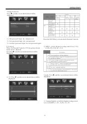
... encoded in the dataof older movies. Restrict. Press the ENTER key to Suggested order children) X age TV-G(General audience) TV-PG(Parental Guidance suggested . Under 17 requires accompanyingparent or adult R guardian (age varies insome jurisdictions). US... Exit Rating Content Content FV V S L D (Fantasy (Violence) (Sexual (Adult (Sexually violence) situation) language) suggestive dialog) TV-Y (All children) TV-Y7(Direct to lock/unlock Parental Controls. 2). Old password New password Confirm password ---------- MPAA: switch the movie-rating control level: ...
... encoded in the dataof older movies. Restrict. Press the ENTER key to Suggested order children) X age TV-G(General audience) TV-PG(Parental Guidance suggested . Under 17 requires accompanyingparent or adult R guardian (age varies insome jurisdictions). US... Exit Rating Content Content FV V S L D (Fantasy (Violence) (Sexual (Adult (Sexually violence) situation) language) suggestive dialog) TV-Y (All children) TV-Y7(Direct to lock/unlock Parental Controls. 2). Old password New password Confirm password ---------- MPAA: switch the movie-rating control level: ...
Product Manual
Page 16
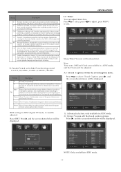
... BG color FG opacity BG opacity Adjust Select Custom > Default > Default > Default > Default Default > Default > Default > Default > Menu Exit NOTE: Only available in ATSC digital TV mode, it mustbe integral to select Closed Caption, press , and the screen shown below will be displayed.
... BG color FG opacity BG opacity Adjust Select Custom > Default > Default > Default > Default Default > Default > Default > Default > Menu Exit NOTE: Only available in ATSC digital TV mode, it mustbe integral to select Closed Caption, press , and the screen shown below will be displayed.
Product Manual
Page 17
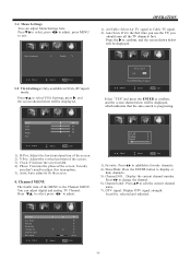
...button to edit the current channel name. 7). Channel label: Press to display or hide channels. 5). Air/Cable: Select Air TV signal or Cable TV signal. 2). H-Pos: Adjust the horizontal position of the screen. 3). Press to select, press to change the channel. 6). ...the MENU is progressing. Usually you don't need to exit. You can adjust Menu Settings here. 3.4 Menu Settings You can adjust digital and analog TV Channel. Menu Language < English > Adjust Select Menu Exit 3.5 VGASettings: Only available inVGA (PCinput) mode. OPERATION 1). R F CH: 4 Found:...
...button to edit the current channel name. 7). Channel label: Press to display or hide channels. 5). Air/Cable: Select Air TV signal or Cable TV signal. 2). H-Pos: Adjust the horizontal position of the screen. 3). Press to select, press to change the channel. 6). ...the MENU is progressing. Usually you don't need to exit. You can adjust Menu Settings here. 3.4 Menu Settings You can adjust digital and analog TV Channel. Menu Language < English > Adjust Select Menu Exit 3.5 VGASettings: Only available inVGA (PCinput) mode. OPERATION 1). R F CH: 4 Found:...
Product Manual
Page 19
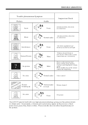
... on the remote control for inspecting Normal audio Color control Picture breaking up Normal audio Retune channel or weak No color Noise TVsystem The LCD TV panel is not opened Contrast and brightness/volume setup Press standby key on the screen as a fixed point of the product. -18-
... on the remote control for inspecting Normal audio Color control Picture breaking up Normal audio Retune channel or weak No color Noise TVsystem The LCD TV panel is not opened Contrast and brightness/volume setup Press standby key on the screen as a fixed point of the product. -18-


