User Manual
Page 2
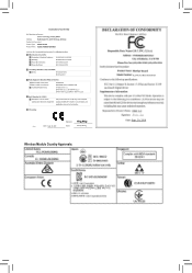
Motherboard X299X AORUS MASTER Sept. 20, 2019 Wireless Module Country Approvals: Motherboard X299X AORUS MASTER Sept. 20, 2019
Motherboard X299X AORUS MASTER Sept. 20, 2019 Wireless Module Country Approvals: Motherboard X299X AORUS MASTER Sept. 20, 2019
User Manual
Page 3
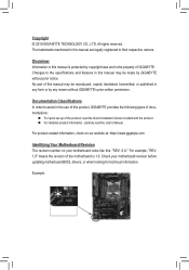
...without prior notice. For product-related information, check on our website at: https://www.gigabyte.com Identifying Your Motherboard Revision The revision number on your motherboard revision before updating motherboard BIOS, drivers, or when looking for technical information. Changes to their respective owners...., copied, translated, transmitted, or published in this product, GIGABYTE provides the following types of documentations: „„ For quick set-up of GIGABYTE. All rights reserved. No part of the motherboard is the property of the product, read the Quick Installation ...
...without prior notice. For product-related information, check on our website at: https://www.gigabyte.com Identifying Your Motherboard Revision The revision number on your motherboard revision before updating motherboard BIOS, drivers, or when looking for technical information. Changes to their respective owners...., copied, translated, transmitted, or published in this product, GIGABYTE provides the following types of documentations: „„ For quick set-up of GIGABYTE. All rights reserved. No part of the motherboard is the property of the product, read the Quick Installation ...
User Manual
Page 4
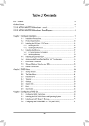
Table of Contents Box Contents...6 Optional Items...6 X299X AORUS MASTER Motherboard Layout 7 X299X AORUS MASTER Motherboard Block Diagram 8 Chapter 1 Hardware Installation 9 1-1 Installation Precautions 9 1-2 Product Specifications 10 1-3 Installing the CPU and CPU Cooler 14 1-3-1 Installing the CPU 14 1-3-2 Installing the CPU Cooler ...
Table of Contents Box Contents...6 Optional Items...6 X299X AORUS MASTER Motherboard Layout 7 X299X AORUS MASTER Motherboard Block Diagram 8 Chapter 1 Hardware Installation 9 1-1 Installation Precautions 9 1-2 Product Specifications 10 1-3 Installing the CPU and CPU Cooler 14 1-3-1 Installing the CPU 14 1-3-2 Installing the CPU Cooler ...
User Manual
Page 6
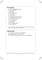
.... 12CR1-FPX582-2*R) - 6 - The box contents are for reference only and the actual items shall depend on the product package you obtain. Box Contents 55 X299X AORUS MASTER motherboard 55 Motherboard driver disc 55 User's Manual 55 Quick Installation Guide 55 Four SATA cables 55 One Wi-Fi antenna 55 One addressable LED strip adapter cable...
.... 12CR1-FPX582-2*R) - 6 - The box contents are for reference only and the actual items shall depend on the product package you obtain. Box Contents 55 X299X AORUS MASTER motherboard 55 Motherboard driver disc 55 User's Manual 55 Quick Installation Guide 55 Four SATA cables 55 One Wi-Fi antenna 55 One addressable LED strip adapter cable...

User Manual
Page 7
DDR4_4_2C DDR4_2_1C DDR4_3_2D DDR4_1_1D ATX_12V_2X4_2 ATX_12V_2X4_1 EC_TEMP2 EC_TEMP1 ATX LED_C2 D_LED2 SYS_FAN5_PUMP SYS_FAN6_PUMP F_U32_2 F_U32C X299X AORUS MASTER Motherboard Layout DDR4_1_1B DDR4_3_2B DDR4_2_1A DDR4_4_2A REAR_BUTTON U32_20 U32G2 U32G2C Realtek® USB 3.2 Gen 1 Hub ASMedia®...U32_LAN2 LGA2066 SYS_FAN1 U32_LAN1 Intel® GbE LAN (Note 1) M2_WIFI AUDIO Aquantia 5GbE LAN (Note 1) PCIEX16_1 110 80 60 X299X CPU_FAN AORUS MASTER CPU_OPT BAT M2M CPU DRAM VGA BOOT ASMedia® USB 3.2 Gen 2 Controller SATA3 7531 6420 PCIEX8_1 ESS SABRE9218 110 80...
DDR4_4_2C DDR4_2_1C DDR4_3_2D DDR4_1_1D ATX_12V_2X4_2 ATX_12V_2X4_1 EC_TEMP2 EC_TEMP1 ATX LED_C2 D_LED2 SYS_FAN5_PUMP SYS_FAN6_PUMP F_U32_2 F_U32C X299X AORUS MASTER Motherboard Layout DDR4_1_1B DDR4_3_2B DDR4_2_1A DDR4_4_2A REAR_BUTTON U32_20 U32G2 U32G2C Realtek® USB 3.2 Gen 1 Hub ASMedia®...U32_LAN2 LGA2066 SYS_FAN1 U32_LAN1 Intel® GbE LAN (Note 1) M2_WIFI AUDIO Aquantia 5GbE LAN (Note 1) PCIEX16_1 110 80 60 X299X CPU_FAN AORUS MASTER CPU_OPT BAT M2M CPU DRAM VGA BOOT ASMedia® USB 3.2 Gen 2 Controller SATA3 7531 6420 PCIEX8_1 ESS SABRE9218 110 80...
User Manual
Page 8
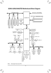
PCI Express x16_1 PCI Express x16_2 PCI Express x8_1 PCI Express x8_2 DMI 3.0 X299X AORUS MASTER Motherboard Block Diagram PCI Express 3.0 Bus x16 x16 x8 Switch CPU CLK+/- (100~500 MHz) LGA2066 CPU DDR4 2933 (Note)/2666/2400/2133 MHz 1 M.2 Socket 3 (M2M) 1 M.2 ...
PCI Express x16_1 PCI Express x16_2 PCI Express x8_1 PCI Express x8_2 DMI 3.0 X299X AORUS MASTER Motherboard Block Diagram PCI Express 3.0 Bus x16 x16 x8 Switch CPU CLK+/- (100~500 MHz) LGA2066 CPU DDR4 2933 (Note)/2666/2400/2133 MHz 1 M.2 Socket 3 (M2M) 1 M.2 ...

User Manual
Page 9
... the installation process can become damaged as a result of electrostatic discharge (ESD). Chapter 1 Hardware Installation 1-1 Installation Precautions The motherboard contains numerous delicate electronic circuits and components which can lead to damage to system components as well as physical harm to the user...make sure the chassis is best to wear an electrostatic discharge (ESD) wrist strap when handling electronic com- ponents such as a motherboard, CPU or memory. Prior to installation, carefully read the user's manual and follow these procedures: •• Prior to ...
... the installation process can become damaged as a result of electrostatic discharge (ESD). Chapter 1 Hardware Installation 1-1 Installation Precautions The motherboard contains numerous delicate electronic circuits and components which can lead to damage to system components as well as physical harm to the user...make sure the chassis is best to wear an electrostatic discharge (ESD) wrist strap when handling electronic com- ponents such as a motherboard, CPU or memory. Prior to installation, carefully read the user's manual and follow these procedures: •• Prior to ...

User Manual
Page 13
... the right to make any changes to download the latest version of apps. Please visit GIGABYTE's website for support lists of each application may vary by motherboard model. Unique Features ŠŠ ŠŠ ŠŠ ŠŠ Bundled ŠŠ Software ŠŠ ŠŠ Operating System ŠŠ Support for...
... the right to make any changes to download the latest version of apps. Please visit GIGABYTE's website for support lists of each application may vary by motherboard model. Unique Features ŠŠ ŠŠ ŠŠ ŠŠ Bundled ŠŠ Software ŠŠ ŠŠ Operating System ŠŠ Support for...
User Manual
Page 14
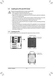
...your hardware specifications including the CPU, graphics card, memory, hard drive, etc. 1-3-1 Installing the CPU A. Locate the alignment keys on the motherboard CPU socket and the notches on the CPU Notch Notch - 14 - The CPU cannot be set the frequency beyond hardware specifications since it ...Apply an even and thin layer of thermal grease on the computer if the CPU cooler is not recommended that the motherboard supports the CPU. (Go to GIGABYTE's website for the peripherals. LGA2066 CPU Socket Alignment Key Alignment Key Pin One Corner of the CPU Socket Hardware Installation ...
...your hardware specifications including the CPU, graphics card, memory, hard drive, etc. 1-3-1 Installing the CPU A. Locate the alignment keys on the motherboard CPU socket and the notches on the CPU Notch Notch - 14 - The CPU cannot be set the frequency beyond hardware specifications since it ...Apply an even and thin layer of thermal grease on the computer if the CPU cooler is not recommended that the motherboard supports the CPU. (Go to GIGABYTE's website for the peripherals. LGA2066 CPU Socket Alignment Key Alignment Key Pin One Corner of the CPU Socket Hardware Installation ...

User Manual
Page 15
... the CPU into the socket vertically. Step 4: Hold the CPU with the triangle mark on metal socket frame and carefully insert the CPU into the motherboard CPU socket. •• Before installing the CPU, make sure to turn off the computer and unplug the power cord from the socket. Lever A Lever...
... the CPU into the socket vertically. Step 4: Hold the CPU with the triangle mark on metal socket frame and carefully insert the CPU into the motherboard CPU socket. •• Before installing the CPU, make sure to turn off the computer and unplug the power cord from the socket. Lever A Lever...
User Manual
Page 16
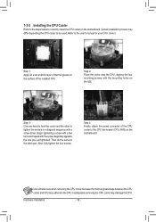
... Use one you just tightened. Then do the same to the other to tighten the screws in a diagonal sequence with the mounting holes on the motherboard. Step 4: Finally, attach the power connector of the installed CPU. 1-3-2 Installing the CPU Cooler Refer to the steps below to correctly install the ...CPU cooler on the motherboard. (Actual installation process may adhere to the CPU. Refer to the user's manual for your CPU cooler.) Step 1: Apply an even and thin ...
... Use one you just tightened. Then do the same to the other to tighten the screws in a diagonal sequence with the mounting holes on the motherboard. Step 4: Finally, attach the power connector of the installed CPU. 1-3-2 Installing the CPU Cooler Refer to the steps below to correctly install the ...CPU cooler on the motherboard. (Actual installation process may adhere to the CPU. Refer to the user's manual for your CPU cooler.) Step 1: Apply an even and thin ...
User Manual
Page 17
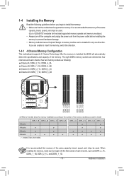
... direction. When installing the memory, make sure to begin to install the memory: •• Make sure that the motherboard supports the memory. It is installed, the BIOS will automatically detect the specifications and capacity of each channel has two memory...sockets are unable to insert the memory, switch the direction. 1-4-1 4 Channel Memory Configuration This motherboard supports 4 Channel Technology. Hardware Installation A memory module can be used . (Go to GIGABYTE's website for memory installation according to the number of the memory modules you begin with the ...
... direction. When installing the memory, make sure to begin to install the memory: •• Make sure that the motherboard supports the memory. It is installed, the BIOS will automatically detect the specifications and capacity of each channel has two memory...sockets are unable to insert the memory, switch the direction. 1-4-1 4 Channel Memory Configuration This motherboard supports 4 Channel Technology. Hardware Installation A memory module can be used . (Go to GIGABYTE's website for memory installation according to the number of the memory modules you begin with the ...

User Manual
Page 18
... insert it can only fit in one direction. Follow the steps below to the memory module. Hardware Installation - 18 - Place the memory module on this motherboard. As indicated in the memory sockets. Step 2: The clip at the right end of the memory module. Step 1: Note the orientation of the memory socket...
... insert it can only fit in one direction. Follow the steps below to the memory module. Hardware Installation - 18 - Place the memory module on this motherboard. As indicated in the memory sockets. Step 2: The clip at the right end of the memory module. Step 1: Note the orientation of the memory socket...
User Manual
Page 19
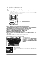
... off the computer and unplug the power cord from the power outlet before you begin to install an expansion card: •• Make sure the motherboard supports the expansion card. If necessary, go to BIOS Setup to make any required BIOS changes for your operating system. Install the driver provided with...
... off the computer and unplug the power cord from the power outlet before you begin to install an expansion card: •• Make sure the motherboard supports the expansion card. If necessary, go to BIOS Setup to make any required BIOS changes for your operating system. Install the driver provided with...
User Manual
Page 20
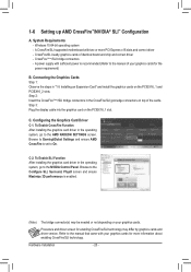
... operating system -- C. Configuring the Graphics Card Driver C-1. 1-6 Setting up AMD CrossFire™/NVIDIA® SLI™ Configuration A. Hardware Installation - 20 - System Requirements -- A CrossFire/SLI-supported motherboard with your graphics cards.
... operating system -- C. Configuring the Graphics Card Driver C-1. 1-6 Setting up AMD CrossFire™/NVIDIA® SLI™ Configuration A. Hardware Installation - 20 - System Requirements -- A CrossFire/SLI-supported motherboard with your graphics cards.
User Manual
Page 22
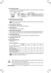
... using this audio jack for line in connector. Line Out/Front Speaker Out The line out jack. Do not rock it straight out from the motherboard. •• When removing the cable, pull it side to side to 5 Gbps data rate.
... using this audio jack for line in connector. Line Out/Front Speaker Out The line out jack. Do not rock it straight out from the motherboard. •• When removing the cable, pull it side to side to 5 Gbps data rate.
User Manual
Page 24
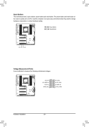
Quick Buttons This motherboard has 2 quick buttons: power button and reset button. PW_SW: Power Button RST_SW: Reset Button RST_SW PW_SW Voltage Measurement Points Use a multimeter to change hardware components or conduct hardware testing. VCCIO CPU_MESH VCCST VDDR_AB VCCSA CPU_VRIN VDDR_CD PCH_CORE ++++ ++++ Hardware Installation - 24 - The power button and reset button allow users to quickly turn on/off or reset the computer in an open-case environment when they want to measure the following motherboard voltages.
Quick Buttons This motherboard has 2 quick buttons: power button and reset button. PW_SW: Power Button RST_SW: Reset Button RST_SW PW_SW Voltage Measurement Points Use a multimeter to change hardware components or conduct hardware testing. VCCIO CPU_MESH VCCST VDDR_AB VCCSA CPU_VRIN VDDR_CD PCH_CORE ++++ ++++ Hardware Installation - 24 - The power button and reset button allow users to quickly turn on/off or reset the computer in an open-case environment when they want to measure the following motherboard voltages.
User Manual
Page 25
... sure your devices are compliant with the connectors you wish to connect. •• Before installing the devices, be sure to the connector on the motherboard. - 25 -
... sure your devices are compliant with the connectors you wish to connect. •• Before installing the devices, be sure to the connector on the motherboard. - 25 -

User Manual
Page 26
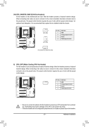
The power connector possesses a foolproof design. If the 12V power connector is turned off and all the components on the motherboard. To meet expansion requirements, it is used (500W or greater). Definition 1 GND (Only for 2x4-pin 12V) 2 GND (Only for 2x4-pin 12V) 3 GND 4 GND 5 +...
The power connector possesses a foolproof design. If the 12V power connector is turned off and all the components on the motherboard. To meet expansion requirements, it is used (500W or greater). Definition 1 GND (Only for 2x4-pin 12V) 2 GND (Only for 2x4-pin 12V) 3 GND 4 GND 5 +...
User Manual
Page 27
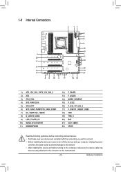
... the system may result in the correct orientation (the black connector wire is the ground wire). Hardware Installation Do not place a jumper cap on this motherboard are not configuration jumper blocks. For optimum heat dissipation, it is recommended that a system fan be sure to connect it in damage to prevent your...
... the system may result in the correct orientation (the black connector wire is the ground wire). Hardware Installation Do not place a jumper cap on this motherboard are not configuration jumper blocks. For optimum heat dissipation, it is recommended that a system fan be sure to connect it in damage to prevent your...


