Manual
Page 3
......4 MSH61DI Motherboard Layout 5 Chapter 1 Hardware Installation 7 1-1 Installation Precautions 7 1-2 Product Specifications 8 1-3 Installing the CPU and CPU Cooler 10 1-3-1 Installing the CPU...10 1-3-2 Installing the CPU Cooler 12 1-4 Installing the Memory 13 1-4-1 Dual Channel Memory Configuration 13 1-4-2 Installing a Memory 14 1-5 Back Panel Connectors 15 1-6 Internal Connectors 17 Chapter 2 BIOS Setup 27 2-1 The Main Menu 29 2-2 Advanced Menu 31 2-2-1 ACPI Settings...32 2-2-2 CPU Configuration 33 2-2-3 SATA Configuration 35 2-2-4 Intel TXT(LT) Configuration 37 2-2-5 USB...
......4 MSH61DI Motherboard Layout 5 Chapter 1 Hardware Installation 7 1-1 Installation Precautions 7 1-2 Product Specifications 8 1-3 Installing the CPU and CPU Cooler 10 1-3-1 Installing the CPU...10 1-3-2 Installing the CPU Cooler 12 1-4 Installing the Memory 13 1-4-1 Dual Channel Memory Configuration 13 1-4-2 Installing a Memory 14 1-5 Back Panel Connectors 15 1-6 Internal Connectors 17 Chapter 2 BIOS Setup 27 2-1 The Main Menu 29 2-2 Advanced Menu 31 2-2-1 ACPI Settings...32 2-2-2 CPU Configuration 33 2-2-3 SATA Configuration 35 2-2-4 Intel TXT(LT) Configuration 37 2-2-5 USB...
Manual
Page 6
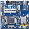
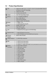
...Description Speaker cable connector Audio Line In port Optical S/PDIF Out connector USB 3.0 ports USB 2.0 ports Battery connector HDMI port Clear CMOS jumper RJ45 LAN port DC In power connector 2 pin power connector Mini PCi Express connector MSATA connector Touch panel USB connector TV tuner USB connector Back Light switch Front panelconnector SATA cable connectors Hard disk power connector USB connector Audio cable connector CPU fan connector Intel LGA1155 socket System fan connector Flat Panel Display connector LVDS connector Digital Mic connector WEBCAM connector DDR3 SO-DIMM slot (channel...
...Description Speaker cable connector Audio Line In port Optical S/PDIF Out connector USB 3.0 ports USB 2.0 ports Battery connector HDMI port Clear CMOS jumper RJ45 LAN port DC In power connector 2 pin power connector Mini PCi Express connector MSATA connector Touch panel USB connector TV tuner USB connector Back Light switch Front panelconnector SATA cable connectors Hard disk power connector USB connector Audio cable connector CPU fan connector Intel LGA1155 socket System fan connector Flat Panel Display connector LVDS connector Digital Mic connector WEBCAM connector DDR3 SO-DIMM slot (channel...
Manual
Page 7
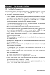
... unplugging the power supply cable from the power outlet before installing or removing the motherboard or other hardware components. • When connecting hardware components to the internal connectors on the motherboard, make sure the power supply voltage has been set according to the local voltage standard. • Before using the product, please verify that all cables and power connectors of your dealer. Prior to installation, carefully read the user's manual and follow these...
... unplugging the power supply cable from the power outlet before installing or removing the motherboard or other hardware components. • When connecting hardware components to the internal connectors on the motherboard, make sure the power supply voltage has been set according to the local voltage standard. • Before using the product, please verify that all cables and power connectors of your dealer. Prior to installation, carefully read the user's manual and follow these...
Manual
Page 8
...;i5, Core™i3 processors/Intel® Pentium® processors in Intel® processor 2 x SATA 3Gb/s connectors USB Internal Connectors ŠŠ 2 x USB 3.0 ports (back panel) ŠŠ 2 x USB 2.0 ports (back panel) ŠŠ 5 x USB 2.0/1.1 header (Card reader/Touch panel/webcam and other devices) ŠŠ 2 x SATA 3Gb/s connectors ŠŠ 1 x HDD power connector ŠŠ 1 x CPU fan header ŠŠ 1 x System fan header ŠŠ 1 x Front panel header ŠŠ 1 x Audio header ŠŠ 3 x USB 2.0 headers ŠŠ 1 x Speaker header Š...
...;i5, Core™i3 processors/Intel® Pentium® processors in Intel® processor 2 x SATA 3Gb/s connectors USB Internal Connectors ŠŠ 2 x USB 3.0 ports (back panel) ŠŠ 2 x USB 2.0 ports (back panel) ŠŠ 5 x USB 2.0/1.1 header (Card reader/Touch panel/webcam and other devices) ŠŠ 2 x SATA 3Gb/s connectors ŠŠ 1 x HDD power connector ŠŠ 1 x CPU fan header ŠŠ 1 x System fan header ŠŠ 1 x Front panel header ŠŠ 1 x Audio header ŠŠ 3 x USB 2.0 headers ŠŠ 1 x Speaker header Š...
Manual
Page 10
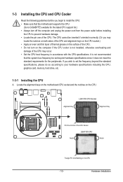
... bus frequency be inserted if oriented incorrectly. (Or you may occur. • Set the CPU host frequency in accordance with the CPU specifications. Locate the alignment keys on the motherboard CPU socket and the notches on the CPU - 10 - Hardware Installation 1-3 Installing the CPU and CPU Cooler Read the following guidelines before installing the CPU to your hardware specifications including the CPU, graphics card, memory, hard drive, etc. 1-3-1 Installing the CPU A. If you wish to set beyond the standard specifications...
... bus frequency be inserted if oriented incorrectly. (Or you may occur. • Set the CPU host frequency in accordance with the CPU specifications. Locate the alignment keys on the motherboard CPU socket and the notches on the CPU - 10 - Hardware Installation 1-3 Installing the CPU and CPU Cooler Read the following guidelines before installing the CPU to your hardware specifications including the CPU, graphics card, memory, hard drive, etc. 1-3-1 Installing the CPU A. If you wish to set beyond the standard specifications...
Manual
Page 13
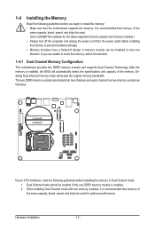
Dual Channel mode cannot be installed in Dual Channel mode. 1. A memory module can be enabled if only one direction. The two DDR3 memory sockets are unable to insert the memory, switch the direction. 1-4-1 Dual Channel Memory Configuration This motherboard provides two DDR3 memory sockets and supports Dual Channel Technology. It is recommended that memory of the same capacity, brand, speed, and chips be used for the latest supported memory speeds and memory modules.) • Always turn off the computer and unplug the power cord from...
Dual Channel mode cannot be installed in Dual Channel mode. 1. A memory module can be enabled if only one direction. The two DDR3 memory sockets are unable to insert the memory, switch the direction. 1-4-1 Dual Channel Memory Configuration This motherboard provides two DDR3 memory sockets and supports Dual Channel Technology. It is recommended that memory of the same capacity, brand, speed, and chips be used for the latest supported memory speeds and memory modules.) • Always turn off the computer and unplug the power cord from...
Manual
Page 14
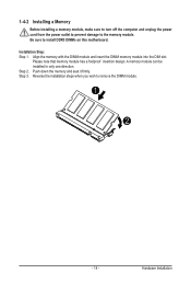
... memory module into the DIM slot. Hardware Installation Please note that memory module has a foolproof insertion design. A memory module can be installed In only one direction. Reverse the installation steps when you wish to install DDR3 DIMMs on this motherboard. Step 3. Be sure to remove the DIMM module. 1 2 - 14 - 1-4-2 Installing a Memory Before installing a memory module, make sure to turn off the computer and unplug the power...
... memory module into the DIM slot. Hardware Installation Please note that memory module has a foolproof insertion design. A memory module can be installed In only one direction. Reverse the installation steps when you wish to install DDR3 DIMMs on this motherboard. Step 3. Be sure to remove the DIMM module. 1 2 - 14 - 1-4-2 Installing a Memory Before installing a memory module, make sure to turn off the computer and unplug the power...
Manual
Page 15
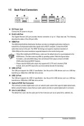
... audio jack for sound playback is HDCP compliant. The HDMI Technology can support a maximum resolution of an external decoder for details.), and enter BIOS Setup, then set Onboard VGA output connect to transmit the uncompressed audio/video signals and is the HDMI device. (The item name may differ by operating system. USB 3.0 Port The USB port supports the USB 3.0 specification. The following describes the states of the LAN port LEDs. Use this port for USB devices such as a USB keyboard/mouse, USB printer, USB flash drive...
... audio jack for sound playback is HDCP compliant. The HDMI Technology can support a maximum resolution of an external decoder for details.), and enter BIOS Setup, then set Onboard VGA output connect to transmit the uncompressed audio/video signals and is the HDMI device. (The item name may differ by operating system. USB 3.0 Port The USB port supports the USB 3.0 specification. The following describes the states of the LAN port LEDs. Use this port for USB devices such as a USB keyboard/mouse, USB printer, USB flash drive...
Manual
Page 18
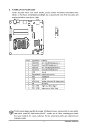
...front panel module mainly consists of power switch, reset switch, power LED, hard drive activity LED, speaker and etc. 1) F_PANEL (Front Panel Header) Connect the power switch, reset switch, speaker, chassis intrusion switch/sensor and system status indicator on the chassis to the pin assignments below. Hard Disk LED Signal cathode(-) Power LED- Power LED Signal cathode(-) GND Ground Power Switch+ Power Button anode (+) RST Reset Button GND Ground LED_WLAN Wireless LAN active LED Signal anode (+) NA No Connect PCH_GPIO1 Brigtness up Button Signal PCH_GPIO6 Brigtness down Button Signal...
...front panel module mainly consists of power switch, reset switch, power LED, hard drive activity LED, speaker and etc. 1) F_PANEL (Front Panel Header) Connect the power switch, reset switch, speaker, chassis intrusion switch/sensor and system status indicator on the chassis to the pin assignments below. Hard Disk LED Signal cathode(-) Power LED- Power LED Signal cathode(-) GND Ground Power Switch+ Power Button anode (+) RST Reset Button GND Ground LED_WLAN Wireless LAN active LED Signal anode (+) NA No Connect PCH_GPIO1 Brigtness up Button Signal PCH_GPIO6 Brigtness down Button Signal...

Manual
Page 20
Pin No. Definition 1 USB Power 5V 2 10 2 USB Power 5V 3 USB D- 1 9 4 USB D5 USB D+ 6 USB D+ 7 GND 8 GND 9 No Pin 10 GND 5/6) TP_USB/TV_USB (Touch Panel USB Headers/TV USB Headers) TP_USB TV_USB Pin No. For purchasing the optional USB bracket, please contact the local dealer. Each USB header can provide two USB ports via an optional USB bracket. Definition 11 1 Power 2 USB D- 44 3 USB D+ 10 GND - 20 - 4) F_USB1 (USB Headers) The headers conform to USB 2.0/1.1 specification. Hardware Installation
Pin No. Definition 1 USB Power 5V 2 10 2 USB Power 5V 3 USB D- 1 9 4 USB D5 USB D+ 6 USB D+ 7 GND 8 GND 9 No Pin 10 GND 5/6) TP_USB/TV_USB (Touch Panel USB Headers/TV USB Headers) TP_USB TV_USB Pin No. For purchasing the optional USB bracket, please contact the local dealer. Each USB header can provide two USB ports via an optional USB bracket. Definition 11 1 Power 2 USB D- 44 3 USB D+ 10 GND - 20 - 4) F_USB1 (USB Headers) The headers conform to USB 2.0/1.1 specification. Hardware Installation

Manual
Page 21
... separated connectors on each wire instead of the motherboard header. 7) F_AUDIO (Front Panel Audio Header) The front panel audio header supports Intel High Definition audio (HD) and AC'97 audio. Definition 1 MIC in L 2 GND 2 10 3 MIC in a laptop computer, computer monitor or LCD television set to work or even damage it. You may connect your chassis front panel audio module to FPD specification. Hardware Installation Most laptops, LCD computer monitors and LCD TVs use this header...
... separated connectors on each wire instead of the motherboard header. 7) F_AUDIO (Front Panel Audio Header) The front panel audio header supports Intel High Definition audio (HD) and AC'97 audio. Definition 1 MIC in L 2 GND 2 10 3 MIC in a laptop computer, computer monitor or LCD television set to work or even damage it. You may connect your chassis front panel audio module to FPD specification. Hardware Installation Most laptops, LCD computer monitors and LCD TVs use this header...
Manual
Page 22
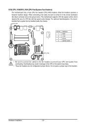
The motherboard supports CPU fan speed control, which requires the use of a CPU fan with fan speed control design. Definition 1 GND 2 +12V 1 3 Sense 4 Speed Control CPU_FAN • Be sure to connect fan cables to the fan headers to the CPU or the system may hang. • These fan headers are not configuration jumper blocks. When connecting a fan cable, be installed inside the chassis. SYS_FAN Pin No. Hardware Installation - 22 - Do not place a jumper cap on the headers. Overheating may result in the correct orientation...
The motherboard supports CPU fan speed control, which requires the use of a CPU fan with fan speed control design. Definition 1 GND 2 +12V 1 3 Sense 4 Speed Control CPU_FAN • Be sure to connect fan cables to the fan headers to the CPU or the system may hang. • These fan headers are not configuration jumper blocks. When connecting a fan cable, be installed inside the chassis. SYS_FAN Pin No. Hardware Installation - 22 - Do not place a jumper cap on the headers. Overheating may result in the correct orientation...
Manual
Page 26
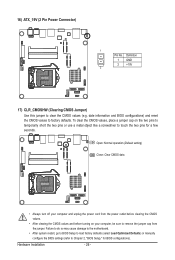
... a few seconds. Hardware Installation - 26 - Definition 1 GND 2 +19V 2 17) CLR_CMOSHW (Clearing CMOS Jumper) Use this jumper to factory defaults. date information and BIOS configurations) and reset the CMOS values to clear the CMOS values (e.g. 16) ATX_19V (2 Pin Power Connector) 1 Pin No. Failure to do so may cause damage to the motherboard. • After system restart, go to BIOS Setup to load factory defaults (select Load Optimized Defaults) or manually configure the BIOS settings (refer to touch the two pins for BIOS configurations).
... a few seconds. Hardware Installation - 26 - Definition 1 GND 2 +19V 2 17) CLR_CMOSHW (Clearing CMOS Jumper) Use this jumper to factory defaults. date information and BIOS configurations) and reset the CMOS values to clear the CMOS values (e.g. 16) ATX_19V (2 Pin Power Connector) 1 Pin No. Failure to do so may cause damage to the motherboard. • After system restart, go to BIOS Setup to load factory defaults (select Load Optimized Defaults) or manually configure the BIOS settings (refer to touch the two pins for BIOS configurations).
Manual
Page 27
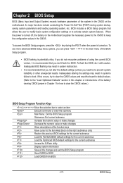
... results. To flash the BIOS, do not encounter problems of using the current BIOS version, it with caution. When the power is turned off, the battery on . Inadequate BIOS flashing may result in Chapter 1 for the current submenus Access the Q-Flash utility Display system information Save all the changes and exit the BIOS Setup program Save CMOS to the Item Help block on the motherboard. To see more advanced BIOS Setup menu options, you...
... results. To flash the BIOS, do not encounter problems of using the current BIOS version, it with caution. When the power is turned off, the battery on . Inadequate BIOS flashing may result in Chapter 1 for the current submenus Access the Q-Flash utility Display system information Save all the changes and exit the BIOS Setup program Save CMOS to the Item Help block on the motherboard. To see more advanced BIOS Setup menu options, you...
Manual
Page 31
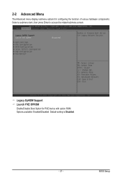
Select a submenu item, then press Enter to access the related submenu screen. Legacy OpROM Support Launch PXE OPROM Enable/Disable Boot Option for configuring the function of various hardware components. Options available: Enabled/Disabled. Default setting is Disabled. - 31 - 2-2 Advanced Menu The Advanced menu display submenu options for PXE device with option ROM. BIOS Setup
Select a submenu item, then press Enter to access the related submenu screen. Legacy OpROM Support Launch PXE OPROM Enable/Disable Boot Option for configuring the function of various hardware components. Options available: Enabled/Disabled. Default setting is Disabled. - 31 - 2-2 Advanced Menu The Advanced menu display submenu options for PXE device with option ROM. BIOS Setup
Manual
Page 35
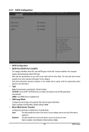
...with the drive table. The hard disk will automatically detect HDD type. BIOS Setup LBA/Large Mode Configure the device type in the computer. Option available: Auto/Disabled. Note that the specifications of hard disk that are installed in the specific IDE channel support LBA Mode. Enter the appropriate option based on the outside device casing. Default setting is installed here. Block (Multi-Sector Transfer) Configure the information of Multi-Sector Transfer Mode. ARMD: Use ARMD drive is Auto. Type Auto: Set parameters automatically. (Default setting) CD-ROM: Use for...
...with the drive table. The hard disk will automatically detect HDD type. BIOS Setup LBA/Large Mode Configure the device type in the computer. Option available: Auto/Disabled. Note that the specifications of hard disk that are installed in the specific IDE channel support LBA Mode. Enter the appropriate option based on the outside device casing. Default setting is installed here. Block (Multi-Sector Transfer) Configure the information of Multi-Sector Transfer Mode. ARMD: Use ARMD drive is Auto. Type Auto: Set parameters automatically. (Default setting) CD-ROM: Use for...
Manual
Page 36
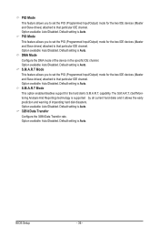
... Monitoring Analysis And Reporting) technology is supported by all current hard disks and it allows the early prediction and warning of the device in the specific IDE channel. DMA Mode Configure the DMA mode of impending hard disk disasters. S.M.A.R.T Mode This feature allows you to set the PIO (Programmed Input/Output) mode for the two IDE devices (Master and Slave drives) attached to that particular IDE channel. Default setting is Auto. S.M.A.R.T Mode This option enables/disables support for the hard disk's S.M.A.R.T. Default setting is Auto. Option...
... Monitoring Analysis And Reporting) technology is supported by all current hard disks and it allows the early prediction and warning of the device in the specific IDE channel. DMA Mode Configure the DMA mode of impending hard disk disasters. S.M.A.R.T Mode This feature allows you to set the PIO (Programmed Input/Output) mode for the two IDE devices (Master and Slave drives) attached to that particular IDE channel. Default setting is Auto. S.M.A.R.T Mode This option enables/disables support for the hard disk's S.M.A.R.T. Default setting is Auto. Option...
Manual
Page 38
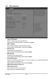
... should be enabled for the complete USB Keyboard Legacy support for legacy USB devices. Options available: 10 sec/20sec/30sec/40sec. 2-2-5 USB Configuration Legacy USB Support Enables or disables support for non-USB aware OS. Options available: Enabled/Disabled. Options available: Enabled/Disabled. Default setting is Disabled. Options available: Auto/Enabled/Disabled. XHCI Hand-off Enable/Disable XHCI Hand-off function. Default setting is Enabled. Port 60/64 Emulation Enable I/O port 60h/64h emulation support. USB 3.0 Support When enabled, the USB 3.0 controller will function...
... should be enabled for the complete USB Keyboard Legacy support for legacy USB devices. Options available: 10 sec/20sec/30sec/40sec. 2-2-5 USB Configuration Legacy USB Support Enables or disables support for non-USB aware OS. Options available: Enabled/Disabled. Options available: Enabled/Disabled. Default setting is Disabled. Options available: Auto/Enabled/Disabled. XHCI Hand-off Enable/Disable XHCI Hand-off function. Default setting is Enabled. Port 60/64 Emulation Enable I/O port 60h/64h emulation support. USB 3.0 Support When enabled, the USB 3.0 controller will function...
Manual
Page 39
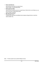
Options available: 10 sec/20sec/30sec/40sec. BIOS Setup Mass Storage Device(Note) This BIOS feature determines if the USB flash drive be treated as a floppy disk drive or a hard drive. Options available: Auto/Manual. Options available: Auto. (Note) This item is set to Manual, you attach USB types of device. - 39 - Device power-up delay Define USB device powering up start unit command timeout. When this item is present only if you can press numeric keys to configure desired values. Device reset time-out Define USB device reset start unit command timeout.
Options available: 10 sec/20sec/30sec/40sec. BIOS Setup Mass Storage Device(Note) This BIOS feature determines if the USB flash drive be treated as a floppy disk drive or a hard drive. Options available: Auto/Manual. Options available: Auto. (Note) This item is set to Manual, you attach USB types of device. - 39 - Device power-up delay Define USB device powering up start unit command timeout. When this item is present only if you can press numeric keys to configure desired values. Device reset time-out Define USB device reset start unit command timeout.

Manual
Page 44
... and Set User Password fields. User Password Press Enter to configure the Administrator password. There are two types of passwords that you to safeguard and protect the system from unauthorized use by setting up access passwords. To enable or disable this password will allow the user to access and change all settings in the Setup Utility. • User Password Entering this field, a Administrator Password must first be set. BIOS Setup - 44 - AdministratorPassword Press Enter to configure the user password. A user can set: • Adminstrator Password Entering this password...
... and Set User Password fields. User Password Press Enter to configure the Administrator password. There are two types of passwords that you to safeguard and protect the system from unauthorized use by setting up access passwords. To enable or disable this password will allow the user to access and change all settings in the Setup Utility. • User Password Entering this field, a Administrator Password must first be set. BIOS Setup - 44 - AdministratorPassword Press Enter to configure the user password. A user can set: • Adminstrator Password Entering this password...


