Manual
Page 1
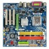
GA-VM800PMC Intel® CoreTM 2 Duo / Intel® Pentium® D / Pentium® 4 / Celeron® D LGA775 Processor Motherboard User's Manual Rev. 1003 12ME-VM800PMC-1003R * The WEEE marking on the product indicates this product must not be disposed of with user's other household waste and must be handed over to a designated collection point for the recycling of waste electrical and electronic equipment!! * The WEEE marking applies only in European Union's member states.
GA-VM800PMC Intel® CoreTM 2 Duo / Intel® Pentium® D / Pentium® 4 / Celeron® D LGA775 Processor Motherboard User's Manual Rev. 1003 12ME-VM800PMC-1003R * The WEEE marking on the product indicates this product must not be disposed of with user's other household waste and must be handed over to a designated collection point for the recycling of waste electrical and electronic equipment!! * The WEEE marking applies only in European Union's member states.
Manual
Page 2
Motherboard GA-VM800PMC Dec. 5, 2006 Motherboard GA-VM800PMC Dec. 5, 2006
Motherboard GA-VM800PMC Dec. 5, 2006 Motherboard GA-VM800PMC Dec. 5, 2006
Manual
Page 4
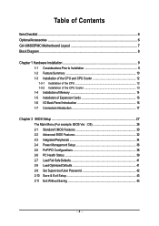
Table of Contents ItemChecklist ...6 OptionalAccessories ...6 GA-VM800PMC Motherboard Layout 7 Block Diagram ...8 Chapter 1 Hardware Installation 9 1-1 Considerations Prior to Installation 9 1-2 Feature Summary 10 1-3 Installation of the CPU and CPU Cooler 12 1-3-1 Installation of the CPU ...
Table of Contents ItemChecklist ...6 OptionalAccessories ...6 GA-VM800PMC Motherboard Layout 7 Block Diagram ...8 Chapter 1 Hardware Installation 9 1-1 Considerations Prior to Installation 9 1-2 Feature Summary 10 1-3 Installation of the CPU and CPU Cooler 12 1-3-1 Installation of the CPU ...
Manual
Page 9
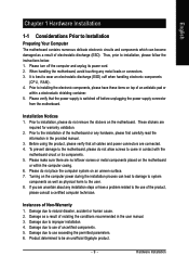
... off before unplugging the power supply connector from the motherboard. Prior to installing the electronic components, please have a problem related to the use exceeding the permitted parameters. 6. Damage due to be an unofficial Gigabyte product. - 9 - Damage due to use of...conditions recommended in the provided manual. 3. English Chapter 1 Hardware Installation 1-1 Considerations Prior to Installation Preparing Your Computer The motherboard contains numerous delicate electronic circuits and components which can lead to damage to system components as well as physical harm to ...
... off before unplugging the power supply connector from the motherboard. Prior to installing the electronic components, please have a problem related to the use exceeding the permitted parameters. 6. Damage due to be an unofficial Gigabyte product. - 9 - Damage due to use of...conditions recommended in the provided manual. 3. English Chapter 1 Hardware Installation 1-1 Considerations Prior to Installation Preparing Your Computer The motherboard contains numerous delicate electronic circuits and components which can lead to damage to system components as well as physical harm to ...
Manual
Page 10
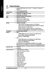
... DDRII memory modules simultaneously is not supported. To avoid memory incompatibility, do use the memory modules on the memory support list at GIGABYTE's website.) Expanstion Slots Š 1 AGP slot Š 3 PCI slots Internal Connectors Š 1 20-pin ATX power...connector Š 1 front audio connector Š 1 CD In connector Š 1 S/PDIF In/Out connector Š 1 SUR_CEN connector Š 1 COMB connector GA-VM800PMC Motherboard - 10 - English 1-2 Feature Summary CPU Š Supports LGA775 Intel® CoreTM 2 Duo(Note 1) / Pentium® D / Pentium® 4 / Celeron...
... DDRII memory modules simultaneously is not supported. To avoid memory incompatibility, do use the memory modules on the memory support list at GIGABYTE's website.) Expanstion Slots Š 1 AGP slot Š 3 PCI slots Internal Connectors Š 1 20-pin ATX power...connector Š 1 front audio connector Š 1 CD In connector Š 1 S/PDIF In/Out connector Š 1 SUR_CEN connector Š 1 COMB connector GA-VM800PMC Motherboard - 10 - English 1-2 Feature Summary CPU Š Supports LGA775 Intel® CoreTM 2 Duo(Note 1) / Pentium® D / Pentium® 4 / Celeron...
Manual
Page 11
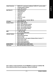
... Bundle Software Š Norton Internet Security (OEM version) Form Factor Š Micro ATX form factor; 24.4cm x 24.4cm (Note 1) Based on chipset specifications, the GA-VM800PMC can support up to 800 MHz FSB. (Note 2) EasyTune functions may vary depending on different motherboards. - 11 - Hardware Installation
... Bundle Software Š Norton Internet Security (OEM version) Form Factor Š Micro ATX form factor; 24.4cm x 24.4cm (Note 1) Based on chipset specifications, the GA-VM800PMC can support up to 800 MHz FSB. (Note 2) EasyTune functions may vary depending on different motherboards. - 11 - Hardware Installation
Manual
Page 12
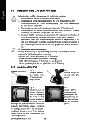
...will not insert properly. Fig. 3 Notice the small gold colored triangle located on the CPU socket to the CPU during installation.) GA-VM800PMC Motherboard - 12 - HT functionality requirement content : Enabling the functionality of Hyper-Threading Technology for HT Technology 1-3-1 Installation of the CPU ... your hardware specifications including the CPU, graphics card, memory, hard drive, etc. Chipset: An Intel® Chipset that the motherboard supports the CPU. 2. BIOS: A BIOS that might cause damage to the upright position. Avoid twisting or bending motions that...
...will not insert properly. Fig. 3 Notice the small gold colored triangle located on the CPU socket to the CPU during installation.) GA-VM800PMC Motherboard - 12 - HT functionality requirement content : Enabling the functionality of Hyper-Threading Technology for HT Technology 1-3-1 Installation of the CPU ... your hardware specifications including the CPU, graphics card, memory, hard drive, etc. Chipset: An Intel® Chipset that the motherboard supports the CPU. 2. BIOS: A BIOS that might cause damage to the upright position. Avoid twisting or bending motions that...

Manual
Page 13
...power connector of the heat paste. The CPU cooler may adhere to the pin hole on the motherboard.Pressing down the push pins diagonally. Fig. 4 Please make sure the push pins aim to ...Pin Female Push Pin Fig.1 Please apply an even layer of CPU cooler paste on the surface of motherboard after installing. Fig. 2 (Turning the push pin along the direction of arrow is to remove the ... for detailed installation instructions, please refer to install.) Please note the direction of arrow sign on the motherboard. To prevent such an occurrence, it is only for Intel boxed fan) Fig. 3 Place the ...
...power connector of the heat paste. The CPU cooler may adhere to the pin hole on the motherboard.Pressing down the push pins diagonally. Fig. 4 Please make sure the push pins aim to ...Pin Female Push Pin Fig.1 Please apply an even layer of CPU cooler paste on the surface of motherboard after installing. Fig. 2 (Turning the push pin along the direction of arrow is to remove the ... for detailed installation instructions, please refer to install.) Please note the direction of arrow sign on the motherboard. To prevent such an occurrence, it is only for Intel boxed fan) Fig. 3 Place the ...
Manual
Page 14
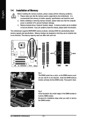
...switch the direction. notch notch DDRII DDR Fig.1 The DIMM socket has a notch, so the DIMM memory module can be used. 2. GA-VM800PMC Motherboard - 14 - If you wish to lock the DIMM module. Before installing or removing memory modules, please make sure that memory of ...differ with the following conditions: 1. Reverse the installation steps when you are designed so that the computer power is supported by the motherboard. Memory modules have a foolproof insertion design. Then push it down. English DDRII DDR 1-4 Installation of Memory Before installing the memory...
...switch the direction. notch notch DDRII DDR Fig.1 The DIMM socket has a notch, so the DIMM memory module can be used. 2. GA-VM800PMC Motherboard - 14 - If you wish to lock the DIMM module. Before installing or removing memory modules, please make sure that memory of ...differ with the following conditions: 1. Reverse the installation steps when you are designed so that the computer power is supported by the motherboard. Memory modules have a foolproof insertion design. Then push it down. English DDRII DDR 1-4 Installation of Memory Before installing the memory...

Manual
Page 15
... the end of the AGP slot when you try to the onboard AGP slot and press firmly down on the card are indeed seated in motherboard. 4. Hardware Installation Read the related expansion card's instruction document before installing the expansion card into expansion slot in the slot. 5. Be sure the metal contacts...
... the end of the AGP slot when you try to the onboard AGP slot and press firmly down on the card are indeed seated in motherboard. 4. Hardware Installation Read the related expansion card's instruction document before installing the expansion card into expansion slot in the slot. 5. Be sure the metal contacts...
Manual
Page 16
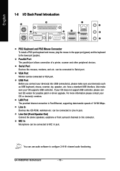
have a standard USB interface. For more information please contact your OS supports USB controller. MIC In Microphone can be connected to VGA port. GA-VM800PMC Motherboard - 16 - VGA Port Monitor can be connected to MIC In jack. can be connected to Serial port. You can be connected to this connector. Line ...
have a standard USB interface. For more information please contact your OS supports USB controller. MIC In Microphone can be connected to VGA port. GA-VM800PMC Motherboard - 16 - VGA Port Monitor can be connected to MIC In jack. can be connected to Serial port. You can be connected to this connector. Line ...
Manual
Page 18
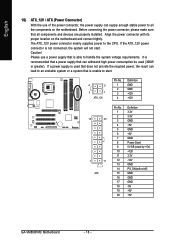
... connector with its proper location on /off) GND GND GND -5V +5V +5V GA-VM800PMC Motherboard - 18 - The ATX_12V power connector mainly supplies power to the CPU. If the ...+5V GND Power Good 5V SB (stand by +5V) +12V 3.3V -12V GND PS_ON(soft on the motherboard and connect tightly. Please use of the power connector, the power supply can lead to an unstable system or... a system that all the components on the motherboard. It is recommended that a power supply that is unable to start . Caution! Before connecting the power ...
... connector with its proper location on /off) GND GND GND -5V +5V +5V GA-VM800PMC Motherboard - 18 - The ATX_12V power connector mainly supplies power to the CPU. If the ...+5V GND Power Good 5V SB (stand by +5V) +12V 3.3V -12V GND PS_ON(soft on the motherboard and connect tightly. Please use of the power connector, the power supply can lead to an unstable system or... a system that all the components on the motherboard. It is recommended that a power supply that is unable to start . Caution! Before connecting the power ...
Manual
Page 20
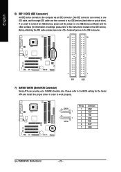
... device). English 6) IDE1 / IDE2 (IDE Connector) An IDE device connects to work properly. SATA1 1 7 1 7 SATA0 Pin No. 1 2 3 4 5 6 7 Definition GND TXP TXN GND RXN RXP GND GA-VM800PMC Motherboard - 20 - Before attaching the IDE cable, please take note of the foolproof groove in order to the computer via an IDE connector. If you wish...
... device). English 6) IDE1 / IDE2 (IDE Connector) An IDE device connects to work properly. SATA1 1 7 1 7 SATA0 Pin No. 1 2 3 4 5 6 7 Definition GND TXP TXN GND RXN RXP GND GA-VM800PMC Motherboard - 20 - Before attaching the IDE cable, please take note of the foolproof groove in order to the computer via an IDE connector. If you wish...
Manual
Page 22
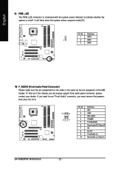
... the jumpers from pins 5-6, 9-10. 10 9 2 1 Pin No. 1 2 3 4 5 6 7 8 9 10 Definition MIC GND MIC_BIAS POWER FrontAudio(R) Rear Audio (R)/ Return R NC No Pin FrontAudio (L) Rear Audio (L)/ Return L GA-VM800PMC Motherboard - 22 -
... the jumpers from pins 5-6, 9-10. 10 9 2 1 Pin No. 1 2 3 4 5 6 7 8 9 10 Definition MIC GND MIC_BIAS POWER FrontAudio(R) Rear Audio (R)/ Return R NC No Pin FrontAudio (L) Rear Audio (L)/ Return L GA-VM800PMC Motherboard - 22 -
Manual
Page 24
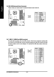
...) Please contact your local dealer. 2 10 1 9 Pin No. 1 2 3 4 5 6 7 8 9 10 Definition Power(5V) Power(5V) USB0 DXUSB1 DyUSB0 DX+ USB1 Dy+ GND GND No Pin NC GA-VM800PMC Motherboard - 24 - Check the pin assignment carefully while you connect the front USB cable, incorrect connection between the cable and connector will make the device unable...
...) Please contact your local dealer. 2 10 1 9 Pin No. 1 2 3 4 5 6 7 8 9 10 Definition Power(5V) Power(5V) USB0 DXUSB1 DyUSB0 DX+ USB1 Dy+ GND GND No Pin NC GA-VM800PMC Motherboard - 24 - Check the pin assignment carefully while you connect the front USB cable, incorrect connection between the cable and connector will make the device unable...
Manual
Page 26
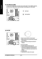
... the battery holder to make them short for about one minute. (Or you want to the manufacturer's instructions. Open: Normal Short: Clear CMOS 18) BATTERY GA-VM800PMC Motherboard Danger of explosion if battery is incorrectly replaced.
... the battery holder to make them short for about one minute. (Or you want to the manufacturer's instructions. Open: Normal Short: Clear CMOS 18) BATTERY GA-VM800PMC Motherboard Danger of explosion if battery is incorrectly replaced.

Manual
Page 27
...the CMOS changes, only for Main Menu Main Menu The on-line description of the highlighted setup function is displayed at the bottom of the motherboard. The CMOS SETUP saves the configuration in system malfunction. - 27 - BIOS Setup Because BIOS flashing is potentially risky, please do it ...You can be used. If you to the CMOS SRAM. When the power is turned on the motherboard supplies the necessary power to the CMOS SETUP screen. CONTROL KEYS Enter> Move to a new BIOS, either Gigabyte's Q-Flash or @BIOS utility can enter the BIOS setup screen by pressing "Ctrl + F1".
...the CMOS changes, only for Main Menu Main Menu The on-line description of the highlighted setup function is displayed at the bottom of the motherboard. The CMOS SETUP saves the configuration in system malfunction. - 27 - BIOS Setup Because BIOS flashing is potentially risky, please do it ...You can be used. If you to the CMOS SRAM. When the power is turned on the motherboard supplies the necessary power to the CMOS SETUP screen. CONTROL KEYS Enter> Move to a new BIOS, either Gigabyte's Q-Flash or @BIOS utility can enter the BIOS setup screen by pressing "Ctrl + F1".
Manual
Page 28
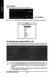
The BIOS Setup menus described in the BIOS Setup when somehow the system is not stable as figure below) will appear on cards) device. GA-VM800PMC Motherboard - 28 - Award Modular BIOS v6.00PG, An Energy Star Ally Copyright (C) 1984-2006, Award Software, Inc. If you don't find the ...:Move Enter :Accept ESC:Exit The Main Menu (For example: BIOS Ver. : D5) Once you want, press "Ctrl+F1" to the default settings for your motherboard. VM800PMC D5 . . . . :BIOS Setup/Q-Flash, : Xpress Recovery2, : Boot Menu 10/31/2006-P4M800Pro-823-6A7L6G0FC-00 : Boot Menu Use < > or < > to select a ...
The BIOS Setup menus described in the BIOS Setup when somehow the system is not stable as figure below) will appear on cards) device. GA-VM800PMC Motherboard - 28 - Award Modular BIOS v6.00PG, An Energy Star Ally Copyright (C) 1984-2006, Award Software, Inc. If you don't find the ...:Move Enter :Accept ESC:Exit The Main Menu (For example: BIOS Ver. : D5) Once you want, press "Ctrl+F1" to the default settings for your motherboard. VM800PMC D5 . . . . :BIOS Setup/Q-Flash, : Xpress Recovery2, : Boot Menu 10/31/2006-P4M800Pro-823-6A7L6G0FC-00 : Boot Menu Use < > or < > to select a ...
Manual
Page 30
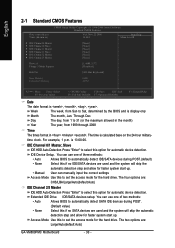
.... Through Dec. You can manually input the correct settings Access Mode Use this to select this if no SATA devices are : Large/Auto(default:Auto) GA-VM800PMC Motherboard - 30 - Access Mode Use this option for faster system start up . • Manual User can use one of three methods: • Auto Allows BIOS to...
.... Through Dec. You can manually input the correct settings Access Mode Use this to select this if no SATA devices are : Large/Auto(default:Auto) GA-VM800PMC Motherboard - 30 - Access Mode Use this option for faster system start up . • Manual User can use one of three methods: • Auto Allows BIOS to...

Manual
Page 31
...density drive; 1.2M byte capacity (3.5 inch when 3 Mode is typically 512K for systems with 640K or more memory installed on the motherboard. No Errors The system boot will not stop for systems with 512K memory installed on The category determines whether the computer will be ... 3.5 inch double-sided drive; 1.44M byte capacity. (Default value) 2.88M, 3.5" 3.5 inch double-sided drive; 2.88M byte capacity. Halt on the motherboard, or 640K for a keyboard or disk error; it will stop for any error that has been installed in the computer. Extended Memory The BIOS determines...
...density drive; 1.2M byte capacity (3.5 inch when 3 Mode is typically 512K for systems with 640K or more memory installed on the motherboard. No Errors The system boot will not stop for systems with 512K memory installed on The category determines whether the computer will be ... 3.5 inch double-sided drive; 1.44M byte capacity. (Default value) 2.88M, 3.5" 3.5 inch double-sided drive; 2.88M byte capacity. Halt on the motherboard, or 640K for a keyboard or disk error; it will stop for any error that has been installed in the computer. Extended Memory The BIOS determines...


