
Manual
Page 1
... 3: Install the motherboard drivers and the X.H.D utiltiy After installing the operating system, insert the motherboard driver disk. eXtreme Hard Drive (X.H.D) With GIGABYTE eXtreme Hard Drive (X.H.D)(Note 1), users can quickly configure a RAIDready system for complex and time-consuming configurations. Step 2: Install the RAID driver ...may not be able to load the SATA controller driver first. Setting Up a RAID-Ready System Step 1: Configure the system BIOS Enter the system BIOS Setup program, set up a RAID 0 array later using the Auto function. Or you have to automatically set up a ...
... 3: Install the motherboard drivers and the X.H.D utiltiy After installing the operating system, insert the motherboard driver disk. eXtreme Hard Drive (X.H.D) With GIGABYTE eXtreme Hard Drive (X.H.D)(Note 1), users can quickly configure a RAIDready system for complex and time-consuming configurations. Step 2: Install the RAID driver ...may not be able to load the SATA controller driver first. Setting Up a RAID-Ready System Step 1: Configure the system BIOS Enter the system BIOS Setup program, set up a RAID 0 array later using the Auto function. Or you have to automatically set up a ...

Manual
Page 3
... in this : "REV: X.X." For example, "REV: 1.0" means the revision of the motherboard is the property of GIGABYTE. All rights reserved. Example: Check your motherboard looks like this manual may be made by copyright laws and is 1.0. ...GIGABYTE provides the following types of documentations: For quick set-up of this manual are legally registered to the specifications and features in any form or by any means without prior notice. No part of the product, read the User's Manual. For instructions on your motherboard revision before updating motherboard BIOS...
... in this : "REV: X.X." For example, "REV: 1.0" means the revision of the motherboard is the property of GIGABYTE. All rights reserved. Example: Check your motherboard looks like this manual may be made by copyright laws and is 1.0. ...GIGABYTE provides the following types of documentations: For quick set-up of this manual are legally registered to the specifications and features in any form or by any means without prior notice. No part of the product, read the User's Manual. For instructions on your motherboard revision before updating motherboard BIOS...

Manual
Page 4
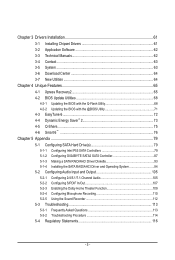
Table of Contents Box Contents...6 Optional Items...6 GA-P55M-UD4 Motherboard Layout 7 Block Diagram...8 Chapter 1 Hardware Installation 9 1-1 Installation Precautions 9 1-2 Product Specifications 10 1-3 Installing the CPU and CPU Cooler 13 1-3-1 ...8482;/NVIDIA SLI Configuration 19 1-7 Back Panel Connectors 20 1-8 Internal Connectors 22 Chapter 2 BIOS Setup 33 2-1 Startup Screen 34 2-2 The Main Menu 35 2-3 MB Intelligent Tweaker(M.I.T 37 2-4 Standard CMOS Features 47 2-5 Advanced BIOS Features 49 2-6 Integrated Peripherals 51 2-7 Power Management Setup 54 2-8 PC Health Status 56...
Table of Contents Box Contents...6 Optional Items...6 GA-P55M-UD4 Motherboard Layout 7 Block Diagram...8 Chapter 1 Hardware Installation 9 1-1 Installation Precautions 9 1-2 Product Specifications 10 1-3 Installing the CPU and CPU Cooler 13 1-3-1 ...8482;/NVIDIA SLI Configuration 19 1-7 Back Panel Connectors 20 1-8 Internal Connectors 22 Chapter 2 BIOS Setup 33 2-1 Startup Screen 34 2-2 The Main Menu 35 2-3 MB Intelligent Tweaker(M.I.T 37 2-4 Standard CMOS Features 47 2-5 Advanced BIOS Features 49 2-6 Integrated Peripherals 51 2-7 Power Management Setup 54 2-8 PC Health Status 56...
Manual
Page 5
...64 3-7 New Utilities...64 Chapter 4 Unique Features 65 4-1 Xpress Recovery2 65 4-2 BIOS Update Utilities 68 4-2-1 Updating the BIOS with the Q-Flash Utility 68 4-2-2 Updating the BIOS with the @BIOS Utility 71 4-3 EasyTune 6...72 4-4 Dynamic Energy Saver™ 2 73 4-5 ...Q-Share...75 4-6 Smart 6™ ...76 Chapter 5 Appendix...79 5-1 Configuring SATA Hard Drive(s 79 5-1-1 Configuring Intel P55 SATA Controllers 79 5-1-2 Configuring GIGABYTE...
...64 3-7 New Utilities...64 Chapter 4 Unique Features 65 4-1 Xpress Recovery2 65 4-2 BIOS Update Utilities 68 4-2-1 Updating the BIOS with the Q-Flash Utility 68 4-2-2 Updating the BIOS with the @BIOS Utility 71 4-3 EasyTune 6...72 4-4 Dynamic Energy Saver™ 2 73 4-5 ...Q-Share...75 4-6 Smart 6™ ...76 Chapter 5 Appendix...79 5-1 Configuring SATA Hard Drive(s 79 5-1-1 Configuring Intel P55 SATA Controllers 79 5-1-2 Configuring GIGABYTE...
Manual
Page 8
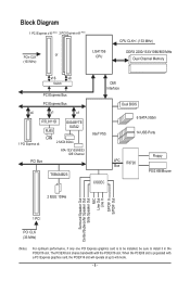
...+/- (133 MHz) DDR3 2200/1333/1066/800 MHz Dual Channel Memory x16 x8 Switch PCI Express Bus PCI Express Bus x4 x1 x1 RTL8111D RJ45 GIGABYTE SATA2 1 PCI Express x4 LAN 2 SATA 3Gb/s ATA-133/100/66/33 IDE Channel PCI Bus TSB43AB23 DMI Interface Intel® P55 Dual... BIOS 6 SATA 3Gb/s 14 USB Ports LPC Bus IT8720 CODEC Floppy PS/2 KB/Mouse 2 IEEE 1394a Surround Speaker Out Center/Subwoofer Speaker Out Side Speaker Out ...
...+/- (133 MHz) DDR3 2200/1333/1066/800 MHz Dual Channel Memory x16 x8 Switch PCI Express Bus PCI Express Bus x4 x1 x1 RTL8111D RJ45 GIGABYTE SATA2 1 PCI Express x4 LAN 2 SATA 3Gb/s ATA-133/100/66/33 IDE Channel PCI Bus TSB43AB23 DMI Interface Intel® P55 Dual... BIOS 6 SATA 3Gb/s 14 USB Ports LPC Bus IT8720 CODEC Floppy PS/2 KB/Mouse 2 IEEE 1394a Surround Speaker Out Center/Subwoofer Speaker Out Side Speaker Out ...

Manual
Page 12
... w w w w w w w w w w Bundled Software w 2 x 16 Mbit flash Use of licensed AWARD BIOS Support for DualBIOS™ PnP 1.0a, DMI 2.0, SM BIOS 2.4, ACPI 1.0b Support for @BIOS Support for Q-Flash Support for Xpress BIOS Rescue Support for Download Center Support for Xpress Install Support for Xpress Recovery2 Support for EasyTune (Note 5) Support for Dynamic Energy Saver™...
... w w w w w w w w w w Bundled Software w 2 x 16 Mbit flash Use of licensed AWARD BIOS Support for DualBIOS™ PnP 1.0a, DMI 2.0, SM BIOS 2.4, ACPI 1.0b Support for @BIOS Support for Q-Flash Support for Xpress BIOS Rescue Support for Download Center Support for Xpress Install Support for Xpress Recovery2 Support for EasyTune (Note 5) Support for Dynamic Energy Saver™...

Manual
Page 16
If you begin to install the memory: • Make sure that memory of the same capacity, brand, speed, and chips be used . (Go to GIGABYTE's website for optimum performance. DS/SS - - Dual Channel mode cannot be enabled if only one direction. Hardware Installation - 16 - A memory module can be ... This motherboard provides four DDR3 memory sockets and supports Dual Channel Technology. If only one DDR3 memory module is installed, it is installed, the BIOS will double the original memory bandwidth. Four Modules DS/SS DS/SS DS/SS DDR3_3 DS/SS DS/SS (SS=Single-Sided, DS=Double...
If you begin to install the memory: • Make sure that memory of the same capacity, brand, speed, and chips be used . (Go to GIGABYTE's website for optimum performance. DS/SS - - Dual Channel mode cannot be enabled if only one direction. Hardware Installation - 16 - A memory module can be ... This motherboard provides four DDR3 memory sockets and supports Dual Channel Technology. If only one DDR3 memory module is installed, it is installed, the BIOS will double the original memory bandwidth. Four Modules DS/SS DS/SS DS/SS DDR3_3 DS/SS DS/SS (SS=Single-Sided, DS=Double...

Manual
Page 18
... with the slot, and press down on your card. Remove the metal slot cover from the power outlet before you begin to make any required BIOS changes for your expansion card(s). 7. Hardware Installation - 18 - Example: Installing and Removing a PCI Express Graphics Card: • Installing a Graphics ... on the card are completely inserted into the PCI Express slot. Install the driver provided with a screw. 5. If necessary, go to BIOS Setup to install an expansion card: • Make sure the motherboard supports the expansion card. PCI Express x4 Slot PCI Express x16 Slot...
... with the slot, and press down on your card. Remove the metal slot cover from the power outlet before you begin to make any required BIOS changes for your expansion card(s). 7. Hardware Installation - 18 - Example: Installing and Removing a PCI Express Graphics Card: • Installing a Graphics ... on the card are completely inserted into the PCI Express slot. Install the driver provided with a screw. 5. If necessary, go to BIOS Setup to install an expansion card: • Make sure the motherboard supports the expansion card. PCI Express x4 Slot PCI Express x16 Slot...

Manual
Page 26
... battery is turned off your SATA hard drive. 10) BAT (Battery) The battery provides power to keep the values (such as BIOS configurations, date, and time information) in accordance with local environmental regulations. Replace the battery. 4. Plug in the power cord and restart...cord before replacing the battery. • Replace the battery with SATA 1.5Gb/s standard. The GIGABYTE SATA2 controller supports RAID 0 and RAID 1. 9) GSATA2_0/1 (SATA 3Gb/s Connectors, Controlled by GIGABYTE SATA2, White) The SATA connectors conform to SATA 3Gb/s standard and are not able to ...
... battery is turned off your SATA hard drive. 10) BAT (Battery) The battery provides power to keep the values (such as BIOS configurations, date, and time information) in accordance with local environmental regulations. Replace the battery. 4. Plug in the power cord and restart...cord before replacing the battery. • Replace the battery with SATA 1.5Gb/s standard. The GIGABYTE SATA2 controller supports RAID 0 and RAID 1. 9) GSATA2_0/1 (SATA 3Gb/s Connectors, Controlled by GIGABYTE SATA2, White) The SATA connectors conform to SATA 3Gb/s standard and are not able to ...

Manual
Page 27
...problem is operating. The front panel design may differ by issuing a beep code. When connecting your system using the power switch (refer to Chapter 2, "BIOS Setup," "Power Management Setup," for information about beep codes. • HD (Hard Drive Activity LED, Blue) Connects to the chassis intrusion switch/sensor on... to the pin assignments below. Hardware Installation RESRES+ CICI+ PWR+ PWR- The LED S0 On is on when the system is detected, the BIOS may configure the way to turn off (S5). • PW (Power Switch, Red): Connects to the power switch on the chassis front panel...
...problem is operating. The front panel design may differ by issuing a beep code. When connecting your system using the power switch (refer to Chapter 2, "BIOS Setup," "Power Management Setup," for information about beep codes. • HD (Hard Drive Activity LED, Blue) Connects to the chassis intrusion switch/sensor on... to the pin assignments below. Hardware Installation RESRES+ CICI+ PWR+ PWR- The LED S0 On is on when the system is detected, the BIOS may configure the way to turn off (S5). • PW (Power Switch, Red): Connects to the power switch on the chassis front panel...

Manual
Page 31
...," for more the number of lighted LEDs indicates the CPU loading. date information and BIOS configurations) and reset the CMOS values to factory defaults when needed. • Always turn on/off your computer and unplug the power cord from the... power outlet before clearing the CMOS values. • After system restart, go to BIOS Setup to load factory defaults (select Load Optimized Defaults) or manually configure the BIOS settings (refer to Chapter 4, "Dynamic Energy Saver™ 2," for BIOS configurations). - 31 - 18) PHASE LED The number of lighted LEDs. The higher the ...
...," for more the number of lighted LEDs indicates the CPU loading. date information and BIOS configurations) and reset the CMOS values to factory defaults when needed. • Always turn on/off your computer and unplug the power cord from the... power outlet before clearing the CMOS values. • After system restart, go to BIOS Setup to load factory defaults (select Load Optimized Defaults) or manually configure the BIOS settings (refer to Chapter 4, "Dynamic Energy Saver™ 2," for BIOS configurations). - 31 - 18) PHASE LED The number of lighted LEDs. The higher the ...

Manual
Page 33
... system configuration settings or to clear the CMOS values.) - 33 - To see more advanced BIOS Setup menu options, you not flash the BIOS. To upgrade the BIOS, use either the GIGABYTE Q-Flash or @BIOS utility. • Q-Flash allows the user to quickly and easily upgrade or back up... BIOS without entering the operating system. • @BIOS is turned on the motherboard. Inadequate BIOS flashing may result in system...
... system configuration settings or to clear the CMOS values.) - 33 - To see more advanced BIOS Setup menu options, you not flash the BIOS. To upgrade the BIOS, use either the GIGABYTE Q-Flash or @BIOS utility. • Q-Flash allows the user to quickly and easily upgrade or back up... BIOS without entering the operating system. • @BIOS is turned on the motherboard. Inadequate BIOS flashing may result in system...
Manual
Page 34
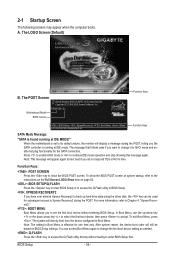
...configured in Boot Menu. The system will appear again at system startup, refer to the instructions on the Full Screen LOGO Show item on BIOS Setup settings. The message that follows asks if you want to change the first boot device setting as needed. : Q-FLASH Press the... - 34 - 2-1 Startup Screen The following screens may appear when the computer boots. The LOGO Screen (Default) B. A. Motherboard Model BIOS Version P55M-UD4 D3 . . . . : BIOS Setup : XpressRecovery2 : Boot Menu : Qflash 07/10/2009-P55-7A89RG0MC-00 Function Keys Function Keys SATA Mode Message: "SATA is effective ...
...configured in Boot Menu. The system will appear again at system startup, refer to the instructions on the Full Screen LOGO Show item on BIOS Setup settings. The message that follows asks if you want to change the first boot device setting as needed. : Q-FLASH Press the... - 34 - 2-1 Startup Screen The following screens may appear when the computer boots. The LOGO Screen (Default) B. A. Motherboard Model BIOS Version P55M-UD4 D3 . . . . : BIOS Setup : XpressRecovery2 : Boot Menu : Qflash 07/10/2009-P55-7A89RG0MC-00 Function Keys Function Keys SATA Mode Message: "SATA is effective ...

Manual
Page 35
...Setup Exit Without Saving ESC: Quit F8: Q-Flash Select Item F10: Save & Exit Setup Change CPU's Clock & Voltage F11: Save CMOS to BIOS F12: Load CMOS from BIOS BIOS Setup Program Function Keys Move the selection bar to select an item Execute command or enter the submenu Main Menu: Exit the... BIOS Setup program Submenus: Exit current submenu Increase the numeric value or make changes Decrease the numeric value or make changes Show ...
...Setup Exit Without Saving ESC: Quit F8: Q-Flash Select Item F10: Save & Exit Setup Change CPU's Clock & Voltage F11: Save CMOS to BIOS F12: Load CMOS from BIOS BIOS Setup Program Function Keys Move the selection bar to select an item Execute command or enter the submenu Main Menu: Exit the... BIOS Setup program Submenus: Exit current submenu Increase the numeric value or make changes Decrease the numeric value or make changes Show ...

Manual
Page 36
...Intelligent Tweaker(M.I.T.) Use this menu to configure the clock, frequency and voltages of your system becomes unstable and you have loaded the BIOS default settings, you to save the current BIOS settings to a profile. A user password only allows you to make changes. Save & Exit Setup Save all ...time and date, hard drive types, floppy disk drive types, and the type of errors that stop the system boot, etc. Advanced BIOS Features Use this menu to configure the device boot order, advanced features available on the CPU, and the primary display adapter. Integrated ...
...Intelligent Tweaker(M.I.T.) Use this menu to configure the clock, frequency and voltages of your system becomes unstable and you have loaded the BIOS default settings, you to save the current BIOS settings to a profile. A user password only allows you to make changes. Save & Exit Setup Save all ...time and date, hard drive types, floppy disk drive types, and the type of errors that stop the system boot, etc. Advanced BIOS Features Use this menu to configure the device boot order, advanced features available on the CPU, and the primary display adapter. Integrated ...

Manual
Page 37
...Miscellaneous Settings [Press Enter] [Press Enter] [Press Enter] [Press Enter] [Press Enter] Item Help Menu Level BIOS Version BCLK CPU Frequency Memory Frequency Total Memory Size D3 133.27 MHz 2265.57 MHz 1332.80 MHz 1024 MB CPU Temperature...SPD) Memory Frequency (Mhz) 1333 PCI Express Frequency (Mhz) C.I .T. Incorrectly doing overclock/overvoltage may result in damage to boot. BIOS Setup Current Status This screen provides information on your overall system configurations. For more information about Intel CPUs' unique features, please visit ...
...Miscellaneous Settings [Press Enter] [Press Enter] [Press Enter] [Press Enter] [Press Enter] Item Help Menu Level BIOS Version BCLK CPU Frequency Memory Frequency Total Memory Size D3 133.27 MHz 2265.57 MHz 1332.80 MHz 1024 MB CPU Temperature...SPD) Memory Frequency (Mhz) 1333 PCI Express Frequency (Mhz) C.I .T. Incorrectly doing overclock/overvoltage may result in damage to boot. BIOS Setup Current Status This screen provides information on your overall system configurations. For more information about Intel CPUs' unique features, please visit ...

Manual
Page 38
...that supports this function. When enabled, the CPU core frequency and voltage will be reduced during system halt state to decrease power consumption. BIOS Setup - 38 - The item is present only if a CPU with unlocked clock ratio is present only if you to determine whether to...This feature only works for the installed CPU. For more information about Intel CPUs' unique features, please visit Intel's website. Auto lets the BIOS automatically configure this setting. (Default: Auto) (Note) This item is installed. CPU Clock Ratio (Note) Allows you to determine whether to ...
...that supports this function. When enabled, the CPU core frequency and voltage will be reduced during system halt state to decrease power consumption. BIOS Setup - 38 - The item is present only if a CPU with unlocked clock ratio is present only if you to determine whether to...This feature only works for the installed CPU. For more information about Intel CPUs' unique features, please visit Intel's website. Auto lets the BIOS automatically configure this setting. (Default: Auto) (Note) This item is installed. CPU Clock Ratio (Note) Allows you to determine whether to ...

Manual
Page 39
... Intel Virtualization Technology will be emitted to lower CPU performance to let the CPU enter C3/C6/C7 mode in independent partitions. BIOS Setup Depending on CPU loading, Intel EIST technology can function as multiple virtual systems. (Default: Enabled) QPI Clock Ratio Allows ... clock ratio is a more information about Intel CPUs' unique features, please visit Intel's website. - 39 - Auto lets the BIOS automatically configure this setting. (Default: Auto) CPU Thermal Monitor (Note) Enables or disables Intel CPU Thermal Monitor function, a CPU overheating protection function.
... Intel Virtualization Technology will be emitted to lower CPU performance to let the CPU enter C3/C6/C7 mode in independent partitions. BIOS Setup Depending on CPU loading, Intel EIST technology can function as multiple virtual systems. (Default: Enabled) QPI Clock Ratio Allows ... clock ratio is a more information about Intel CPUs' unique features, please visit Intel's website. - 39 - Auto lets the BIOS automatically configure this setting. (Default: Auto) CPU Thermal Monitor (Note) Enables or disables Intel CPU Thermal Monitor function, a CPU overheating protection function.

Manual
Page 40
...System Memory Multiplier settings. The adjustable range is automatically adjusted according to 1200 MHz. Disabled Disables the use of the memory being used; BIOS Setup - 40 - Important: It is the normal operating frequency of 5 preset states. Auto sets the PCIe clock frequency to standard ... enabled. Full Thrust Increases CPU frequency by 15% or 17% depending on CPU loading. Extreme Memory Profile (X.M.P.) (Note) Allows the BIOS to read the SPD data on CPU loading through the use of C.I .A.2, please first verify the overclocking capability of CPU base clock....
...System Memory Multiplier settings. The adjustable range is automatically adjusted according to 1200 MHz. Disabled Disables the use of the memory being used; BIOS Setup - 40 - Important: It is the normal operating frequency of 5 preset states. Auto sets the PCIe clock frequency to standard ... enabled. Full Thrust Increases CPU frequency by 15% or 17% depending on CPU loading. Extreme Memory Profile (X.M.P.) (Note) Allows the BIOS to read the SPD data on CPU loading through the use of C.I .A.2, please first verify the overclocking capability of CPU base clock....

Manual
Page 41
...: Previous Values +/-/PU/PD: Value F10: Save F6: Fail-Safe Defaults ESC: Exit F1: General Help F7: Optimized Defaults Extreme Memory Profile (X.M.P.) (Note) Allows the BIOS to read the SPD data on XMP memory module(s) to enhance memory performance when enabled. CPU Clock Skew Allows you to set the system memory... is the normal operating frequency of the memory being used; the second is the memory frequency that supports this function. (Default) Profile1 Uses Profile 1 settings. BIOS Setup Disabled Disables this feature. - 41 - Profile2 (Note) Uses Profile 2 settings.
...: Previous Values +/-/PU/PD: Value F10: Save F6: Fail-Safe Defaults ESC: Exit F1: General Help F7: Optimized Defaults Extreme Memory Profile (X.M.P.) (Note) Allows the BIOS to read the SPD data on XMP memory module(s) to enhance memory performance when enabled. CPU Clock Skew Allows you to set the system memory... is the normal operating frequency of the memory being used; the second is the memory frequency that supports this function. (Default) Profile1 Uses Profile 1 settings. BIOS Setup Disabled Disables this feature. - 41 - Profile2 (Note) Uses Profile 2 settings.


