
Manual
Page 1
.... To automatically set up a RAID 0 array: Click Auto to individually install the X.H.D utility later. eXtreme Hard Drive (X.H.D) With GIGABYTE eXtreme Hard Drive (X.H.D)(Note 1), users can quickly configure a RAIDready system for RAID 0. You can go to the Application Software screen ...Manual to the biggest drive in the array. ) 1. For a RAID 0 array that before you run the X.H.D utility, back up all motherboard drivers, including the X.H.D utility. A. Or you have to automatically install all of your needs and hardware components. 3. B. Before installing the operating...
.... To automatically set up a RAID 0 array: Click Auto to individually install the X.H.D utility later. eXtreme Hard Drive (X.H.D) With GIGABYTE eXtreme Hard Drive (X.H.D)(Note 1), users can quickly configure a RAIDready system for RAID 0. You can go to the Application Software screen ...Manual to the biggest drive in the array. ) 1. For a RAID 0 array that before you run the X.H.D utility, back up all motherboard drivers, including the X.H.D utility. A. Or you have to automatically install all of your needs and hardware components. 3. B. Before installing the operating...

Manual
Page 4
.... 2.1. Click the Install button on the "Xpress Install" main menu to the Install New Utilities menu. Some motherboard driver disks include the Smart TPM utility in "Xpress Install." 2. Installing the Infineon TPM Driver Insert the GIGABYTE motherboard driver disk. "Xpress Install" will install all of the selected drivers, including the Infineon TPM driver...
.... 2.1. Click the Install button on the "Xpress Install" main menu to the Install New Utilities menu. Some motherboard driver disks include the Smart TPM utility in "Xpress Install." 2. Installing the Infineon TPM Driver Insert the GIGABYTE motherboard driver disk. "Xpress Install" will install all of the selected drivers, including the Infineon TPM driver...

Manual
Page 7
... appear. Then enter the same passkey on your cell phone for the Bluetooth enabled cell phone(s). Before creating a Bluetooth cell phone key, make sure your motherboard includes a Bluetooth receiver and turn on the search and Bluetooth functions on your phone. Selecting the Enable Backup to use as the portable Smart TPM...
... appear. Then enter the same passkey on your cell phone for the Bluetooth enabled cell phone(s). Before creating a Bluetooth cell phone key, make sure your motherboard includes a Bluetooth receiver and turn on the search and Bluetooth functions on your phone. Selecting the Enable Backup to use as the portable Smart TPM...

Manual
Page 19
...'t display your Bluetooth-enabled cell phone, click Refresh to let Smart TPM re-detect the device.) Before creating a Bluetooth cell phone key, make sure your motherboard includes a Bluetooth receiver and turn off or reset your computer when a USB key is being created. • If you want to confirm, click Yes. To...
...'t display your Bluetooth-enabled cell phone, click Refresh to let Smart TPM re-detect the device.) Before creating a Bluetooth cell phone key, make sure your motherboard includes a Bluetooth receiver and turn off or reset your computer when a USB key is being created. • If you want to confirm, click Yes. To...
Manual
Page 1
GA-P55A-UD3P GA-P55A-UD3R LGA1156 socket motherboard for Intel® Core™ i7 processor family/ Intel® Core™ i5 processor family User's Manual Rev. 1002 12ME-P55AU3P-1002R
GA-P55A-UD3P GA-P55A-UD3R LGA1156 socket motherboard for Intel® Core™ i7 processor family/ Intel® Core™ i5 processor family User's Manual Rev. 1002 12ME-P55AU3P-1002R
Manual
Page 2
Motherboard GA-P55A-UD3P/GA-P55A-UD3R Oct. 16, 2009 Motherboard GA-P55A-UD3P/ GA-P55A-UD3R Oct. 16, 2009
Motherboard GA-P55A-UD3P/GA-P55A-UD3R Oct. 16, 2009 Motherboard GA-P55A-UD3P/ GA-P55A-UD3R Oct. 16, 2009
Manual
Page 3
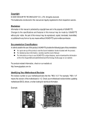
...carefully read or download the information on/from the Support&Downloads\Motherboard\Technology Guide page on our website. The trademarks mentioned in this manual are legally registered to assist in the use GIGABYTE's unique features, read the User's Manual. Example: Changes... CO., LTD. For instructions on your motherboard revision before updating motherboard BIOS, drivers, or when looking for technical information. For product-related information, check on our website at: http://www.gigabyte.com.tw Identifying Your Motherboard Revision The revision number on how to the...
...carefully read or download the information on/from the Support&Downloads\Motherboard\Technology Guide page on our website. The trademarks mentioned in this manual are legally registered to assist in the use GIGABYTE's unique features, read the User's Manual. Example: Changes... CO., LTD. For instructions on your motherboard revision before updating motherboard BIOS, drivers, or when looking for technical information. For product-related information, check on our website at: http://www.gigabyte.com.tw Identifying Your Motherboard Revision The revision number on how to the...
Manual
Page 4
Table of Contents Box Contents...6 Optional Items...6 GA-P55A-UD3P/GA-P55A-UD3R Motherboard Layout 7 Block Diagram...8 Chapter 1 Hardware Installation 9 1-1 Installation Precautions 9 1-2 Product Specifications 10 1-3 Installing the CPU and CPU Cooler 13 1-3-1 Installing the CPU 13 1-3-2 Installing the CPU ...
Table of Contents Box Contents...6 Optional Items...6 GA-P55A-UD3P/GA-P55A-UD3R Motherboard Layout 7 Block Diagram...8 Chapter 1 Hardware Installation 9 1-1 Installation Precautions 9 1-2 Product Specifications 10 1-3 Installing the CPU and CPU Cooler 13 1-3-1 Installing the CPU 13 1-3-2 Installing the CPU ...
Manual
Page 6
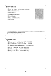
Box Contents GA-P55A-UD3P or GA-P55A-UD3R motherboard Motherboard driver disk User's Manual Quick Installation Guide One IDE cable Four SATA 3Gb/s cables I/O Shield • The box contents above are subject to change without notice. • The motherboard image is for reference only and the actual items shall depend on the product package you obtain. The box...
Box Contents GA-P55A-UD3P or GA-P55A-UD3R motherboard Motherboard driver disk User's Manual Quick Installation Guide One IDE cable Four SATA 3Gb/s cables I/O Shield • The box contents above are subject to change without notice. • The motherboard image is for reference only and the actual items shall depend on the product package you obtain. The box...
Manual
Page 7
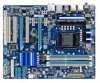
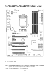
GA-P55A-UD3P/GA-P55A-UD3R Motherboard Layout KB_USB R_SPDIF CPU_FAN ATX_12V_2X4 USB_ESATA_2 USB_ESATA_1 LGA1156 PHASE LED ATX R_USB USB30_LAN NEC AUDIO F_AUDIO JMB362 GA-P55A-UD3P GA-P55A-UD3R PCIEX1_1 (Note 1) SYS_FAN1 RTL8111D PCIEX16 PCIEX1_2 BAT CODEC PCI1 CD_IN SPDIF_I SPDIF_O ...Intel® P55 SATA2_3 SATA2_0 SATA2_4 SATA2_1 SATA2_5 SATA2_2 PCI2 IDE IT8720 IT8213 PCI3 LPT COMA CLR_CMOS FDD F_USB2 F_USB1 F_PANEL j Only for GA-P55A-UD3P. (Note 1) Due to different regional policy. - 7 - For a longer expansion card, use other expansion slots. (Note 2) This...
GA-P55A-UD3P/GA-P55A-UD3R Motherboard Layout KB_USB R_SPDIF CPU_FAN ATX_12V_2X4 USB_ESATA_2 USB_ESATA_1 LGA1156 PHASE LED ATX R_USB USB30_LAN NEC AUDIO F_AUDIO JMB362 GA-P55A-UD3P GA-P55A-UD3R PCIEX1_1 (Note 1) SYS_FAN1 RTL8111D PCIEX16 PCIEX1_2 BAT CODEC PCI1 CD_IN SPDIF_I SPDIF_O ...Intel® P55 SATA2_3 SATA2_0 SATA2_4 SATA2_1 SATA2_5 SATA2_2 PCI2 IDE IT8720 IT8213 PCI3 LPT COMA CLR_CMOS FDD F_USB2 F_USB1 F_PANEL j Only for GA-P55A-UD3P. (Note 1) Due to different regional policy. - 7 - For a longer expansion card, use other expansion slots. (Note 2) This...
Manual
Page 9
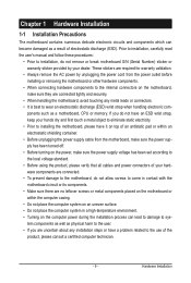
... using the product, please verify that all cables and power connectors of your hardware components are connected. • To prevent damage to the motherboard, do not have an ESD wrist strap, keep your dealer. Prior to installation, carefully read the user's manual and follow these procedures: ...• Prior to installation, do not remove or break motherboard S/N (Serial Number) sticker or warranty sticker provided by unplugging the power cord from the motherboard, make sure the power supply has been turned off. • Before turning on the power,...
... using the product, please verify that all cables and power connectors of your hardware components are connected. • To prevent damage to the motherboard, do not have an ESD wrist strap, keep your dealer. Prior to installation, carefully read the user's manual and follow these procedures: ...• Prior to installation, do not remove or break motherboard S/N (Serial Number) sticker or warranty sticker provided by unplugging the power cord from the motherboard, make sure the power supply has been turned off. • Before turning on the power,...
Manual
Page 12
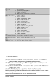
... Internet Security (OEM version) Operating System w Support for Microsoft® Windows® 7/Vista/XP Form Factor w ATX Form Factor; 30.5cm x 24.4cm j Only for GA-P55A-UD3P. (Note 1) Due to Windows Vista/XP 32-bit operating system limitation, when more than 4 GB of physical memory is installed, the actual memory size displayed... CPU/system fan speed control function is supported will depend on the CPU/system cooler you install. (Note 6) Available functions in EasyTune may differ by motherboard model. Hardware Installation - 12 -
... Internet Security (OEM version) Operating System w Support for Microsoft® Windows® 7/Vista/XP Form Factor w ATX Form Factor; 30.5cm x 24.4cm j Only for GA-P55A-UD3P. (Note 1) Due to Windows Vista/XP 32-bit operating system limitation, when more than 4 GB of physical memory is installed, the actual memory size displayed... CPU/system fan speed control function is supported will depend on the CPU/system cooler you install. (Note 6) Available functions in EasyTune may differ by motherboard model. Hardware Installation - 12 -
Manual
Page 13
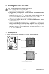
... bus frequency be inserted if oriented incorrectly. (Or you wish to set beyond the standard specifications, please do so according to GIGABYTE's website for the peripherals. The CPU cannot be set the frequency beyond hardware specifications since it does not meet the standard requirements... for the latest CPU support list.) • Always turn on the computer if the CPU cooler is not recommended that the motherboard supports the CPU. (Go to your hardware specifications including the CPU, graphics card, memory, hard drive, etc. 1-3-1 Installing the CPU A....
... bus frequency be inserted if oriented incorrectly. (Or you wish to set beyond the standard specifications, please do so according to GIGABYTE's website for the peripherals. The CPU cannot be set the frequency beyond hardware specifications since it does not meet the standard requirements... for the latest CPU support list.) • Always turn on the computer if the CPU cooler is not recommended that the motherboard supports the CPU. (Go to your hardware specifications including the CPU, graphics card, memory, hard drive, etc. 1-3-1 Installing the CPU A....
Manual
Page 14
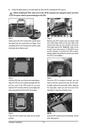
... as well. NOTE: Hold the CPU socket lever by the handle, not the lever base portion. Step 5: Push the CPU socket lever back into the motherboard CPU socket. Before installing the CPU, make sure the front end of the socket cover and use the other to the CPU. Align the CPU...
... as well. NOTE: Hold the CPU socket lever by the handle, not the lever base portion. Step 5: Push the CPU socket lever back into the motherboard CPU socket. Before installing the CPU, make sure the front end of the socket cover and use the other to the CPU. Align the CPU...
Manual
Page 15
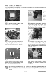
...removing the CPU cooler may adhere to the CPU. 1-3-2 Installing the CPU Cooler Follow the steps below to correctly install the CPU cooler on the motherboard. (The following procedure uses Intel® boxed cooler as the picture above shows, the installation is to install.) Step 3: Place the cooler ...atop the CPU, aligning the four push pins through the pin holes on installing the cooler.) Step 5: After the installation, check the back of the motherboard. Step 4: You should hear a "click" when pushing down on the surface of arrow is to remove the cooler, on the contrary, is complete....
...removing the CPU cooler may adhere to the CPU. 1-3-2 Installing the CPU Cooler Follow the steps below to correctly install the CPU cooler on the motherboard. (The following procedure uses Intel® boxed cooler as the picture above shows, the installation is to install.) Step 3: Place the cooler ...atop the CPU, aligning the four push pins through the pin holes on installing the cooler.) Step 5: After the installation, check the back of the motherboard. Step 4: You should hear a "click" when pushing down on the surface of arrow is to remove the cooler, on the contrary, is complete....
Manual
Page 16
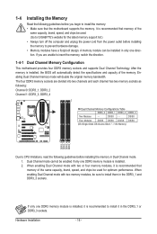
... with two memory modules, be installed in Dual Channel mode. 1. If you begin to install the memory: • Make sure that the motherboard supports the memory. Hardware Installation - 16 - After the memory is installed. 2. If only one DDR3 memory module is installed, it is ... memory mode will automatically detect the specifications and capacity of the same capacity, brand, speed, and chips be used . (Go to GIGABYTE's website for optimum performance. 1-4 Installing the Memory Read the following guidelines before you are divided into two channels and each channel has two...
... with two memory modules, be installed in Dual Channel mode. 1. If you begin to install the memory: • Make sure that the motherboard supports the memory. Hardware Installation - 16 - After the memory is installed. 2. If only one DDR3 memory module is installed, it is ... memory mode will automatically detect the specifications and capacity of the same capacity, brand, speed, and chips be used . (Go to GIGABYTE's website for optimum performance. 1-4 Installing the Memory Read the following guidelines before you are divided into two channels and each channel has two...

Manual
Page 17
..., make sure to turn off the computer and unplug the power cord from the power outlet to prevent damage to install DDR3 DIMMs on this motherboard. DDR3 and DDR2 DIMMs are not compatible to each other or DDR DIMMs. Be sure to the memory module.
..., make sure to turn off the computer and unplug the power cord from the power outlet to prevent damage to install DDR3 DIMMs on this motherboard. DDR3 and DDR2 DIMMs are not compatible to each other or DDR DIMMs. Be sure to the memory module.
Manual
Page 18
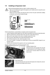
... is fully inserted into the slot. 4. Turn on the top edge of the PCI Express slot to install an expansion card: • Make sure the motherboard supports the expansion card. Remove the metal slot cover from the slot. Locate an expansion slot that came with a screw. 5. If necessary, go to BIOS...
... is fully inserted into the slot. 4. Turn on the top edge of the PCI Express slot to install an expansion card: • Make sure the motherboard supports the expansion card. Remove the metal slot cover from the slot. Locate an expansion slot that came with a screw. 5. If necessary, go to BIOS...

Manual
Page 19
.../Mouse Port Use this port for instructions on configuring a RAID array. Before using this feature, ensure that your device and then remove it from the motherboard. • When removing the cable, pull it side to side to a back panel connector, first remove the cable from the connector. eSATA 3Gb/s Port The...
.../Mouse Port Use this port for instructions on configuring a RAID array. Before using this feature, ensure that your device and then remove it from the motherboard. • When removing the cable, pull it side to side to a back panel connector, first remove the cable from the connector. eSATA 3Gb/s Port The...

Manual
Page 21
..., make sure your devices are compliant with the connectors you wish to connect. • Before installing the devices, be sure to the connector on the motherboard. - 21 -
..., make sure your devices are compliant with the connectors you wish to connect. • Before installing the devices, be sure to the connector on the motherboard. - 21 -


