Manual
Page 7
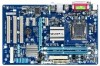
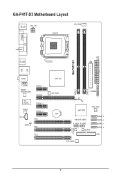
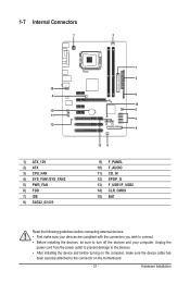
GA-P41T-D3 Motherboard Layout KB_MS ATX_12V LGA775 CPU_FAN COMA LPT LAN COAXIAL R_USB ATX IDE GA-P41T-D3 USB AUDIO F_AUDIO Realtek RTL8111C/D/E PCIEX1_1 PCIEX16 iTE IT8718 PCIEX1_2 CODEC CD_IN PCIEX1_3 PCI1 SPDIF_O PCI2 PCI3 Intel® G41 SYS_FAN1 F_PANEL DDR3_1 DDR3_2 Intel® ICH7 PWR_FAN BAT SATA2_3 CLR_CMOS SATA2_2 F_USB1 F_USB2 SATA2_1 B_BIOS SATA2_0 M_BIOS FDD SYS_FAN2 - 7 -
GA-P41T-D3 Motherboard Layout KB_MS ATX_12V LGA775 CPU_FAN COMA LPT LAN COAXIAL R_USB ATX IDE GA-P41T-D3 USB AUDIO F_AUDIO Realtek RTL8111C/D/E PCIEX1_1 PCIEX16 iTE IT8718 PCIEX1_2 CODEC CD_IN PCIEX1_3 PCI1 SPDIF_O PCI2 PCI3 Intel® G41 SYS_FAN1 F_PANEL DDR3_1 DDR3_2 Intel® ICH7 PWR_FAN BAT SATA2_3 CLR_CMOS SATA2_2 F_USB1 F_USB2 SATA2_1 B_BIOS SATA2_0 M_BIOS FDD SYS_FAN2 - 7 -
Manual
Page 11
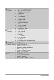
Hardware Installation Internal Connectors Back Panel Connectors w 1 x 24-pin ATX main power connector w 1 x 4-pin ATX 12V power connector w 1 x floppy disk drive connector w 1 x IDE connector w 4 x SATA 3Gb/s connectors w 1 x CPU fan header w 2 x system fan headers w 1 x power fan header w 1 x front panel header w 1 x front ...
Hardware Installation Internal Connectors Back Panel Connectors w 1 x 24-pin ATX main power connector w 1 x 4-pin ATX 12V power connector w 1 x floppy disk drive connector w 1 x IDE connector w 4 x SATA 3Gb/s connectors w 1 x CPU fan header w 2 x system fan headers w 1 x power fan header w 1 x front panel header w 1 x front ...
Manual
Page 12
... Support for ON/OFF Charge Support for Q-Share Norton Internet Security (OEM version) Operating System w Support for Microsoft® Windows® 7/Vista/XP Form Factor w ATX Form Factor; 30.5cm x 19.4cm (Note 1) Due to standard PC architecture, a certain amount of memory is reserved for system usage, the actual memory size...
... Support for ON/OFF Charge Support for Q-Share Norton Internet Security (OEM version) Operating System w Support for Microsoft® Windows® 7/Vista/XP Form Factor w ATX Form Factor; 30.5cm x 19.4cm (Note 1) Due to standard PC architecture, a certain amount of memory is reserved for system usage, the actual memory size...
Manual
Page 21
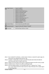
1-7 Internal Connectors 1 3 10 4 15 11 12 1) ATX_12V 2) ATX 3) CPU_FAN 4) SYS_FAN1/SYS_FAN2 5) PWR_FAN 6) FDD 7) IDE 8) SATA2_0/1/2/3 7 2 9 14 5 8 6 13 4 9) 10) 11) 12) 13) 14) 15) F_PANEL F_AUDIO CD_IN SPDIF_O F_USB1/F_USB2 CLR_CMOS BAT Read the ...
1-7 Internal Connectors 1 3 10 4 15 11 12 1) ATX_12V 2) ATX 3) CPU_FAN 4) SYS_FAN1/SYS_FAN2 5) PWR_FAN 6) FDD 7) IDE 8) SATA2_0/1/2/3 7 2 9 14 5 8 6 13 4 9) 10) 11) 12) 13) 14) 15) F_PANEL F_AUDIO CD_IN SPDIF_O F_USB1/F_USB2 CLR_CMOS BAT Read the ...
Manual
Page 22
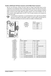
...required power, the result can lead to an unstable or unbootable system. 3 4 1 2 ATX_12V ATX_12V: Pin No. 1 2 3 4 Definition GND GND +12V +12V 12 24 1 13 ATX ATX: Pin No. 1 2 3 4 5 6 7 8 9 10 11 12 Definition Pin No. 3.3V 13 3.3V 14 GND 15 +5V 16 GND 17 +5V 18 GND 19 Power Good... computer will not start. If the 12V power connector is used (500W or greater). Connect the power supply cable to the CPU. 1/2) ATX_12V/ATX (2x2 12V Power Connector and 2x12 Main Power Connector) With the use of the power connector, the power supply can supply enough stable power to...
...required power, the result can lead to an unstable or unbootable system. 3 4 1 2 ATX_12V ATX_12V: Pin No. 1 2 3 4 Definition GND GND +12V +12V 12 24 1 13 ATX ATX: Pin No. 1 2 3 4 5 6 7 8 9 10 11 12 Definition Pin No. 3.3V 13 3.3V 14 GND 15 +5V 16 GND 17 +5V 18 GND 19 Power Good... computer will not start. If the 12V power connector is used (500W or greater). Connect the power supply cable to the CPU. 1/2) ATX_12V/ATX (2x2 12V Power Connector and 2x12 Main Power Connector) With the use of the power connector, the power supply can supply enough stable power to...
Manual
Page 48
... state exactly where it was left off the computer in MS-DOS mode using the power button. Note: To use this function, you need an ATX power supply providing at any time. S3(STR) Enables the system to enter the ACPI S3 (Suspend to enter the ACPI S1 (Power on Windows...
... state exactly where it was left off the computer in MS-DOS mode using the power button. Note: To use this function, you need an ATX power supply providing at any time. S3(STR) Enables the system to enter the ACPI S3 (Suspend to enter the ACPI S1 (Power on Windows...
Manual
Page 49
... the return of the AC power, or the settings may not be powered on the +5VSB lead. Select 32-bit mode when you need an ATX power supply providing at a desired time. (Default: Disabled) If enabled, set the date and time as following four functions will be effective. Power On By... Keyboard Allows the system to be turned on by a PS/2 mouse wake-up event. (Default: Disabled) Note: To use this function, you need an ATX power supply providing at a specific time on each day or on the system. Password Set a password with up to 5 characters and then press to turn...
... the return of the AC power, or the settings may not be powered on the +5VSB lead. Select 32-bit mode when you need an ATX power supply providing at a desired time. (Default: Disabled) If enabled, set the date and time as following four functions will be effective. Power On By... Keyboard Allows the system to be turned on by a PS/2 mouse wake-up event. (Default: Disabled) Note: To use this function, you need an ATX power supply providing at a specific time on each day or on the system. Password Set a password with up to 5 characters and then press to turn...
Manual
Page 79
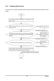
... is installed properly on the CPU. Connect the CPU cooler power cable to the CPU securely. Yes The problem is verified and solved. Connect the ATX main power cable and the 12V power cable. Remove all peripherals, connecting cables, and power cord etc. Secure the CPU cooler No on the memory...
... is installed properly on the CPU. Connect the CPU cooler power cable to the CPU securely. Yes The problem is verified and solved. Connect the ATX main power cable and the 12V power cable. Remove all peripherals, connecting cables, and power cord etc. Secure the CPU cooler No on the memory...
