Manual
Page 1
GA-P41-ES3G LGA775 socket motherboard for Intel® Core™ processor family/ Intel® Pentium® processor family/Intel® Celeron® processor family User's Manual Rev. 1001 12ME-P41ES3G-1001R
GA-P41-ES3G LGA775 socket motherboard for Intel® Core™ processor family/ Intel® Pentium® processor family/Intel® Celeron® processor family User's Manual Rev. 1001 12ME-P41ES3G-1001R
Manual
Page 2
Motherboard GA-P41-ES3G Sept. 21, 2009 Motherboard GA-P41-ES3G Sept. 21, 2009
Motherboard GA-P41-ES3G Sept. 21, 2009 Motherboard GA-P41-ES3G Sept. 21, 2009
Manual
Page 3
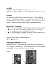
...TECHNOLOGY CO., LTD. The trademarks mentioned in the use GIGABYTE's unique features, read or download the information on/from the Support&Downloads\Motherboard\Technology Guide page on your motherboard revision before updating motherboard BIOS, drivers, or when looking for technical information. For...manual are legally registered to use of this : "REV: X.X." Check your motherboard looks like this product, GIGABYTE provides the following types of documentations: For quick set-up of GIGABYTE. For instructions on how to their respective owners. For product-related information,...
...TECHNOLOGY CO., LTD. The trademarks mentioned in the use GIGABYTE's unique features, read or download the information on/from the Support&Downloads\Motherboard\Technology Guide page on your motherboard revision before updating motherboard BIOS, drivers, or when looking for technical information. For...manual are legally registered to use of this : "REV: X.X." Check your motherboard looks like this product, GIGABYTE provides the following types of documentations: For quick set-up of GIGABYTE. For instructions on how to their respective owners. For product-related information,...
Manual
Page 4
Table of Contents Box Contents...6 Optional Items...6 GA-P41-ES3G Motherboard Layout 7 Block Diagram...8 Chapter 1 Hardware Installation 9 1-1 Installation Precautions 9 1-2 Product Specifications 10 1-3 Installing the CPU and CPU Cooler 13 1-3-1 Installing the CPU 13 1-3-2 Installing the CPU ...
Table of Contents Box Contents...6 Optional Items...6 GA-P41-ES3G Motherboard Layout 7 Block Diagram...8 Chapter 1 Hardware Installation 9 1-1 Installation Precautions 9 1-2 Product Specifications 10 1-3 Installing the CPU and CPU Cooler 13 1-3-1 Installing the CPU 13 1-3-2 Installing the CPU ...
Manual
Page 6
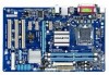
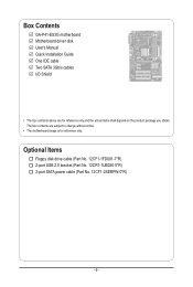
The box contents are for reference only. Optional Items Floppy disk drive cable (Part No. 12CF1-1FD001-7*R) 2-port USB 2.0 bracket (Part No. 12CR1-1UB030-5*R) 2-port SATA power cable (Part No. 12CF1-2SERPW-0*R) - 6 - Box Contents GA-P41-ES3G motherboard Motherboard driver disk User's Manual Quick Installation Guide One IDE cable Two SATA 3Gb/s cables I/O Shield • The box contents above are subject to change without notice. • The motherboard image is for reference only and the actual items shall depend on the product package you obtain.
The box contents are for reference only. Optional Items Floppy disk drive cable (Part No. 12CF1-1FD001-7*R) 2-port USB 2.0 bracket (Part No. 12CR1-1UB030-5*R) 2-port SATA power cable (Part No. 12CF1-2SERPW-0*R) - 6 - Box Contents GA-P41-ES3G motherboard Motherboard driver disk User's Manual Quick Installation Guide One IDE cable Two SATA 3Gb/s cables I/O Shield • The box contents above are subject to change without notice. • The motherboard image is for reference only and the actual items shall depend on the product package you obtain.
Manual
Page 9
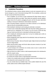
...such as a result of the product, please consult a certified computer technician. - 9 - Chapter 1 Hardware Installation 1-1 Installation Precautions The motherboard contains numerous delicate electronic circuits and components which can lead to damage to system components as well as physical harm to the user. &#... strap, keep your hands dry and first touch a metal object to eliminate static electricity. • Prior to installing the motherboard, please have a problem related to the use of electrostatic discharge (ESD). Hardware Installation Prior to installation, carefully read the user...
...such as a result of the product, please consult a certified computer technician. - 9 - Chapter 1 Hardware Installation 1-1 Installation Precautions The motherboard contains numerous delicate electronic circuits and components which can lead to damage to system components as well as physical harm to the user. &#... strap, keep your hands dry and first touch a metal object to eliminate static electricity. • Prior to installing the motherboard, please have a problem related to the use of electrostatic discharge (ESD). Hardware Installation Prior to installation, carefully read the user...
Manual
Page 12
... Form Factor w ATX Form Factor; 30.5cm x 19.4cm (Note 1) Based on the CPU cooler you install. (Note 4) Available functions in EasyTune may differ by motherboard model. (Note 5) Due to the hardware limitation, you have to enable support for system usage and therefore the actual memory size is supported will depend...
... Form Factor w ATX Form Factor; 30.5cm x 19.4cm (Note 1) Based on the CPU cooler you install. (Note 4) Available functions in EasyTune may differ by motherboard model. (Note 5) Due to the hardware limitation, you have to enable support for system usage and therefore the actual memory size is supported will depend...
Manual
Page 13
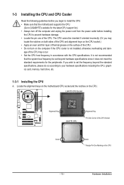
...for the latest CPU support list.) • Always turn on the computer if the CPU cooler is not recommended that the motherboard supports the CPU. (Go to GIGABYTE's website for the peripherals. age of the CPU may locate the notches on both sides of the CPU and alignment keys...Notch Triangle Pin One Marking on the CPU. It is not installed, otherwise overheating and dam- Hardware Installation Locate the alignment keys on the motherboard CPU socket and the notches on the CPU - 13 - 1-3 Installing the CPU and CPU Cooler Read the following guidelines before installing the CPU...
...for the latest CPU support list.) • Always turn on the computer if the CPU cooler is not recommended that the motherboard supports the CPU. (Go to GIGABYTE's website for the peripherals. age of the CPU may locate the notches on both sides of the CPU and alignment keys...Notch Triangle Pin One Marking on the CPU. It is not installed, otherwise overheating and dam- Hardware Installation Locate the alignment keys on the motherboard CPU socket and the notches on the CPU - 13 - 1-3 Installing the CPU and CPU Cooler Read the following guidelines before installing the CPU...
Manual
Page 14
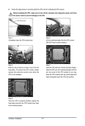
.... (DO NOT touch socket contacts.) Step 3: Remove the protective socket cover from the power outlet to prevent damage to correctly install the CPU into the motherboard CPU socket. B.
.... (DO NOT touch socket contacts.) Step 3: Remove the protective socket cover from the power outlet to prevent damage to correctly install the CPU into the motherboard CPU socket. B.
Manual
Page 15
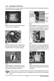
...for instructions on installing the cooler.) Step 5: After the installation, check the back of the CPU cooler to the CPU fan header (CPU_FAN) on the motherboard. Use extreme care when removing the CPU cooler because the thermal grease/tape between the CPU cooler and CPU may damage the CPU. - 15 - Step...above shows, the installation is to install.) Step 3: Place the cooler atop the CPU, aligning the four push pins through the pin holes on the motherboard. Direction of the Arrow Sign on the Male Push Pin Male Push Pin The Top of Female Push Pin Female Push Pin Step 2: Before installing...
...for instructions on installing the cooler.) Step 5: After the installation, check the back of the CPU cooler to the CPU fan header (CPU_FAN) on the motherboard. Use extreme care when removing the CPU cooler because the thermal grease/tape between the CPU cooler and CPU may damage the CPU. - 15 - Step...above shows, the installation is to install.) Step 3: Place the cooler atop the CPU, aligning the four push pins through the pin holes on the motherboard. Direction of the Arrow Sign on the Male Push Pin Male Push Pin The Top of Female Push Pin Female Push Pin Step 2: Before installing...
Manual
Page 16
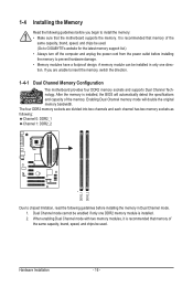
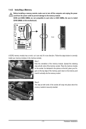
... used . (Go to GIGABYTE's website for the latest memory support list.) • Always turn off the computer and unplug the power cord from the power outlet before installing the memory in only one DDR2 memory module is recommended that the motherboard supports the memory. If ...a foolproof design. The four DDR2 memory sockets are unable to insert the memory, switch the direction. 1-4-1 Dual Channel Memory Configuration This motherboard provides four DDR2 memory sockets and supports Dual Channel Technology. It is installed, the BIOS will double the original memory bandwidth. Dual Channel...
... used . (Go to GIGABYTE's website for the latest memory support list.) • Always turn off the computer and unplug the power cord from the power outlet before installing the memory in only one DDR2 memory module is recommended that the motherboard supports the memory. If ...a foolproof design. The four DDR2 memory sockets are unable to insert the memory, switch the direction. 1-4-1 Dual Channel Memory Configuration This motherboard provides four DDR2 memory sockets and supports Dual Channel Technology. It is installed, the BIOS will double the original memory bandwidth. Dual Channel...
Manual
Page 17
... damage to correctly install your fingers on the top edge of the socket will snap into the memory socket. Place the memory module on this motherboard. As indicated in the picture on the left, place your memory modules in one direction. Spread the retaining clips at both ends of the memory...
... damage to correctly install your fingers on the top edge of the socket will snap into the memory socket. Place the memory module on this motherboard. As indicated in the picture on the left, place your memory modules in one direction. Spread the retaining clips at both ends of the memory...
Manual
Page 18
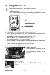
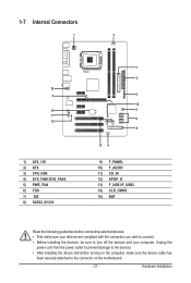
... Installation - 18 - PCI Express x1 Slot PCI Express x16 Slot PCI Slot Follow the steps below to install an expansion card: • Make sure the motherboard supports the expansion card. Install the driver provided with a screw. 5. Example: Installing and Removing a PCI Express Graphics Card: • Installing a Graphics Card: Gently push down...
... Installation - 18 - PCI Express x1 Slot PCI Express x16 Slot PCI Slot Follow the steps below to install an expansion card: • Make sure the motherboard supports the expansion card. Install the driver provided with a screw. 5. Example: Installing and Removing a PCI Express Graphics Card: • Installing a Graphics Card: Gently push down...
Manual
Page 19
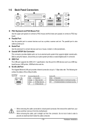
... electrical short inside the cable connector. - 19 - Parallel Port Use the parallel port to 1 Gbps data rate. Do not rock it straight out from the motherboard. • When removing the cable, pull it side to side to an external audio system that your device and then remove it from the connector...
... electrical short inside the cable connector. - 19 - Parallel Port Use the parallel port to 1 Gbps data rate. Do not rock it straight out from the motherboard. • When removing the cable, pull it side to side to an external audio system that your device and then remove it from the connector...
Manual
Page 21
..., make sure your devices are compliant with the connectors you wish to connect. • Before installing the devices, be sure to the connector on the motherboard. - 21 -
..., make sure your devices are compliant with the connectors you wish to connect. • Before installing the devices, be sure to the connector on the motherboard. - 21 -
Manual
Page 22
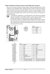
... power connector mainly supplies power to the power connector in the correct orientation. If a power supply is turned off and all the components on the motherboard. When using a 2x10 power supply. 3 4 1 2 ATX_12V ATX_12V: Pin No. 1 2 3 4 Definition GND GND +12V +12V 12 24 1 13 ATX ATX: Pin No. 1 2 3 4...under the protective cover when using a 2x12 power supply, remove the protective cover from the main power connector on the motherboard. Before connecting the power connector, first make sure the power supply is used that can withstand high power consumption be used ...
... power connector mainly supplies power to the power connector in the correct orientation. If a power supply is turned off and all the components on the motherboard. When using a 2x10 power supply. 3 4 1 2 ATX_12V ATX_12V: Pin No. 1 2 3 4 Definition GND GND +12V +12V 12 24 1 13 ATX ATX: Pin No. 1 2 3 4...under the protective cover when using a 2x12 power supply, remove the protective cover from the main power connector on the motherboard. Before connecting the power connector, first make sure the power supply is used that can withstand high power consumption be used ...
Manual
Page 23
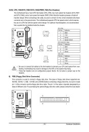
... fan be installed inside the chassis. 1 CPU_FAN 1 1 SYS_FAN1 SYS_FAN2 1 PWR_FAN CPU_FAN: Pin No. The types of different color. The motherboard supports CPU fan speed control, which requires the use of the cable is the ground wire). For optimum heat dissipation, it in damage to... are not configuration jumper blocks. The pin 1 of a CPU fan with fan speed control design. 3/4/5) CPU_FAN/SYS_FAN1/SYS_FAN2/PWR_FAN (Fan Headers) The motherboard has a 4-pin CPU fan header (CPU_FAN), two 3-pin system fan headers (SYS_FAN1 and SYS_FAN2), and a 3-pin power fan header (PWR_FAN). Most...
... fan be installed inside the chassis. 1 CPU_FAN 1 1 SYS_FAN1 SYS_FAN2 1 PWR_FAN CPU_FAN: Pin No. The types of different color. The motherboard supports CPU fan speed control, which requires the use of the cable is the ground wire). For optimum heat dissipation, it in damage to... are not configuration jumper blocks. The pin 1 of a CPU fan with fan speed control design. 3/4/5) CPU_FAN/SYS_FAN1/SYS_FAN2/PWR_FAN (Fan Headers) The motherboard has a 4-pin CPU fan header (CPU_FAN), two 3-pin system fan headers (SYS_FAN1 and SYS_FAN2), and a 3-pin power fan header (PWR_FAN). Most...
Manual
Page 26
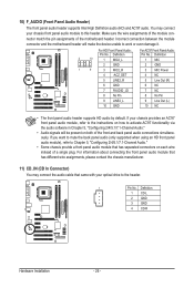
... module that came with your optical drive to the header. 1 Pin No. Incorrect connection between the module connector and the motherboard header will be present on each wire instead of the motherboard header. Definition Pin No. If your chassis front panel audio module to work or even damage it. For information about...
... module that came with your optical drive to the header. 1 Pin No. Incorrect connection between the module connector and the motherboard header will be present on each wire instead of the motherboard header. Definition Pin No. If your chassis front panel audio module to work or even damage it. For information about...
Manual
Page 27
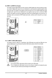
... display at the same time. For example, some graphics cards may require you to use a S/PDIF digital audio cable for digital audio output from your motherboard to your motherboard to USB 2.0/1.1 specification.
... display at the same time. For example, some graphics cards may require you to use a S/PDIF digital audio cable for digital audio output from your motherboard to your motherboard to USB 2.0/1.1 specification.
Manual
Page 28
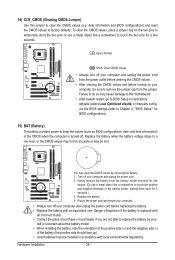
Failure to do so may cause damage to the motherboard. • After system restart, go to BIOS Setup to load factory defaults (select Load Optimized efaults) or manually configure the BIOS settings (refer to Chapter 2, "...
Failure to do so may cause damage to the motherboard. • After system restart, go to BIOS Setup to load factory defaults (select Load Optimized efaults) or manually configure the BIOS settings (refer to Chapter 2, "...


