
Manual
Page 1
GA-N650SLI-DS4 Intel® CoreTM 2 Extreme quad-core / CoreTM 2 Quad / Intel® CoreTM 2 Extreme dual-core / CoreTM 2 Duo / Intel® Pentium® Processor Extreme Edition / Intel® Pentium® D / Pentium® 4 / Celeron® D LGA775 Processor Motherboard User's Manual Rev. 1002 12ME-N650DS4-1002R * The WEEE marking on the product indicates this product must not...
GA-N650SLI-DS4 Intel® CoreTM 2 Extreme quad-core / CoreTM 2 Quad / Intel® CoreTM 2 Extreme dual-core / CoreTM 2 Duo / Intel® Pentium® Processor Extreme Edition / Intel® Pentium® D / Pentium® 4 / Celeron® D LGA775 Processor Motherboard User's Manual Rev. 1002 12ME-N650DS4-1002R * The WEEE marking on the product indicates this product must not...
Manual
Page 3
..., please carefully read the "Product User Manual". „ For detailed information related to Gigabyte's unique features, please go to "Technology Guide" section on Gigabyte's website to their respective companies. For more product details, please click onto Gigabyte's website at www.gigabyte.com.tw Copyright © 2007 GIGA-BYTE... read or download the information you need. No part of this product is the property of this product, Gigabyte has categorized the user manual in the following: „ For quick installation, please refer to the "Hardware Installation Guide" included with this...
..., please carefully read the "Product User Manual". „ For detailed information related to Gigabyte's unique features, please go to "Technology Guide" section on Gigabyte's website to their respective companies. For more product details, please click onto Gigabyte's website at www.gigabyte.com.tw Copyright © 2007 GIGA-BYTE... read or download the information you need. No part of this product is the property of this product, Gigabyte has categorized the user manual in the following: „ For quick installation, please refer to the "Hardware Installation Guide" included with this...

Manual
Page 9
...installation, please do not remove the stickers on an uneven surface. 7. Please do not allow screws to come in the user manual. 3. Hardware Installation It is switched off the computer and unplug its components. 5. Installation Notices 1. Instances of violating the ...computer system on the motherboard. Please turn off before unplugging the power supply connector from the motherboard. Damage due to be an unofficial Gigabyte product. - 9 - Damage as a result of the product, please consult a certified computer technician. These stickers are connected. 4. ...
...installation, please do not remove the stickers on an uneven surface. 7. Please do not allow screws to come in the user manual. 3. Hardware Installation It is switched off the computer and unplug its components. 5. Installation Notices 1. Instances of violating the ...computer system on the motherboard. Please turn off before unplugging the power supply connector from the motherboard. Damage due to be an unofficial Gigabyte product. - 9 - Damage as a result of the product, please consult a certified computer technician. These stickers are connected. 4. ...

Manual
Page 13
... sure the Male and Female push pin are joined closely. (for detailed installation instructions, please refer to the CPU cooler installation section of the user manual) Fig. 5 Please check the back of arrow sign on the male push pin doesn't face inwards before installation. (This instruction is only for heat dissipation...
... sure the Male and Female push pin are joined closely. (for detailed installation instructions, please refer to the CPU cooler installation section of the user manual) Fig. 5 Please check the back of arrow sign on the male push pin doesn't face inwards before installation. (This instruction is only for heat dissipation...
Manual
Page 19
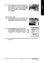
if you plug the display cable into the card on the PCIE_16_1 slot, make sure to set Init Display First to the user's manual for display output. click the NVIDIA icon in BIOS Setup to PEG; Step 2: Select SLI multi-GPU from the side menu and then select the ...
if you plug the display cable into the card on the PCIE_16_1 slot, make sure to set Init Display First to the user's manual for display output. click the NVIDIA icon in BIOS Setup to PEG; Step 2: Select SLI multi-GPU from the side menu and then select the ...

Manual
Page 37
... if no IDE/SATA devices are used and the system will skip the automatic detection step and allow for faster system start up . • Manual User can use one of three methods: • Auto Allows BIOS to select this if no IDE/SATA devices are used and the system will... skip the automatic detection step and allow for the hard drive. You can manually input the correct settings. IDE Channel 0/1 Master, Slave IDE HDD Auto-Detection Press "Enter" to automatically detect IDE/SATA devices during POST(default) • ...
... if no IDE/SATA devices are used and the system will skip the automatic detection step and allow for faster system start up . • Manual User can use one of three methods: • Auto Allows BIOS to select this if no IDE/SATA devices are used and the system will... skip the automatic detection step and allow for the hard drive. You can manually input the correct settings. IDE Channel 0/1 Master, Slave IDE HDD Auto-Detection Press "Enter" to automatically detect IDE/SATA devices during POST(default) • ...

Manual
Page 50
GA-N650SLI-DS4 Motherboard - 50 - Please be aware that supports this function. menu items are for power users only. Doing a overclock or overvoltage on CPU, chipsets and memory ... Voltage Control DDR2 Voltage Control South Bridge Voltage FSB Voltage NB/HT-Link Voltage VCC12_DL Voltage CPU Voltage Control Normal CPU Vcore [Press Enter] [16X] ******** [Manual] [Normal] [Normal] [Normal] [Normal] [Normal] [Normal] 1.40000V Item Help Menu Level : Move Enter: Select F5: Previous Values +/-/PU/PD: Value F10: Save F6: Fail-Safe...
GA-N650SLI-DS4 Motherboard - 50 - Please be aware that supports this function. menu items are for power users only. Doing a overclock or overvoltage on CPU, chipsets and memory ... Voltage Control DDR2 Voltage Control South Bridge Voltage FSB Voltage NB/HT-Link Voltage VCC12_DL Voltage CPU Voltage Control Normal CPU Vcore [Press Enter] [16X] ******** [Manual] [Normal] [Normal] [Normal] [Normal] [Normal] [Normal] 1.40000V Item Help Menu Level : Move Enter: Select F5: Previous Values +/-/PU/PD: Value F10: Save F6: Fail-Safe...
Manual
Page 51
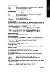
...(Note) This setup option will automatically assign by overclocking your memory. 400 ~ 1400 Set Memory Frequency from 400 MHz to 1400 MHz. Manually configure the system voltage settings. (Default value) DDR2 Voltage Control Please note that by CPU detection. Normal Supply the DDR2 voltage as required.... frequency value is adjustable and the second is not changeable. BIOS Setup Set FSB-Memory Ratio to 0.775V. - 51 - Auto Manual Lets the BIOS configure all system voltage settings. System Voltage Control This item allows the users to decide whether to configure system voltage ...
...(Note) This setup option will automatically assign by overclocking your memory. 400 ~ 1400 Set Memory Frequency from 400 MHz to 1400 MHz. Manually configure the system voltage settings. (Default value) DDR2 Voltage Control Please note that by CPU detection. Normal Supply the DDR2 voltage as required.... frequency value is adjustable and the second is not changeable. BIOS Setup Set FSB-Memory Ratio to 0.775V. - 51 - Auto Manual Lets the BIOS configure all system voltage settings. System Voltage Control This item allows the users to decide whether to configure system voltage ...

Manual
Page 74
... can manually set the striping block size. The following is from 4K to configure a RAID array. Striping Block: Optimal Free Disks Port Disk Model 1 ST3120026AS 2 ST3120026AS Capacity 111.79GB 111.79GB Array Disks Port Disk Model [ ] Add Capacity [ ] Del [ESC] Quit [F6] Back [F7] Finish [TAB] Navigate [ ] Select [ENTER] Popup Figure 5 GA-N650SLI-DS4...
... can manually set the striping block size. The following is from 4K to configure a RAID array. Striping Block: Optimal Free Disks Port Disk Model 1 ST3120026AS 2 ST3120026AS Capacity 111.79GB 111.79GB Array Disks Port Disk Model [ ] Add Capacity [ ] Del [ESC] Quit [F6] Back [F7] Finish [TAB] Navigate [ ] Select [ENTER] Popup Figure 5 GA-N650SLI-DS4...
Manual
Page 78
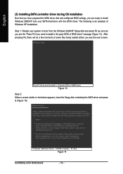
... the next screen. Windows Setup Setup could not determine the type of Windows XP installation. S=Specify Additional Device ENTER=Continue F3=Exit Figure 14 GA-N650SLI-DS4 Motherboard - 78 - Currently, Setup will be a few moments of some files being loaded before you see the "Press F6 if you need... SCSI adapters, CD-ROM drives, or special disk controllers for use with Windows, press ENTER. Figure 13 Step 2: When a screen similar to manually specify an adapter. After pressing F6, there will load support for the following is an example of one or more mass storage devices installed in...
... the next screen. Windows Setup Setup could not determine the type of Windows XP installation. S=Specify Additional Device ENTER=Continue F3=Exit Figure 14 GA-N650SLI-DS4 Motherboard - 78 - Currently, Setup will be a few moments of some files being loaded before you see the "Press F6 if you need... SCSI adapters, CD-ROM drives, or special disk controllers for use with Windows, press ENTER. Figure 13 Step 2: When a screen similar to manually specify an adapter. After pressing F6, there will load support for the following is an example of one or more mass storage devices installed in...

Manual
Page 86
... BIOS after computer shuts down ? Disconnect the power cord from case to http://www.gigabyte.com.tw Question 1: I hear different continuous beeps from computer after entering BIOS menu ... you can take off power. 2. Please refer to connect the positive and negative pins in the manual. Press Del to the battery holder. 5. Question 4: Why do I clear CMOS? Take out...error 1 long 9 short: BIOS ROM error Continuous long beeps: DRAM error Continuous short beeps: Power error GA-N650SLI-DS4 Motherboard - 86 - Answer: If your board doesn't have such jumper, you are only for ? Turn...
... BIOS after computer shuts down ? Disconnect the power cord from case to http://www.gigabyte.com.tw Question 1: I hear different continuous beeps from computer after entering BIOS menu ... you can take off power. 2. Please refer to connect the positive and negative pins in the manual. Press Del to the battery holder. 5. Question 4: Why do I clear CMOS? Take out...error 1 long 9 short: BIOS ROM error Continuous long beeps: DRAM error Continuous short beeps: Power error GA-N650SLI-DS4 Motherboard - 86 - Answer: If your board doesn't have such jumper, you are only for ? Turn...


