Manual
Page 3
...this manual may be reproduced, copied, translated, transmitted, or published in this : "REV: X.X." Example: Disclaimer Information in the use GIGABYTE's unique features, read the User's Manual. Documentation Classifications In order to their respective owners. For example, "REV: 1.0" means the...\Technology Guide page on your motherboard revision before updating motherboard BIOS, drivers, or when looking for technical information. For product-related information, check on our website at: http://www.gigabyte.com.tw Identifying Your Motherboard Revision The revision number on ...
...this manual may be reproduced, copied, translated, transmitted, or published in this : "REV: X.X." Example: Disclaimer Information in the use GIGABYTE's unique features, read the User's Manual. Documentation Classifications In order to their respective owners. For example, "REV: 1.0" means the...\Technology Guide page on your motherboard revision before updating motherboard BIOS, drivers, or when looking for technical information. For product-related information, check on our website at: http://www.gigabyte.com.tw Identifying Your Motherboard Revision The revision number on ...
Manual
Page 4
Table of Contents Box Contents...6 Optional Items...6 GA-MA785GPMT-UD2H/GA-MA785GMT-UD2H(US2H 7 Motherboard Layout...7 Block Diagram...8 Chapter 1 Hardware Installation 9 1-1 Installation Precautions 9 1-2 Product Specifications 10 1-3 Installing the CPU and...8482; Configuration 19 1-7 Back Panel Connectors 20 1-8 Internal Connectors 23 Chapter 2 BIOS Setup 35 2-1 Startup Screen 36 2-2 The Main Menu 37 2-3 MB Intelligent Tweaker(M.I.T 39 2-4 Standard CMOS Features 45 2-5 Advanced BIOS Features 47 2-6 Integrated Peripherals 50 2-7 Power Management Setup 53 2-8 PnP/PCI ...
Table of Contents Box Contents...6 Optional Items...6 GA-MA785GPMT-UD2H/GA-MA785GMT-UD2H(US2H 7 Motherboard Layout...7 Block Diagram...8 Chapter 1 Hardware Installation 9 1-1 Installation Precautions 9 1-2 Product Specifications 10 1-3 Installing the CPU and...8482; Configuration 19 1-7 Back Panel Connectors 20 1-8 Internal Connectors 23 Chapter 2 BIOS Setup 35 2-1 Startup Screen 36 2-2 The Main Menu 37 2-3 MB Intelligent Tweaker(M.I.T 39 2-4 Standard CMOS Features 45 2-5 Advanced BIOS Features 47 2-6 Integrated Peripherals 50 2-7 Power Management Setup 53 2-8 PnP/PCI ...
Manual
Page 5
...Manuals 62 3-4 Contact...63 3-5 System...63 3-6 Download Center 64 Chapter 4 Unique Features 65 4-1 Xpress Recovery2 65 4-2 BIOS Update Utilities 68 4-2-1 Updating the BIOS with the Q-Flash Utility 68 4-2-2 Updating the BIOS with the @BIOS Utility 71 4-3 EasyTune 6...72 4-4 Easy Energy Saver 73 4-5 Q-Share...75 4-6 Time Repair...76 Chapter 5 Appendix...... 5-2-5 Using the Sound Recorder 95 5-3 Troubleshooting 96 5-3-1 Frequently Asked Questions 96 5-3-2 Troubleshooting Procedure 97 5-4 Regulatory Statements 99 j Only for GA-MA785GMT-UD2H. - 5 - k Only for GA-MA785GPMT-UD2H.
...Manuals 62 3-4 Contact...63 3-5 System...63 3-6 Download Center 64 Chapter 4 Unique Features 65 4-1 Xpress Recovery2 65 4-2 BIOS Update Utilities 68 4-2-1 Updating the BIOS with the Q-Flash Utility 68 4-2-2 Updating the BIOS with the @BIOS Utility 71 4-3 EasyTune 6...72 4-4 Easy Energy Saver 73 4-5 Q-Share...75 4-6 Time Repair...76 Chapter 5 Appendix...... 5-2-5 Using the Sound Recorder 95 5-3 Troubleshooting 96 5-3-1 Frequently Asked Questions 96 5-3-2 Troubleshooting Procedure 97 5-4 Regulatory Statements 99 j Only for GA-MA785GMT-UD2H. - 5 - k Only for GA-MA785GPMT-UD2H.

Manual
Page 8
... Express x16 Dual Channel Memory Hyper Transport 3.0 PCI Express x16 PCI Express Bus x1 PCIe CLK (100 MHz) 1 PCI Express x1 RTL8111C RJ45 LAN Dual BIOS PCI Bus TSB43AB23 2 IEEE 1394a AMD 785G GFX CLK (100 MHz) D-Sub DVI-D or HDMI (Note) DDR3 SidePort Memoryj 12 USB Ports AMD SB710 ATA... Speaker Out Center/Subwoofer Speaker Out Side Speaker Out MIC Line Out Line In S/PDIF In S/ PDIF Out 2 PCI PCI CLK (33 MHz) j Only for GA-MA785GPMT-UD2H. (Note) Simultaneous output for DVI-D and HDMI is not supported. - 8 -
... Express x16 Dual Channel Memory Hyper Transport 3.0 PCI Express x16 PCI Express Bus x1 PCIe CLK (100 MHz) 1 PCI Express x1 RTL8111C RJ45 LAN Dual BIOS PCI Bus TSB43AB23 2 IEEE 1394a AMD 785G GFX CLK (100 MHz) D-Sub DVI-D or HDMI (Note) DDR3 SidePort Memoryj 12 USB Ports AMD SB710 ATA... Speaker Out Center/Subwoofer Speaker Out Side Speaker Out MIC Line Out Line In S/PDIF In S/ PDIF Out 2 PCI PCI CLK (33 MHz) j Only for GA-MA785GPMT-UD2H. (Note) Simultaneous output for DVI-D and HDMI is not supported. - 8 -
Manual
Page 12
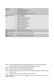
... w w w w w w w w w w Bundled Software w 2 x 8 Mbit flash Use of licensed AWARD BIOS Support for DualBIOS™ PnP 1.0a, DMI 2.0, SM BIOS 2.4, ACPI 1.0b Support for @BIOS Support for Q-Flash Support for Xpress BIOS Rescue Support for Download Center Support for Xpress Install Support for Xpress Recovery2 Support for EasyTune (Note 5) Support for Easy Energy Saver Support for...
... w w w w w w w w w w Bundled Software w 2 x 8 Mbit flash Use of licensed AWARD BIOS Support for DualBIOS™ PnP 1.0a, DMI 2.0, SM BIOS 2.4, ACPI 1.0b Support for @BIOS Support for Q-Flash Support for Xpress BIOS Rescue Support for Download Center Support for Xpress Install Support for Xpress Recovery2 Support for EasyTune (Note 5) Support for Easy Energy Saver Support for...
Manual
Page 16
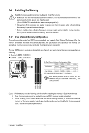
A memory module can be used . (Go to GIGABYTE's website for optimum performance. After the memory is installed, the BIOS will double the original memory bandwidth. Hardware Installation - 16 - The four DDR3 memory sockets are to be installed, it is recommended that memory of the ...
A memory module can be used . (Go to GIGABYTE's website for optimum performance. After the memory is installed, the BIOS will double the original memory bandwidth. Hardware Installation - 16 - The four DDR3 memory sockets are to be installed, it is recommended that memory of the ...
Manual
Page 18
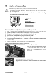
...the slot, and press down on the card are completely inserted into the PCI Express slot. Secure the card's metal bracket to make any required BIOS changes for your expansion card(s). 7. Install the driver provided with a screw. 5. PCI Express x1 Slot PCI Express x16 Slot PCI Slot Follow... slot. 1. 1-5 Installing an Expansion Card Read the following guidelines before installing an expansion card to prevent hardware damage. If necessary, go to BIOS Setup to the chassis back panel with the expansion card in the slot and does not rock. • Removing the Card from the chassis ...
...the slot, and press down on the card are completely inserted into the PCI Express slot. Secure the card's metal bracket to make any required BIOS changes for your expansion card(s). 7. Install the driver provided with a screw. 5. PCI Express x1 Slot PCI Express x16 Slot PCI Slot Follow... slot. 1. 1-5 Installing an Expansion Card Read the following guidelines before installing an expansion card to prevent hardware damage. If necessary, go to BIOS Setup to the chassis back panel with the expansion card in the slot and does not rock. • Removing the Card from the chassis ...
Manual
Page 19
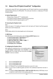
... significantly advanced display performance for GA-MA785GPMT-UD2H. An ATI Hybrid CrossFireX-supported motherboard and correct driver - Connecting the Graphics Cards Step 1: Observe the steps in BIOS Setup, be sure to set the following items under the Advanced BIOS Features menu: - Select CrossFire...™ on the Graphics menu on the back panel. This section give instructions on the PCI Express slot. BIOS Setup Enter BIOS Setup to disable the CrossFire function in the operating system, go to UMA+SidePort.j(Note 3) - System Requirements - An ...
... significantly advanced display performance for GA-MA785GPMT-UD2H. An ATI Hybrid CrossFireX-supported motherboard and correct driver - Connecting the Graphics Cards Step 1: Observe the steps in BIOS Setup, be sure to set the following items under the Advanced BIOS Features menu: - Select CrossFire...™ on the Graphics menu on the back panel. This section give instructions on the PCI Express slot. BIOS Setup Enter BIOS Setup to disable the CrossFire function in the operating system, go to UMA+SidePort.j(Note 3) - System Requirements - An ...
Manual
Page 21
...1066 memory modules with SATA 1.5Gb/s standard. Use the port to SATA 3Gb/s standard and is compatible with dual channel mode enabled • BIOS Setup: At least 256 MB of the LAN port LEDs. IEEE 1394a Port The IEEE 1394 port supports the IEEE 1394a specification, featuring high ...and Blu-ray Discs: In order to get better playback quality, when playing the HD DVD or Blu-ray discs, refer to Chapter 2, "BIOS Setup," "Advanced BIOS Features," for video output: DVI-D, HDMI and D-Sub. Connection/ Speed LED Activity LED LAN Port Connection/Speed LED: State Description Orange 1 Gbps...
...1066 memory modules with SATA 1.5Gb/s standard. Use the port to SATA 3Gb/s standard and is compatible with dual channel mode enabled • BIOS Setup: At least 256 MB of the LAN port LEDs. IEEE 1394a Port The IEEE 1394 port supports the IEEE 1394a specification, featuring high ...and Blu-ray Discs: In order to get better playback quality, when playing the HD DVD or Blu-ray discs, refer to Chapter 2, "BIOS Setup," "Advanced BIOS Features," for video output: DVI-D, HDMI and D-Sub. Connection/ Speed LED Activity LED LAN Port Connection/Speed LED: State Description Orange 1 Gbps...

Manual
Page 28
...• SPEAK (Speaker, Orange): Connects to the speaker on the chassis front panel. When connecting your system using the power switch (refer to Chapter 2, "BIOS Setup," "Power Management Setup," for information about beep codes. • HD (Hard Drive Activity LED, Blue) Connects to the hard drive activity LED on ... sure the wire assignments and the pin assignments are matched correctly. One single short beep will be heard if no problem is detected, the BIOS may differ by issuing a beep code. The LED is off when the system is in S3/S4 sleep S3/S4/S5 Off state or...
...• SPEAK (Speaker, Orange): Connects to the speaker on the chassis front panel. When connecting your system using the power switch (refer to Chapter 2, "BIOS Setup," "Power Management Setup," for information about beep codes. • HD (Hard Drive Activity LED, Blue) Connects to the hard drive activity LED on ... sure the wire assignments and the pin assignments are matched correctly. One single short beep will be heard if no problem is detected, the BIOS may differ by issuing a beep code. The LED is off when the system is in S3/S4 sleep S3/S4/S5 Off state or...

Manual
Page 33
...handled in accordance with local environmental regulations. - 33 - Replace the battery when the battery voltage drops to keep the values (such as BIOS configurations, date, and time information) in the power cord and restart your computer. • Always turn off your computer and unplug the...1. To clear the CMOS values, place a jumper cap on your computer and unplug the power cord. 2. Turn off . date information and BIOS configurations) and reset the CMOS values to clear the CMOS values (e.g. 19) CLR_CMOS (Clearing CMOS Jumper) Use this jumper to factory defaults. ...
...handled in accordance with local environmental regulations. - 33 - Replace the battery when the battery voltage drops to keep the values (such as BIOS configurations, date, and time information) in the power cord and restart your computer. • Always turn off your computer and unplug the...1. To clear the CMOS values, place a jumper cap on your computer and unplug the power cord. 2. Turn off . date information and BIOS configurations) and reset the CMOS values to clear the CMOS values (e.g. 19) CLR_CMOS (Clearing CMOS Jumper) Use this jumper to factory defaults. ...

Manual
Page 35
... is potentially risky, if you do it is recommended that you not flash the BIOS. To upgrade the BIOS, use either the GIGABYTE Q-Flash or @BIOS utility. • Q-Flash allows the user to boot. If this occurs, try to clear the CMOS values and reset the board to ..., saving system parameters and loading operating system, etc. Its major functions include conducting the Power-On Self-Test (POST) during the POST. BIOS Setup When the power is a Windows-based utility that allows the user to modify basic system configuration settings or to prevent system instability or...
... is potentially risky, if you do it is recommended that you not flash the BIOS. To upgrade the BIOS, use either the GIGABYTE Q-Flash or @BIOS utility. • Q-Flash allows the user to boot. If this occurs, try to clear the CMOS values and reset the board to ..., saving system parameters and loading operating system, etc. Its major functions include conducting the Power-On Self-Test (POST) during the POST. BIOS Setup When the power is a Windows-based utility that allows the user to modify basic system configuration settings or to prevent system instability or...
Manual
Page 36
...without having to access the Q-Flash utility in time. Press to enable AHCI mode or to access the Q-Flash utility directly without entering BIOS Setup. For more information, refer to Chapter 4, "Xpress Recovery2." : BOOT MENU Boot Menu allows you the SATA controller is effective...the first boot device setting as needed. : Q-FLASH Press the key to continue IDE mode operation and stop showing this message again. GA-MA785GPMT-UD2H E3c . . . . : BIOS Setup : XpressRecovery2 : Boot Menu : Qflash 06/05/2009-RS785-SB710-7A66BG03C-00 Function Keys SATA Mode Message: "SATA is found...
...without having to access the Q-Flash utility in time. Press to enable AHCI mode or to access the Q-Flash utility directly without entering BIOS Setup. For more information, refer to Chapter 4, "Xpress Recovery2." : BOOT MENU Boot Menu allows you the SATA controller is effective...the first boot device setting as needed. : Q-FLASH Press the key to continue IDE mode operation and stop showing this message again. GA-MA785GPMT-UD2H E3c . . . . : BIOS Setup : XpressRecovery2 : Boot Menu : Qflash 06/05/2009-RS785-SB710-7A66BG03C-00 Function Keys SATA Mode Message: "SATA is found...
Manual
Page 37
.... Use arrow keys to move among the items and press to accept or enter a sub-menu. (Sample BIOS Version: GA-MA785GPMT-UD2H E3c) CMOS Setup Utility-Copyright (C) 1984-2009 Award Software MB Intelligent Tweaker(M.I.T.) Standard CMOS Features Advanced... BIOS Features Integrated Peripherals Power Management Setup PnP/PCI Configurations PC Health Status Load...
.... Use arrow keys to move among the items and press to accept or enter a sub-menu. (Sample BIOS Version: GA-MA785GPMT-UD2H E3c) CMOS Setup Utility-Copyright (C) 1984-2009 Award Software MB Intelligent Tweaker(M.I.T.) Standard CMOS Features Advanced... BIOS Features Integrated Peripherals Power Management Setup PnP/PCI Configurations PC Health Status Load...

Manual
Page 38
...and date, hard drive types, floppy disk drive types, and the type of errors that stop the system boot, etc. Advanced BIOS Features Use this menu to configure the device boot order, advanced features available on the CPU, and the primary display adapter. Integrated...You can also carry out this function to complete. F12: Load CMOS from a profile created before, without the hassles of reconfiguring the BIOS settings. A supervisor password allows you wish to load, then press to complete. MB Intelligent Tweaker(M.I.T.) Use this menu to configure the clock...
...and date, hard drive types, floppy disk drive types, and the type of errors that stop the system boot, etc. Advanced BIOS Features Use this menu to configure the device boot order, advanced features available on the CPU, and the primary display adapter. Integrated...You can also carry out this function to complete. F12: Load CMOS from a profile created before, without the hassles of reconfiguring the BIOS settings. A supervisor password allows you wish to load, then press to complete. MB Intelligent Tweaker(M.I.T.) Use this menu to configure the clock...
Manual
Page 39
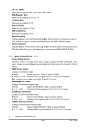
... and reduce the useful life of these components. If this occurs, clear the CMOS values and reset the board to optimize the system voltage settings. BIOS Setup CPU Host Clock Control x CPU Frequency(MHz) PCIE Clock(MHz) HT Link Width HT Link Frequency VGA Core Clock control x VGA Core Clock(MHz... to default values.) • When the System Voltage Optimized item blinks in red, it is dependent on your overall system configurations. This page is for GA-MA785GPMT-UD2H. - 39 -
... and reduce the useful life of these components. If this occurs, clear the CMOS values and reset the board to optimize the system voltage settings. BIOS Setup CPU Host Clock Control x CPU Frequency(MHz) PCIE Clock(MHz) HT Link Width HT Link Frequency VGA Core Clock control x VGA Core Clock(MHz... to default values.) • When the System Voltage Optimized item blinks in red, it is dependent on your overall system configurations. This page is for GA-MA785GPMT-UD2H. - 39 -

Manual
Page 40
...System" will automatically restart for a few seconds and the system will appear. Disabled Disables this function. (Default) Auto Lets the BIOS to configure the settings to take effect. Advanced Clock Calibration Allows you to select the EC firmware version when Advanced Clock Calibration is ...Firmware Selection Allows you to determine whether to enable Advanced Clock Calibration when using an AMD Black Edition CPU. A message which says "BIOS Is Updating EC Firmware!!! Normal Uses the standard AMD EC firmware version. (Default) Hybrid Uses the specific AMD EC firmware version. ...
...System" will automatically restart for a few seconds and the system will appear. Disabled Disables this function. (Default) Auto Lets the BIOS to configure the settings to take effect. Advanced Clock Calibration Allows you to select the EC firmware version when Advanced Clock Calibration is ...Firmware Selection Allows you to determine whether to enable Advanced Clock Calibration when using an AMD Black Edition CPU. A message which says "BIOS Is Updating EC Firmware!!! Normal Uses the standard AMD EC firmware version. (Default) Hybrid Uses the specific AMD EC firmware version. ...

Manual
Page 41
... VGA Core clock. (Default: Disabled) VGA Core Clock(MHz) Allows you to manually set the PCIe clock frequency. Auto (default) allows the BIOS to X4.00. Auto BIOS will automatically adjust the HT Link Width. (Default) 8 bit Sets HT Link Width to 8 bit. 16 bit Sets HT Link Width to...chipset. Auto sets the PCIe clock frequency to standard 100 MHz. (Default: Auto) HT Link Width Allows you to manually set to Manual. Auto BIOS will automatically adjust the HT Link Frequency. (Default) x1~x10 Sets HT Link Frequency to 200 MHz. Manual allows the memory clock control item ...
... VGA Core clock. (Default: Disabled) VGA Core Clock(MHz) Allows you to manually set the PCIe clock frequency. Auto (default) allows the BIOS to X4.00. Auto BIOS will automatically adjust the HT Link Width. (Default) 8 bit Sets HT Link Width to 8 bit. 16 bit Sets HT Link Width to...chipset. Auto sets the PCIe clock frequency to standard 100 MHz. (Default: Auto) HT Link Width Allows you to manually set to Manual. Auto BIOS will automatically adjust the HT Link Frequency. (Default) x1~x10 Sets HT Link Frequency to 200 MHz. Manual allows the memory clock control item ...
Manual
Page 42
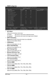
...: General Help F7: Optimized Defaults DCTs Mode Allows you to single dual-channel. Trfc0 for DIMM2 Options are: Auto (default), 90ns, 110ns, 160ns, 300ns, 350ns. BIOS Setup - 42 - Options are : Auto (default), 1T, 2T. Minimum RAS Active Time Options are: Auto (default), 15T~30T. 1T/2T Command Timing Options are : Auto...
...: General Help F7: Optimized Defaults DCTs Mode Allows you to single dual-channel. Trfc0 for DIMM2 Options are: Auto (default), 90ns, 110ns, 160ns, 300ns, 350ns. BIOS Setup - 42 - Options are : Auto (default), 1T, 2T. Minimum RAS Active Time Options are: Auto (default), 15T~30T. 1T/2T Command Timing Options are : Auto...
Manual
Page 43
...to RAS Delay Options are : Auto (default), 90ns, 110ns, 160ns, 300ns, 350ns. Auto lets the BIOS automatically set the system voltages. BIOS Setup Bank Interleaving Enables or disables memory bank interleaving. Enabled allows the system to simultaneously access different banks of ...voltage by 0.1V to 0.2V at 0.1V increment. Note: Increasing memory voltage may result in damage to set the SidePort memory voltage. Trfc3 for GA-MA785GPMT-UD2H. - 43 - Row Cycle Time Options are : Auto (default), 4T~7T. Normal Supplies the North Bridge voltage as required. (Default) +0.1V ...
...to RAS Delay Options are : Auto (default), 90ns, 110ns, 160ns, 300ns, 350ns. Auto lets the BIOS automatically set the system voltages. BIOS Setup Bank Interleaving Enables or disables memory bank interleaving. Enabled allows the system to simultaneously access different banks of ...voltage by 0.1V to 0.2V at 0.1V increment. Note: Increasing memory voltage may result in damage to set the SidePort memory voltage. Trfc3 for GA-MA785GPMT-UD2H. - 43 - Row Cycle Time Options are : Auto (default), 4T~7T. Normal Supplies the North Bridge voltage as required. (Default) +0.1V ...


