Manual
Page 3
...product information, carefully read or download the information on/from the Support&Downloads\Motherboard\Technology Guide page on your motherboard revision before updating motherboard BIOS, drivers, or when looking for technical information. For example, "REV: 1.0" means the revision of this : "REV: X.X." Check ...may be made by copyright laws and is 1.0. Example: For product-related information, check on our website at: http://www.gigabyte.com.tw Identifying Your Motherboard Revision The revision number on our website. Changes to the specifications and features in this manual are...
...product information, carefully read or download the information on/from the Support&Downloads\Motherboard\Technology Guide page on your motherboard revision before updating motherboard BIOS, drivers, or when looking for technical information. For example, "REV: 1.0" means the revision of this : "REV: X.X." Check ...may be made by copyright laws and is 1.0. Example: For product-related information, check on our website at: http://www.gigabyte.com.tw Identifying Your Motherboard Revision The revision number on our website. Changes to the specifications and features in this manual are...
Manual
Page 4
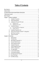
Table of Contents Box Contents...6 Optional Items...6 GA-MA785GPM-UD2H/GA-MA78GM-UD2H(US2H 7 Motherboard Layout...7 Block Diagram...8 Chapter 1 Hardware Installation 9 1-1 Installation Precautions 9 1-2 Product Specifications 10 1-3 Installing the CPU and ...8482; Configuration 19 1-7 Back Panel Connectors 20 1-8 Internal Connectors 23 Chapter 2 BIOS Setup 35 2-1 Startup Screen 36 2-2 The Main Menu 37 2-3 MB Intelligent Tweaker(M.I.T 39 2-4 Standard CMOS Features 44 2-5 Advanced BIOS Features 46 2-6 Integrated Peripherals 49 2-7 Power Management Setup 52 2-8 PnP/PCI Configurations...
Table of Contents Box Contents...6 Optional Items...6 GA-MA785GPM-UD2H/GA-MA78GM-UD2H(US2H 7 Motherboard Layout...7 Block Diagram...8 Chapter 1 Hardware Installation 9 1-1 Installation Precautions 9 1-2 Product Specifications 10 1-3 Installing the CPU and ...8482; Configuration 19 1-7 Back Panel Connectors 20 1-8 Internal Connectors 23 Chapter 2 BIOS Setup 35 2-1 Startup Screen 36 2-2 The Main Menu 37 2-3 MB Intelligent Tweaker(M.I.T 39 2-4 Standard CMOS Features 44 2-5 Advanced BIOS Features 46 2-6 Integrated Peripherals 49 2-7 Power Management Setup 52 2-8 PnP/PCI Configurations...
Manual
Page 5
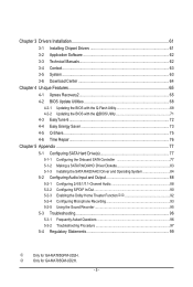
...Manuals 62 3-4 Contact...63 3-5 System...63 3-6 Download Center 64 Chapter 4 Unique Features 65 4-1 Xpress Recovery2 65 4-2 BIOS Update Utilities 68 4-2-1 Updating the BIOS with the Q-Flash Utility 68 4-2-2 Updating the BIOS with the @BIOS Utility 71 4-3 EasyTune 6...72 4-4 Easy Energy Saver 73 4-5 Q-Share...75 4-6 Time Repair...76 Chapter 5 Appendix...77...93 5-2-5 Using the Sound Recorder 95 5-3 Troubleshooting 96 5-3-1 Frequently Asked Questions 96 5-3-2 Troubleshooting Procedure 97 5-4 Regulatory Statements 99 j Only for GA-MA785GM-UD2H. - 5 - k Only for GA-MA785GPM-UD2H.
...Manuals 62 3-4 Contact...63 3-5 System...63 3-6 Download Center 64 Chapter 4 Unique Features 65 4-1 Xpress Recovery2 65 4-2 BIOS Update Utilities 68 4-2-1 Updating the BIOS with the Q-Flash Utility 68 4-2-2 Updating the BIOS with the @BIOS Utility 71 4-3 EasyTune 6...72 4-4 Easy Energy Saver 73 4-5 Q-Share...75 4-6 Time Repair...76 Chapter 5 Appendix...77...93 5-2-5 Using the Sound Recorder 95 5-3 Troubleshooting 96 5-3-1 Frequently Asked Questions 96 5-3-2 Troubleshooting Procedure 97 5-4 Regulatory Statements 99 j Only for GA-MA785GM-UD2H. - 5 - k Only for GA-MA785GPM-UD2H.
Manual
Page 8
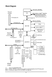
... Express x16 Dual Channel Memory Hyper Transport 3.0 PCI Express x16 PCI Express Bus x1 PCIe CLK (100 MHz) 1 PCI Express x1 RTL8111C RJ45 LAN Dual BIOS PCI Bus TSB43AB23 2 IEEE 1394a AMD 785G GFX CLK (100 MHz) D-Sub DVI-D or HDMI (Note 2) DDR3 SidePort Memoryj 12 USB Ports AMD SB710 ... Speaker Out Center/Subwoofer Speaker Out Side Speaker Out MIC Line Out Line In S/PDIF In S/ PDIF Out 2 PCI PCI CLK (33 MHz) j Only for GA-MA785GPM-UD2H. (Note 1) Whether 1066 MHz or above memory speed is supported depends on the CPU being used. (Note 2) Simultaneous output for DVI-D and HDMI is not...
... Express x16 Dual Channel Memory Hyper Transport 3.0 PCI Express x16 PCI Express Bus x1 PCIe CLK (100 MHz) 1 PCI Express x1 RTL8111C RJ45 LAN Dual BIOS PCI Bus TSB43AB23 2 IEEE 1394a AMD 785G GFX CLK (100 MHz) D-Sub DVI-D or HDMI (Note 2) DDR3 SidePort Memoryj 12 USB Ports AMD SB710 ... Speaker Out Center/Subwoofer Speaker Out Side Speaker Out MIC Line Out Line In S/PDIF In S/ PDIF Out 2 PCI PCI CLK (33 MHz) j Only for GA-MA785GPM-UD2H. (Note 1) Whether 1066 MHz or above memory speed is supported depends on the CPU being used. (Note 2) Simultaneous output for DVI-D and HDMI is not...
Manual
Page 12
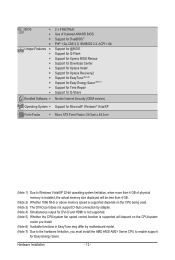
... Features w w w w w w w w w w Bundled Software w 2 x 8 Mbit flash Use of licensed AWARD BIOS Support for DualBIOS™ PnP 1.0a, DMI 2.0, SM BIOS 2.4, ACPI 1.0b Support for @BIOS Support for Q-Flash Support for Xpress BIOS Rescue Support for Download Center Support for Xpress Install Support for Xpress Recovery2 Support for EasyTune (Note 6) Support for Easy Energy Saver (Note...
... Features w w w w w w w w w w Bundled Software w 2 x 8 Mbit flash Use of licensed AWARD BIOS Support for DualBIOS™ PnP 1.0a, DMI 2.0, SM BIOS 2.4, ACPI 1.0b Support for @BIOS Support for Q-Flash Support for Xpress BIOS Rescue Support for Download Center Support for Xpress Install Support for Xpress Recovery2 Support for EasyTune (Note 6) Support for Easy Energy Saver (Note...
Manual
Page 16
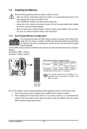
... only one direction. Hardware Installation - 16 - After the memory is recommended that memory of the same capacity, brand, speed, and chips be used . (Go to GIGABYTE's website for optimum performance. Enabling Dual Channel memory mode will automatically detect the specifications and capacity of the same capacity, brand, speed, and chips be... DDR2_4 Two Modules DS/SS DS/SS - - - - - - - - 1-4 Installing the Memory Read the following guidelines before installing the memory to be installed, it is installed, the BIOS will double the original memory bandwidth.
... only one direction. Hardware Installation - 16 - After the memory is recommended that memory of the same capacity, brand, speed, and chips be used . (Go to GIGABYTE's website for optimum performance. Enabling Dual Channel memory mode will automatically detect the specifications and capacity of the same capacity, brand, speed, and chips be... DDR2_4 Two Modules DS/SS DS/SS - - - - - - - - 1-4 Installing the Memory Read the following guidelines before installing the memory to be installed, it is installed, the BIOS will double the original memory bandwidth.
Manual
Page 18
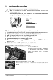
...the metal contacts on the slot and then lift the card straight out from the slot. Secure the card's metal bracket to make any required BIOS changes for your expansion card in the slot. 3. Turn on the top edge of the card until it is securely seated in your expansion ... all expansion cards, replace the chassis cover(s). 6. Install the driver provided with the slot, and press down on your card. If necessary, go to BIOS Setup to the chassis back panel with your operating system. Make sure the card is fully inserted into the slot. 4. Carefully read the manual that...
...the metal contacts on the slot and then lift the card straight out from the slot. Secure the card's metal bracket to make any required BIOS changes for your expansion card in the slot. 3. Turn on the top edge of the card until it is securely seated in your expansion ... all expansion cards, replace the chassis cover(s). 6. Install the driver provided with the slot, and press down on your card. If necessary, go to BIOS Setup to the chassis back panel with your operating system. Make sure the card is fully inserted into the slot. 4. Carefully read the manual that...
Manual
Page 19
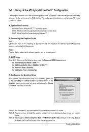
... An ATI Hybrid CrossFireX-supported graphics card (Note 2) B. Set UMA Frame Buffer Size to set the following items under the Advanced BIOS Features menu: - BIOS Setup Enter BIOS Setup to 256MB or 512MB. (Note 3) - Hardware Installation Set Internal Graphics Mode to Disabled. - Select CrossFire™ on the...ATI Hybrid CrossFireX system. stalled. (Note 3) To change the Internal Graphics Mode or UMA Frame Buffer Size setting in BIOS Setup, be sure to install the graphics card driver if the motherboard chipset driver has been in the operating system, go to ...
... An ATI Hybrid CrossFireX-supported graphics card (Note 2) B. Set UMA Frame Buffer Size to set the following items under the Advanced BIOS Features menu: - BIOS Setup Enter BIOS Setup to 256MB or 512MB. (Note 3) - Hardware Installation Set Internal Graphics Mode to Disabled. - Select CrossFire™ on the...ATI Hybrid CrossFireX system. stalled. (Note 3) To change the Internal Graphics Mode or UMA Frame Buffer Size setting in BIOS Setup, be sure to install the graphics card driver if the motherboard chipset driver has been in the operating system, go to ...
Manual
Page 21
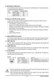
... audio system that your device and then remove it from the motherboard. • When removing the cable, pull it side to side to Chapter 2, "BIOS Setup," "Advanced BIOS Features," for more information) • Playback software: CyberLink PowerDVD 8.0 or later (Note: Please ensure Hardware Acceleration is compatible with dual channel mode enabled •...
... audio system that your device and then remove it from the motherboard. • When removing the cable, pull it side to side to Chapter 2, "BIOS Setup," "Advanced BIOS Features," for more information) • Playback software: CyberLink PowerDVD 8.0 or later (Note: Please ensure Hardware Acceleration is compatible with dual channel mode enabled •...

Manual
Page 28
... way to turn off (S5). • PW (Power Switch, Red): Connects to the power switch on when the hard drive is detected, the BIOS may issue beeps in different patterns to the reset switch on the chassis front panel. Hardware Installation - 28 - You may differ by issuing a beep..., Orange): Connects to the hard drive activity LED on the chassis front panel. When connecting your system using the power switch (refer to Chapter 2, "BIOS Setup," "Power Management Setup," for information about beep codes. • HD (Hard Drive Activity LED, Blue) Connects to the speaker on when the ...
... way to turn off (S5). • PW (Power Switch, Red): Connects to the power switch on when the hard drive is detected, the BIOS may issue beeps in different patterns to the reset switch on the chassis front panel. Hardware Installation - 28 - You may differ by issuing a beep..., Orange): Connects to the hard drive activity LED on the chassis front panel. When connecting your system using the power switch (refer to Chapter 2, "BIOS Setup," "Power Management Setup," for information about beep codes. • HD (Hard Drive Activity LED, Blue) Connects to the speaker on when the ...
Manual
Page 33
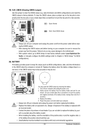
...remove the battery from the jumper. Plug in the CMOS when the computer is replaced with local environmental regulations. - 33 - date information and BIOS configurations) and reset the CMOS values to clear the CMOS values (e.g. Hardware Installation 19) CLR_CMOS (Clearing CMOS Jumper) Use this jumper to ...a screwdriver to touch the two pins for 5 seconds.) 3. Replace the battery when the battery voltage drops to keep the values (such as BIOS configurations, date, and time information) in the power cord and restart your - Failure to do so may cause damage to the motherboard. &#...
...remove the battery from the jumper. Plug in the CMOS when the computer is replaced with local environmental regulations. - 33 - date information and BIOS configurations) and reset the CMOS values to clear the CMOS values (e.g. Hardware Installation 19) CLR_CMOS (Clearing CMOS Jumper) Use this jumper to ...a screwdriver to touch the two pins for 5 seconds.) 3. Replace the battery when the battery voltage drops to keep the values (such as BIOS configurations, date, and time information) in the power cord and restart your - Failure to do so may cause damage to the motherboard. &#...

Manual
Page 35
... necessary power to the CMOS to boot. To upgrade the BIOS, use either the GIGABYTE Q-Flash or @BIOS utility. • Q-Flash allows the user to prevent system instability or other unexpected results. BIOS Setup To see more advanced BIOS Setup menu options, you not flash the BIOS. When the power is recommended that allows the user...
... necessary power to the CMOS to boot. To upgrade the BIOS, use either the GIGABYTE Q-Flash or @BIOS utility. • Q-Flash allows the user to prevent system instability or other unexpected results. BIOS Setup To see more advanced BIOS Setup menu options, you not flash the BIOS. When the power is recommended that allows the user...
Manual
Page 36
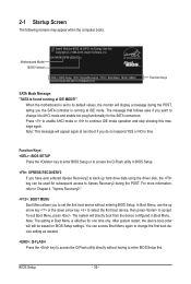
GA-MA785GPM-UD2H E3c . . . . : BIOS Setup : XpressRecovery2 : Boot Menu : Qflash 06/05/2009-RS785-SB710-7A66BG03C-... order will appear again at IDE MODE!" Press to enable AHCI mode or to access the Q-Flash utility in BIOS Setup. : XPRESS RECOVERY2 If you do not respond YES or NO in Boot Menu. For more information, refer... to accept. 2-1 Startup Screen The following screens may appear when the computer boots. Motherboard Model BIOS Version Award Modular BIOS v6.00PG, An Energy Star Ally Copyright (C) 1984-2009, Award Software, Inc. The message that follows...
GA-MA785GPM-UD2H E3c . . . . : BIOS Setup : XpressRecovery2 : Boot Menu : Qflash 06/05/2009-RS785-SB710-7A66BG03C-... order will appear again at IDE MODE!" Press to enable AHCI mode or to access the Q-Flash utility in BIOS Setup. : XPRESS RECOVERY2 If you do not respond YES or NO in Boot Menu. For more information, refer... to accept. 2-1 Startup Screen The following screens may appear when the computer boots. Motherboard Model BIOS Version Award Modular BIOS v6.00PG, An Energy Star Ally Copyright (C) 1984-2009, Award Software, Inc. The message that follows...
Manual
Page 37
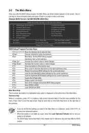
... keys to move among the items and press to accept or enter a sub-menu. (Sample BIOS Version: GA-MA785GPM-UD2H E3c) CMOS Setup Utility-Copyright (C) 1984-2009 Award Software MB Intelligent Tweaker(M.I.T.) Standard CMOS Features Advanced BIOS Features Integrated Peripherals Power Management Setup PnP/PCI Configurations PC Health...
... keys to move among the items and press to accept or enter a sub-menu. (Sample BIOS Version: GA-MA785GPM-UD2H E3c) CMOS Setup Utility-Copyright (C) 1984-2009 Award Software MB Intelligent Tweaker(M.I.T.) Standard CMOS Features Advanced BIOS Features Integrated Peripherals Power Management Setup PnP/PCI Configurations PC Health...

Manual
Page 38
... operations. Set Supervisor Password Change, set , or disable password. It allows you to save the current BIOS settings to a profile. You can create up to the CMOS and exit BIOS Setup. (Pressing can use this task.) Exit Without Saving Abandon all the changes made in effect. A... you can also carry out this function to make changes. Save & Exit Setup Save all changes and the previous settings remain in the BIOS Setup program to 8 profiles (Profile 1-8) and name each profile. First enter the profile name (to erase the default profile name, use the SPACE...
... operations. Set Supervisor Password Change, set , or disable password. It allows you to save the current BIOS settings to a profile. You can create up to the CMOS and exit BIOS Setup. (Pressing can use this task.) Exit Without Saving Abandon all the changes made in effect. A... you can also carry out this function to make changes. Save & Exit Setup Save all changes and the previous settings remain in the BIOS Setup program to 8 profiles (Profile 1-8) and name each profile. First enter the profile name (to erase the default profile name, use the SPACE...
Manual
Page 39
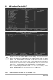
... or other unexpected results. (Inadequately altering the settings may result in damage to CPU, chipset, or memory and reduce the useful life of these components. BIOS Setup
... or other unexpected results. (Inadequately altering the settings may result in damage to CPU, chipset, or memory and reduce the useful life of these components. BIOS Setup
Manual
Page 40
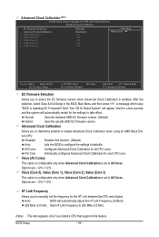
...-12%~+12%. Options are : -12%~+12%. HT Link Frequency Allows you to enable Advanced Clock Calibration when using an AMD Black Edition CPU. BIOS Setup - 40 - Don't Turn Off Or Reset System" will automatically adjust the HT Link Frequency. (Default) 200 MHz~2.0 GHz Sets HT...the EC firmware version when Advanced Clock Calibration is enabled. Per Core Individually configures Advanced Clock Calibration for all CPU cores. Auto BIOS will appear. Disabled Disables this feature. All Cores Configures Advanced Clock Calibration for each CPU core. Wait for a few seconds ...
...-12%~+12%. Options are : -12%~+12%. HT Link Frequency Allows you to enable Advanced Clock Calibration when using an AMD Black Edition CPU. BIOS Setup - 40 - Don't Turn Off Or Reset System" will automatically adjust the HT Link Frequency. (Default) 200 MHz~2.0 GHz Sets HT...the EC firmware version when Advanced Clock Calibration is enabled. Per Core Individually configures Advanced Clock Calibration for all CPU cores. Auto BIOS will appear. Disabled Disables this feature. All Cores Configures Advanced Clock Calibration for each CPU core. Wait for a few seconds ...
Manual
Page 41
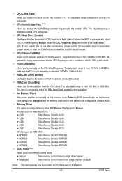
...CPU Frequency (MHz) item below to Manual. Important It is from 100 MHz to be set the memory clock as required. Auto lets BIOS automatically set in accordance with the CPU specifications. X2.66 Sets Memory Clock to default values. Note: If your system fails to boot after...Ratio Allows you install a CPU that the CPU frequency be configurable. Ganged Sets memory control mode to 500 MHz. Auto (default) allows the BIOS to DDR 667. This item is configurable only if the VGA Core Clock control option is dependent on the CPU being used . Unganged Sets memory...
...CPU Frequency (MHz) item below to Manual. Important It is from 100 MHz to be set the memory clock as required. Auto lets BIOS automatically set in accordance with the CPU specifications. X2.66 Sets Memory Clock to default values. Note: If your system fails to boot after...Ratio Allows you install a CPU that the CPU frequency be configurable. Ganged Sets memory control mode to 500 MHz. Auto (default) allows the BIOS to DDR 667. This item is configurable only if the VGA Core Clock control option is dependent on the CPU being used . Unganged Sets memory...

Manual
Page 42
... F7: Optimized Defaults DDRII Timing Items Manual allows all DDR2 Timing items below to be configurable. Write Recovery Time Options are: Auto (default), 3T~6T. BIOS Setup - 42 - DRAM Configuration CMOS Setup Utility-Copyright (C) 1984-2009 Award Software DRAM Configuration DDRII Timing Items x CAS# latency x RAS to CAS R/W Delay x Row Precharge...
... F7: Optimized Defaults DDRII Timing Items Manual allows all DDR2 Timing items below to be configurable. Write Recovery Time Options are: Auto (default), 3T~6T. BIOS Setup - 42 - DRAM Configuration CMOS Setup Utility-Copyright (C) 1984-2009 Award Software DRAM Configuration DDRII Timing Items x CAS# latency x RAS to CAS R/W Delay x Row Precharge...
Manual
Page 43
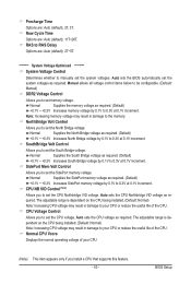
...useful life of your CPU or reduce the useful life of the CPU. CPU Voltage Control Allows you to 0.3V at 0.1V increment. BIOS Setup Normal Supplies the South Bridge voltage as required. (Default) +0.1V ~ +0.3V Increases South Bridge voltage by 0.1V to set memory ...the memory voltage as required. (Default) +0.1V ~ +0.3V Increases SidePort memory voltage by 0.1V to 0.3V at 0.1V increment. Auto lets the BIOS automatically set the system voltages. Normal Supplies the SidePort memory voltage as required. (Default) +0.1V ~ +0.3V Increases memory voltage by 0.1V to manually...
...useful life of your CPU or reduce the useful life of the CPU. CPU Voltage Control Allows you to 0.3V at 0.1V increment. BIOS Setup Normal Supplies the South Bridge voltage as required. (Default) +0.1V ~ +0.3V Increases South Bridge voltage by 0.1V to set memory ...the memory voltage as required. (Default) +0.1V ~ +0.3V Increases SidePort memory voltage by 0.1V to 0.3V at 0.1V increment. Auto lets the BIOS automatically set the system voltages. Normal Supplies the SidePort memory voltage as required. (Default) +0.1V ~ +0.3V Increases memory voltage by 0.1V to manually...


