Manual
Page 4
...GA-MA69VM-S2 Motherboard Layout 7 Block Diagram ...8 Chapter 1 Hardware Installation 9 1-1 Considerations Prior to Installation 9 1-2 Feature Summary 10 1-3 Installation of the CPU and CPU Cooler 12 1-3-1 Installation of the CPU 12 1-3-2 Installation of the CPU cooler 13 1-4 Installation of Memory 14 1-5 Installation of Expansion Cards 16 1-6 I/O Back Panel Introduction 17 1-7 Connectors Introduction 18 Chapter 2 BIOS... Setup 29 The Main Menu (For example: BIOS Ver. : D11 30 2-1 Standard CMOS Features 32 2-2 Advanced BIOS Features 34 2-3 ...
...GA-MA69VM-S2 Motherboard Layout 7 Block Diagram ...8 Chapter 1 Hardware Installation 9 1-1 Considerations Prior to Installation 9 1-2 Feature Summary 10 1-3 Installation of the CPU and CPU Cooler 12 1-3-1 Installation of the CPU 12 1-3-2 Installation of the CPU cooler 13 1-4 Installation of Memory 14 1-5 Installation of Expansion Cards 16 1-6 I/O Back Panel Introduction 17 1-7 Connectors Introduction 18 Chapter 2 BIOS... Setup 29 The Main Menu (For example: BIOS Ver. : D11 30 2-1 Standard CMOS Features 32 2-2 Advanced BIOS Features 34 2-3 ...

Manual
Page 5
Chapter 3 Drivers Installation 47 3-1 Install Chipset Drivers 47 3-2 SoftwareApplication 48 3-3 Software Information 48 3-4 Hardware Information 49 3-5 Contact Us ...49 Chapter 4 Appendix 51 4-1 Unique Software Utilities 51 4-1-1 EasyTune 5 Introduction 51 4-1-2 Xpress Recovery2 Introduction 52 4-1-3 Flash BIOS Method Introduction 54 4-1-4 Configuring SATA Hard Drive(s 58 4-1-5 Installation of TV Output Cable (Optional Device 69 4-1-6 2- / 4- / 6- / 8- Channel Audio Function Introduction 73 4-2 Troubleshooting 78 - 5 -
Chapter 3 Drivers Installation 47 3-1 Install Chipset Drivers 47 3-2 SoftwareApplication 48 3-3 Software Information 48 3-4 Hardware Information 49 3-5 Contact Us ...49 Chapter 4 Appendix 51 4-1 Unique Software Utilities 51 4-1-1 EasyTune 5 Introduction 51 4-1-2 Xpress Recovery2 Introduction 52 4-1-3 Flash BIOS Method Introduction 54 4-1-4 Configuring SATA Hard Drive(s 58 4-1-5 Installation of TV Output Cable (Optional Device 69 4-1-6 2- / 4- / 6- / 8- Channel Audio Function Introduction 73 4-2 Troubleshooting 78 - 5 -
Manual
Page 7
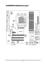
ATX GA-MA69VM-S2 Motherboard Layout MS / KB ATX_12V COMA Socket AM2 LPT VGA CPU_FAN USB USB LAN TV AUDIO IT8716 CI BIOS PCIE_4 GA-MA69VM-S2 AMD 690V F_AUDIO RTL8110SC PCIE_16 PCI1 PCI2 CODEC COMB CD_IN SPDIF_IO DDRII1 DDRII2 DDRII3 DDRII4 IDE SATAII2 SATAII0 AMD SB600 SYS_FAN SATAII3 BATTERY SATAII1 CLR_CMOS F_PANEL F_USB1 F_USB2 F_USB3 PWR_LED FDD - 7 -
ATX GA-MA69VM-S2 Motherboard Layout MS / KB ATX_12V COMA Socket AM2 LPT VGA CPU_FAN USB USB LAN TV AUDIO IT8716 CI BIOS PCIE_4 GA-MA69VM-S2 AMD 690V F_AUDIO RTL8110SC PCIE_16 PCI1 PCI2 CODEC COMB CD_IN SPDIF_IO DDRII1 DDRII2 DDRII3 DDRII4 IDE SATAII2 SATAII0 AMD SB600 SYS_FAN SATAII3 BATTERY SATAII1 CLR_CMOS F_PANEL F_USB1 F_USB2 F_USB3 PWR_LED FDD - 7 -

Manual
Page 11
...fan failure warning Š Supports CPU Smart Fan function(Note 2) BIOS Š 1 4 Mbit flash ROM Š Use of licensed AWARD BIOS Š PnP 1.0a, DMI 2.0, SM BIOS 2.3, ACPI 1.0b Additional Features Š Supports @BIOS Š Supports Download Center Š Supports Q-Flash Š Supports... EasyTune (only supports Hardware Monitor function)(Note 3) Š Supports Xpress Install Š Supports Xpress Recovery2 Š Supports Xpress BIOS Rescue Bundle Software Š Norton Internet Security (OEM version) Form Factor Š Micro ATX form factor; 24.4cm x 24.4cm...
...fan failure warning Š Supports CPU Smart Fan function(Note 2) BIOS Š 1 4 Mbit flash ROM Š Use of licensed AWARD BIOS Š PnP 1.0a, DMI 2.0, SM BIOS 2.3, ACPI 1.0b Additional Features Š Supports @BIOS Š Supports Download Center Š Supports Q-Flash Š Supports... EasyTune (only supports Hardware Monitor function)(Note 3) Š Supports Xpress Install Š Supports Xpress Recovery2 Š Supports Xpress BIOS Rescue Bundle Software Š Norton Internet Security (OEM version) Form Factor Š Micro ATX form factor; 24.4cm x 24.4cm...
Manual
Page 14
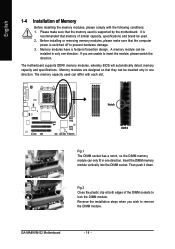
... foolproof insertion design. A memory module can differ with the following conditions: 1. If you wish to prevent hardware damage. 3. GA-MA69VM-S2 Motherboard - 14 - The memory capacity used is recommended that the computer power is switched off to remove the DIMM module.... only in one direction. Then push it down. It is supported by the motherboard. The motherboard supports DDRII memory modules, whereby BIOS will automatically detect memory capacity and specifications. English 1-4 Installation of Memory Before installing the memory modules, please comply with each slot...
... foolproof insertion design. A memory module can differ with the following conditions: 1. If you wish to prevent hardware damage. 3. GA-MA69VM-S2 Motherboard - 14 - The memory capacity used is recommended that the computer power is switched off to remove the DIMM module.... only in one direction. Then push it down. It is supported by the motherboard. The motherboard supports DDRII memory modules, whereby BIOS will automatically detect memory capacity and specifications. English 1-4 Installation of Memory Before installing the memory modules, please comply with each slot...
Manual
Page 16
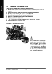
... Please align the VGA card to the onboard PCI Express x16 slot and press firmly down on the computer, if necessary, setup BIOS utility of expansion card from the operating system. Be sure the metal contacts on the card are indeed seated in motherboard. 4. .... Read the related expansion card's instruction document before install the expansion card into expansion slot in the slot. 5. Install related driver from BIOS. 8. GA-MA69VM-S2 Motherboard - 16 - Press the expansion card firmly into the computer. 2. Installing a PCI Express x16 expansion card: Please carefully pull out...
... Please align the VGA card to the onboard PCI Express x16 slot and press firmly down on the computer, if necessary, setup BIOS utility of expansion card from the operating system. Be sure the metal contacts on the card are indeed seated in motherboard. 4. .... Read the related expansion card's instruction document before install the expansion card into expansion slot in the slot. 5. Install related driver from BIOS. 8. GA-MA69VM-S2 Motherboard - 16 - Press the expansion card firmly into the computer. 2. Installing a PCI Express x16 expansion card: Please carefully pull out...

Manual
Page 21
English 6) IDE (IDE Connector) An IDE device connects to connect two IDE devices, please set the jumper on the IDE device). Please refer to the BIOS setting for information on settings, please refer to the instructions located on one IDE cable, and the single IDE cable can connect to one IDE ...
English 6) IDE (IDE Connector) An IDE device connects to connect two IDE devices, please set the jumper on the IDE device). Please refer to the BIOS setting for information on settings, please refer to the instructions located on one IDE cable, and the single IDE cable can connect to one IDE ...
Manual
Page 24
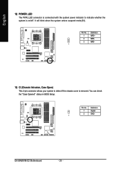
You can check the "Case Opened" status in BIOS Setup. Pin No. English 12) POWER_LED The PWR_LED connector is connected with the system power indicator to detect if the chassis cover is on/off. Definition 1 MPD+ 2 MPD- 3 MPD- 1 13) CI (Chassis Intrusion, Case Open) This 2-pin connector allows your system to indicate whether the system is removed. Definition 1 Signal 2 GND 1 GA-MA69VM-S2 Motherboard - 24 - Pin No. It will blink when the system enters suspend mode(S1).
You can check the "Case Opened" status in BIOS Setup. Pin No. English 12) POWER_LED The PWR_LED connector is connected with the system power indicator to detect if the chassis cover is on/off. Definition 1 MPD+ 2 MPD- 3 MPD- 1 13) CI (Chassis Intrusion, Case Open) This 2-pin connector allows your system to indicate whether the system is removed. Definition 1 Signal 2 GND 1 GA-MA69VM-S2 Motherboard - 24 - Pin No. It will blink when the system enters suspend mode(S1).
Manual
Page 29
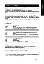
... features. Exit current page and return to select item Select Item Main Menu - To exit the Help Window press . Because BIOS flashing is a Windows-based utility that describes the appropriate keys to the CMOS SRAM. CONTROL KEYS Move to Main Menu Increase... in system malfunction. - 29 - English Chapter 2 BIOS Setup BIOS (Basic Input and Output System) includes a CMOS SETUP utility which allows user to configure required settings or to a new BIOS, either GIGABYTE's Q-Flash or @BIOS utility can enter the BIOS setup screen by pressing "Ctrl + F1". Quit and...
... features. Exit current page and return to select item Select Item Main Menu - To exit the Help Window press . Because BIOS flashing is a Windows-based utility that describes the appropriate keys to the CMOS SRAM. CONTROL KEYS Move to Main Menu Increase... in system malfunction. - 29 - English Chapter 2 BIOS Setup BIOS (Basic Input and Output System) includes a CMOS SETUP utility which allows user to configure required settings or to a new BIOS, either GIGABYTE's Q-Flash or @BIOS utility can enter the BIOS setup screen by pressing "Ctrl + F1". Quit and...
Manual
Page 30
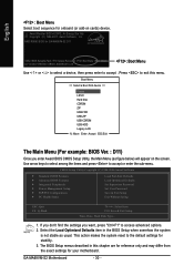
... when somehow the system is not stable as figure below) will appear on cards) device. GA-MA69VM-S2 Motherboard - 30 - If you don't find the settings you enter Award BIOS CMOS Setup Utility, the Main Menu (as usual. Press to exit this chapter are for reference only and may differ ...from the exact settings for GA-MA69VM-S2 D11 . . . . :BIOS Setup/Q-Flash :Xpress Recovery2 :Boot Menu :Qflash 02/14/2007-RS690V-SB600-6A669G01C-00 : Boot Menu Use < > or < > to select a device, ...
... when somehow the system is not stable as figure below) will appear on cards) device. GA-MA69VM-S2 Motherboard - 30 - If you don't find the settings you enter Award BIOS CMOS Setup Utility, the Main Menu (as usual. Press to exit this chapter are for reference only and may differ ...from the exact settings for GA-MA69VM-S2 D11 . . . . :BIOS Setup/Q-Flash :Xpress Recovery2 :Boot Menu :Qflash 02/14/2007-RS690V-SB600-6A669G01C-00 : Boot Menu Use < > or < > to select a device, ...

Manual
Page 31
... system. „ Save & Exit Setup Save CMOS value settings to Setup. „ Set User Password Change, set , or disable password. BIOS Setup It allows you to limit access to the system and Setup, or just to CMOS and exit setup. „ Exit Without Saving Abandon ...value changes and exit setup. - 31 - English „ Standard CMOS Features This setup page includes all the items in standard compatible BIOS. „ Advanced BIOS Features This setup page includes all the items of Award special enhanced features. „ Integrated Peripherals This setup page includes all onboard peripherals...
... system. „ Save & Exit Setup Save CMOS value settings to Setup. „ Set User Password Change, set , or disable password. BIOS Setup It allows you to limit access to the system and Setup, or just to CMOS and exit setup. „ Exit Without Saving Abandon ...value changes and exit setup. - 31 - English „ Standard CMOS Features This setup page includes all the items in standard compatible BIOS. „ Advanced BIOS Features This setup page includes all the items of Award special enhanced features. „ Integrated Peripherals This setup page includes all onboard peripherals...
Manual
Page 32
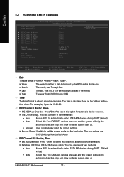
is calculated base on the 24-hour militarytime clock. GA-MA69VM-S2 Motherboard - 32 - The time is 13:00:00. IDE Device Setup. ... for faster system start up . • Manual User can use one of two methods: • Auto Allows BIOS to 31 (or the maximum allowed in . Through Dec. Week Month The week, from 2000 through 2099 Time The... CHS/LBA/Large/Auto(default:Auto) IDE Channel 2/3 Master, Slave IDE Auto-Detection Press "Enter" to Sat, determined by the BIOS and is , , , . English 2-1 Standard CMOS Features Date (mm:dd:yy) Time (hh:mm:ss) CMOS Setup Utility-...
is calculated base on the 24-hour militarytime clock. GA-MA69VM-S2 Motherboard - 32 - The time is 13:00:00. IDE Device Setup. ... for faster system start up . • Manual User can use one of two methods: • Auto Allows BIOS to 31 (or the maximum allowed in . Through Dec. Week Month The week, from 2000 through 2099 Time The... CHS/LBA/Large/Auto(default:Auto) IDE Channel 2/3 Master, Slave IDE Auto-Detection Press "Enter" to Sat, determined by the BIOS and is , , , . English 2-1 Standard CMOS Features Date (mm:dd:yy) Time (hh:mm:ss) CMOS Setup Utility-...
Manual
Page 33
...errors. Enter the appropriate option based on the motherboard. Halt on the outside drive casing. it will determine the amount of the BIOS. Hard drive information should be detected and you will not stop for the hard drive. Base Memory The POST of the base ...) of base (or conventional) memory installed in the computer. it will not stop for a keyboard error; BIOS Setup English Access Mode Use this information. All Errors Whenever the BIOS detects a non-fatal error the system will be stopped. (Default value) All, But Keyboard The system boot...
...errors. Enter the appropriate option based on the motherboard. Halt on the outside drive casing. it will determine the amount of the BIOS. Hard drive information should be detected and you will not stop for the hard drive. Base Memory The POST of the base ...) of base (or conventional) memory installed in the computer. it will not stop for a keyboard error; BIOS Setup English Access Mode Use this information. All Errors Whenever the BIOS detects a non-fatal error the system will be stopped. (Default value) All, But Keyboard The system boot...
Manual
Page 34
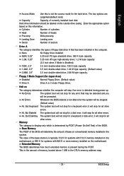
... this menu. Hard Disk Select your boot device priority by Hard Disk. USB-CDROM Select your boot device priority by USB-CDROM. GA-MA69VM-S2 Motherboard - 34 - Hard Disk Boot Priority Select boot sequence for onboard(or add-on cards) SCSI, RAID, etc. LS120 Select... your boot device priority by LS120. Disabled Disable this function. English 2-2 Advanced BIOS Features CMOS Setup Utility-Copyright (C) 1984-2007 Award Software Advanced BIOS Features AMD K8 Cool&Quiet control ` Hard Disk Boot Priority First Boot Device Second Boot Device Third ...
... this menu. Hard Disk Select your boot device priority by Hard Disk. USB-CDROM Select your boot device priority by USB-CDROM. GA-MA69VM-S2 Motherboard - 34 - Hard Disk Boot Priority Select boot sequence for onboard(or add-on cards) SCSI, RAID, etc. LS120 Select... your boot device priority by LS120. Disabled Disable this function. English 2-2 Advanced BIOS Features CMOS Setup Utility-Copyright (C) 1984-2007 Award Software Advanced BIOS Features AMD K8 Cool&Quiet control ` Hard Disk Boot Priority First Boot Device Second Boot Device Third ...

Manual
Page 35
... card is installed. Internal Graphics Mode Auto Enable output from 720K, 1.2M or 1.44M drive type as they are all 80 tracks. BIOS Setup Capability This feature allows your hard disk to report read/write errors and to determine it is installed, automatically output from which card ...Default value) Enable the Dual-View capability. Set frame buffer size to 256 MB. 512MB 1024MB Set frame buffer size to onboard VGA. Disabled BIOS will not search for floppy disk drive to issue warnings when third- Setup The system will be denied if the correct password is installed. ...
... card is installed. Internal Graphics Mode Auto Enable output from 720K, 1.2M or 1.44M drive type as they are all 80 tracks. BIOS Setup Capability This feature allows your hard disk to report read/write errors and to determine it is installed, automatically output from which card ...Default value) Enable the Dual-View capability. Set frame buffer size to 256 MB. 512MB 1024MB Set frame buffer size to onboard VGA. Disabled BIOS will not search for floppy disk drive to issue warnings when third- Setup The system will be denied if the correct password is installed. ...

Manual
Page 37
... storage detect This option allows users to decide whether to invoke the boot ROM of the onboard LAN chip. Onboard Serial Port 2 Auto BIOS will automatically setup the port 1 address. 3F8/IRQ4 Enable onboard Serial port 1 and address is 3F8/IRQ4. (Default value) 2F8/IRQ3... Onboard LAN Boot ROM This function decide whether to detect USB storage devices, including USB flash drives and USB hard drives during POST. Enabled BIOS will scan all USB storage devices. (Default value) Disabled Disable this function. (Default value) OnChip USB Controller Enable Disabled Enable USB 1.1 ...
... storage detect This option allows users to decide whether to invoke the boot ROM of the onboard LAN chip. Onboard Serial Port 2 Auto BIOS will automatically setup the port 1 address. 3F8/IRQ4 Enable onboard Serial port 1 and address is 3F8/IRQ4. (Default value) 2F8/IRQ3... Onboard LAN Boot ROM This function decide whether to detect USB storage devices, including USB flash drives and USB hard drives during POST. Enabled BIOS will scan all USB storage devices. (Default value) Disabled Disable this function. (Default value) OnChip USB Controller Enable Disabled Enable USB 1.1 ...

Manual
Page 39
... Disabled Enter from any suspend state. Disable this function. Soft-Off by Alarm x Date (of Month) x Resume Time (hh:mm:ss) [S1(POS)] [Instant-off . BIOS Setup
... Disabled Enter from any suspend state. Disable this function. Soft-Off by Alarm x Date (of Month) x Resume Time (hh:mm:ss) [S1(POS)] [Instant-off . BIOS Setup

Manual
Page 41
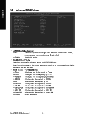
BIOS Setup Auto assign IRQ to PCI 2. (Default value) Set IRQ 3,4,5,7,9,10,11,12,14,15 to PCI 1. English 2-5 PnP/PCI Configurations CMOS Setup Utility-Copyright (C) ...
BIOS Setup Auto assign IRQ to PCI 2. (Default value) Set IRQ 3,4,5,7,9,10,11,12,14,15 to PCI 1. English 2-5 PnP/PCI Configurations CMOS Setup Utility-Copyright (C) ...

Manual
Page 43
... value) CPU Smart FAN Mode This option is available only when CPU Smart FAN Control is enabled, CPU fan will depend on CPU temperature. BIOS Setup Auto BIOS autodetects the type of CPU fan you installed and sets the optimal CPU Smart FAN control mode for it. (Default Value) Voltage Set to...
... value) CPU Smart FAN Mode This option is available only when CPU Smart FAN Control is enabled, CPU fan will depend on CPU temperature. BIOS Setup Auto BIOS autodetects the type of CPU fan you installed and sets the optimal CPU Smart FAN control mode for it. (Default Value) Voltage Set to...
Manual
Page 44
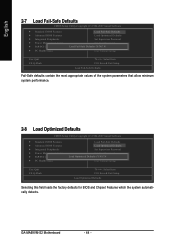
...system parameters that allow minimum system performance. 2-8 Load Optimized Defaults CMOS Setup Utility-Copyright (C) 1984-2007 Award Software ` Standard CMOS Features ` Advanced BIOS Features ` Integrated Peripherals ` Power Management Setup ` PnP/PCI Configurations ` PC Health Status Load Fail-Safe Defaults Load Optimized Defaults Set Supervisor Password Set... F8: Q-Flash KLJI: Select Item F10: Save & Exit Setup Load Optimized Defaults Selecting this field loads the factory defaults for BIOS and Chipset Features which the system automatically detects. GA-MA69VM-S2 Motherboard - 44 -
...system parameters that allow minimum system performance. 2-8 Load Optimized Defaults CMOS Setup Utility-Copyright (C) 1984-2007 Award Software ` Standard CMOS Features ` Advanced BIOS Features ` Integrated Peripherals ` Power Management Setup ` PnP/PCI Configurations ` PC Health Status Load Fail-Safe Defaults Load Optimized Defaults Set Supervisor Password Set... F8: Q-Flash KLJI: Select Item F10: Save & Exit Setup Load Optimized Defaults Selecting this field loads the factory defaults for BIOS and Chipset Features which the system automatically detects. GA-MA69VM-S2 Motherboard - 44 -


