Manual
Page 1
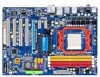
GA-M720-US3 AM2+/AM2 socket motherboard for AMD PhenomTM FX processor/AMD PhenomTM X4 processor/ AMD PhenomTM X3 processor/AMD AthlonTM X2 processor/ AMD AthlonTM processor/AMD SempronTM X2 processor/ AMD SempronTM processor User's Manual Rev. 1002 12ME-M720US3-1002R
GA-M720-US3 AM2+/AM2 socket motherboard for AMD PhenomTM FX processor/AMD PhenomTM X4 processor/ AMD PhenomTM X3 processor/AMD AthlonTM X2 processor/ AMD AthlonTM processor/AMD SempronTM X2 processor/ AMD SempronTM processor User's Manual Rev. 1002 12ME-M720US3-1002R
Manual
Page 3
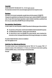
...the following types of documentations: For quick set-up of the motherboard is the property of this manual may be made by any form or by GIGABYTE without GIGABYTE's prior written permission. For example, "REV: 1.0" means the revision of the product, read the Quick ...with the product. For detailed product information, carefully read the User's Manual. For instructions on how to assist in this : "REV: X.X." The trademarks mentioned in the use GIGABYTE's unique features, read or download the information on/from the Support\Motherboard\Technology...
...the following types of documentations: For quick set-up of the motherboard is the property of this manual may be made by any form or by GIGABYTE without GIGABYTE's prior written permission. For example, "REV: 1.0" means the revision of the product, read the Quick ...with the product. For detailed product information, carefully read the User's Manual. For instructions on how to assist in this : "REV: X.X." The trademarks mentioned in the use GIGABYTE's unique features, read or download the information on/from the Support\Motherboard\Technology...
Manual
Page 6
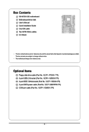
... bracket (Part No. 12CF1-1IE008-0*R) 2-port SATA power cable (Part No. 12CF1-2SERPW-0*R) COM port cable (Part No. 12CF1-1CM001-3*R) - 6 - Box Contents GA-M720-US3 motherboard Motherboard driver disk User's Manual Quick Installation Guide One IDE cable Two SATA 3Gb/s cables I/O Shield • The box contents above are subject to change without notice. •...
... bracket (Part No. 12CF1-1IE008-0*R) 2-port SATA power cable (Part No. 12CF1-2SERPW-0*R) COM port cable (Part No. 12CF1-1CM001-3*R) - 6 - Box Contents GA-M720-US3 motherboard Motherboard driver disk User's Manual Quick Installation Guide One IDE cable Two SATA 3Gb/s cables I/O Shield • The box contents above are subject to change without notice. •...
Manual
Page 9
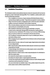
... motherboard, please have a problem related to the use of the product, please consult a certified computer technician. - 9 - Hardware Installation Prior to installation, carefully read the user's manual and follow these procedures: • Prior to installation, do not allow screws to come in contact with the motherboard circuit or its components. • Make...
... motherboard, please have a problem related to the use of the product, please consult a certified computer technician. - 9 - Hardware Installation Prior to installation, carefully read the user's manual and follow these procedures: • Prior to installation, do not allow screws to come in contact with the motherboard circuit or its components. • Make...
Manual
Page 14
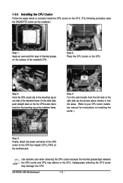
Step 2: Place the CPU cooler on the surface of the installed CPU. Inadequately removing the CPU cooler may adhere to the CPU. GA-M720-US3 Motherboard - 14 - On the other side, push straight down on the the CPU cooler clip to hook it to the CPU fan header (CPU_FAN) on ... CPU cooler clip to correctly install the CPU cooler on the CPU. (The following procedure uses the GIGABYTE cooler as the picture above shows) to lock into place. (Refer to your CPU cooler installation manual for instructions on installing the cooler.) Step 5: Finally, attach the power connector of the CPU cooler ...
Step 2: Place the CPU cooler on the surface of the installed CPU. Inadequately removing the CPU cooler may adhere to the CPU. GA-M720-US3 Motherboard - 14 - On the other side, push straight down on the the CPU cooler clip to hook it to the CPU fan header (CPU_FAN) on ... CPU cooler clip to correctly install the CPU cooler on the CPU. (The following procedure uses the GIGABYTE cooler as the picture above shows) to lock into place. (Refer to your CPU cooler installation manual for instructions on installing the cooler.) Step 5: Finally, attach the power connector of the CPU cooler ...
Manual
Page 17
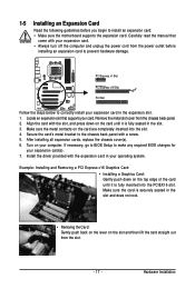
..., go to BIOS Setup to prevent hardware damage. Turn on the card until it is fully inserted into the slot. 4. Hardware Installation Carefully read the manual that supports your expansion card. • Always turn off the computer and unplug the power cord from the chassis back panel. 2. Locate an expansion slot...
..., go to BIOS Setup to prevent hardware damage. Turn on the card until it is fully inserted into the slot. 4. Hardware Installation Carefully read the manual that supports your expansion card. • Always turn off the computer and unplug the power cord from the chassis back panel. 2. Locate an expansion slot...
Manual
Page 27
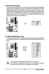
.... Each USB header can provide two USB ports via an optional USB bracket. For information about connecting the S/PDIF digital audio cable, carefully read the manual for your graphics card if you wish to connect an HDMI display to the graphics card and have digital audio output from the HDMI display...
.... Each USB header can provide two USB ports via an optional USB bracket. For information about connecting the S/PDIF digital audio cable, carefully read the manual for your graphics card if you wish to connect an HDMI display to the graphics card and have digital audio output from the HDMI display...
Manual
Page 29
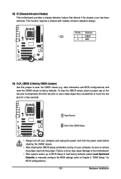
... do so may cause damage to the motherboard. • After system restart, go to BIOS Setup to load factory defaults (select Load Optimized Defaults) or manually configure the BIOS settings (refer to remove the jumper cap from the power outlet before clearing the CMOS values. • After clearing the CMOS values...
... do so may cause damage to the motherboard. • After system restart, go to BIOS Setup to load factory defaults (select Load Optimized Defaults) or manually configure the BIOS settings (refer to remove the jumper cap from the power outlet before clearing the CMOS values. • After clearing the CMOS values...
Manual
Page 35
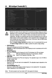
... is recommended that the CPU frequency be set in accordance with the overclock/overvoltage settings you made is present only if you to manually set the System Voltage Control item to Auto to optimize the system voltage settings. CPU NorthBridge Freq. (Note) Allows you set ...to alter the North Bridge controller frequency for the installed CPU. The adjustable range is for advanced users only and we recommend you to manually set the PCIe clock frequency. 2-3 MB Intelligent Tweaker(M.I.T.) CMOS Setup Utility-Copyright (C) 1984-2008 Award Software MB Intelligent Tweaker(M.I.T.) CPU ...
... is recommended that the CPU frequency be set in accordance with the overclock/overvoltage settings you made is present only if you to manually set the System Voltage Control item to Auto to optimize the system voltage settings. CPU NorthBridge Freq. (Note) Allows you set ...to alter the North Bridge controller frequency for the installed CPU. The adjustable range is for advanced users only and we recommend you to manually set the PCIe clock frequency. 2-3 MB Intelligent Tweaker(M.I.T.) CMOS Setup Utility-Copyright (C) 1984-2008 Award Software MB Intelligent Tweaker(M.I.T.) CPU ...
Manual
Page 36
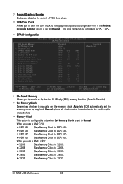
Manual allows all clock control items below to DDR 400. DDR 667 Sets Memory Clock to X3.33. ...Set Memory Clock is set to X2.00. X2.66 Sets Memory Clock to DDR 533. GA-M720-US3 Motherboard - 36 - Auto - - When you use a AM2+ CPU: X2.00 Sets Memory Clock to Manual. Auto 6T Auto 3T Auto 21T Auto 3T Auto 5T 5T 5T 15T - 3T 105ns ... DIMM3 x Trfc3 for the graphics chip and is configurable only if the Robust Graphics Booster option is set to manually set the memory clock as required. Robust Graphics Booster Enables or disables the control of VGA Core clock.
Manual allows all clock control items below to DDR 400. DDR 667 Sets Memory Clock to X3.33. ...Set Memory Clock is set to X2.00. X2.66 Sets Memory Clock to DDR 533. GA-M720-US3 Motherboard - 36 - Auto - - When you use a AM2+ CPU: X2.00 Sets Memory Clock to Manual. Auto 6T Auto 3T Auto 21T Auto 3T Auto 5T 5T 5T 15T - 3T 105ns ... DIMM3 x Trfc3 for the graphics chip and is configurable only if the Robust Graphics Booster option is set to manually set the memory clock as required. Robust Graphics Booster Enables or disables the control of VGA Core clock.
Manual
Page 37
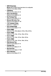
Options are : Auto (default), 3T~6T. Write Recovery Time Options are : Auto (default), Manual. RAS to CAS R/W Delay Options are : 75ns, 105ns (default), 127.5ns, 195ns, 327.5ns. Trfc0 for DIMM2 Options are : Auto (default), 1T~3T. BIOS Setup ..., 195ns, 327.5ns. Trfc3 for DIMM3 Options are : 1T (default), 2T. Precharge Time Options are : 75ns, 105ns, 127.5ns, 195ns, 327.5ns. DDRII Timing Items Manual allows all DDRII Timing items below to RAS Delay Options are : Auto (default), 11T~26T. Minimum RAS Active Time Options are: Auto (default), 5T~18T...
Options are : Auto (default), 3T~6T. Write Recovery Time Options are : Auto (default), Manual. RAS to CAS R/W Delay Options are : 75ns, 105ns (default), 127.5ns, 195ns, 327.5ns. Trfc0 for DIMM2 Options are : Auto (default), 1T~3T. BIOS Setup ..., 195ns, 327.5ns. Trfc3 for DIMM3 Options are : 1T (default), 2T. Precharge Time Options are : 75ns, 105ns, 127.5ns, 195ns, 327.5ns. DDRII Timing Items Manual allows all DDRII Timing items below to RAS Delay Options are : Auto (default), 11T~26T. Minimum RAS Active Time Options are: Auto (default), 5T~18T...
Manual
Page 38
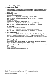
... Increases memory voltage by 0.1V to 0.2V at 0.1V increment. CPU NB VID Control (Note) Allows you to set memory voltage. GA-M720-US3 Motherboard - 38 - Normal CPU Vcore Displays the normal operating voltage of your CPU or reduce the useful life of the CPU. Normal ...~ +0.2V Increases memory voltage by 0.1V to 0.2V at 0.1V increment. ******** System Voltage Optimized ******** System Voltage Control Determines whether to manually set the CPU North Bridge voltage. The adjustable range is dependent on the CPU being installed. (Default: Normal) Note: Increasing CPU voltage ...
... Increases memory voltage by 0.1V to 0.2V at 0.1V increment. CPU NB VID Control (Note) Allows you to set memory voltage. GA-M720-US3 Motherboard - 38 - Normal CPU Vcore Displays the normal operating voltage of your CPU or reduce the useful life of the CPU. Normal ...~ +0.2V Increases memory voltage by 0.1V to 0.2V at 0.1V increment. ******** System Voltage Optimized ******** System Voltage Control Determines whether to manually set the CPU North Bridge voltage. The adjustable range is dependent on the CPU being installed. (Default: Normal) Note: Increasing CPU voltage ...
Manual
Page 39
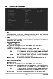
...or down arrow key to None so the system will skip the detection of the device during the POST for faster system startup. • Manual Allows you to CHS. Select the desired field and use the up arrow or down arrow key to set the date. Access Mode Sets ... 0 Master/Slave Configure your IDE/SATA devices by using one of the device during the POST for faster system startup. Options are used , set to manually enter the specifications of the two methods below : • Auto • None Lets BIOS automatically detect IDE/SATA devices during the POST. (Default) •...
...or down arrow key to None so the system will skip the detection of the device during the POST for faster system startup. • Manual Allows you to CHS. Select the desired field and use the up arrow or down arrow key to set the date. Access Mode Sets ... 0 Master/Slave Configure your IDE/SATA devices by using one of the device during the POST for faster system startup. Options are used , set to manually enter the specifications of the two methods below : • Auto • None Lets BIOS automatically detect IDE/SATA devices during the POST. (Default) •...
Manual
Page 40
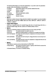
... hard drive. Landing Zone Landing zone. Sector Number of extended memory. Drive A Allows you wish to enter the parameters manually, refer to determine whether the system will stop for any error. Extended Memory The amount of sectors. Head Number of cylinders...your hard drive specifications. All Errors Whenever the BIOS detects a non-fatal error the system boot will stop for all other errors. GA-M720-US3 Motherboard - 40 - Base Memory Also called conventional memory. Options are determined by the BIOS POST. Options are: Disabled (default), ...
... hard drive. Landing Zone Landing zone. Sector Number of extended memory. Drive A Allows you wish to enter the parameters manually, refer to determine whether the system will stop for any error. Extended Memory The amount of sectors. Head Number of cylinders...your hard drive specifications. All Errors Whenever the BIOS detects a non-fatal error the system boot will stop for all other errors. GA-M720-US3 Motherboard - 40 - Base Memory Also called conventional memory. Options are determined by the BIOS POST. Options are: Disabled (default), ...
Manual
Page 62
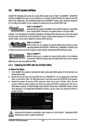
... motherboard features the DualBIOSTM design, which enhances protection for the safety and stability of system safety, users cannot update the backup BIOS manually. Motherboards that matches your floppy disk, USB flash drive, or hard drive. What is potentially risky, please do it with the... like MS-DOS or Window first. GA-M720-US3 Motherboard - 62 - Before You Begin: 1. What is corrupted or damaged, the backup BIOS will download the latest BIOS file from the hassles of going through complicated BIOS flashing process. From GIGABYTE's website, download the latest compressed BIOS...
... motherboard features the DualBIOSTM design, which enhances protection for the safety and stability of system safety, users cannot update the backup BIOS manually. Motherboards that matches your floppy disk, USB flash drive, or hard drive. What is potentially risky, please do it with the... like MS-DOS or Window first. GA-M720-US3 Motherboard - 62 - Before You Begin: 1. What is corrupted or damaged, the backup BIOS will download the latest BIOS file from the hassles of going through complicated BIOS flashing process. From GIGABYTE's website, download the latest compressed BIOS...
Manual
Page 65
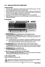
...Features Follow the onscreen instructions to save the BIOS update file obtained from GIGABYTE Server, select the @BIOS server site closest to start. 3. Follow the on the @BIOS server site, please manually download the BIOS update file from an inadequate BIOS flashing. Do not ...use the G.O.M. (GIGABYTE Online Management) function when using @BIOS. 4. B. Before You Begin: 1. GIGABYTE product warranty does not cover any BIOS damage or system failure...
...Features Follow the onscreen instructions to save the BIOS update file obtained from GIGABYTE Server, select the @BIOS server site closest to start. 3. Follow the on the @BIOS server site, please manually download the BIOS update file from an inadequate BIOS flashing. Do not ...use the G.O.M. (GIGABYTE Online Management) function when using @BIOS. 4. B. Before You Begin: 1. GIGABYTE product warranty does not cover any BIOS damage or system failure...
Manual
Page 71
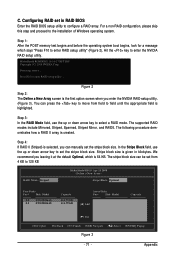
... POST memory test begins and before the operating system boot begins, look for a message which is created. Define a New Array - The stripe block size can manually set in kilobytes. Hit the key to enter RAID setup utility" (Figure 2). Detecting arrays ... Figure 2 Step 2: The Define a New Array screen is given in RAID...
... POST memory test begins and before the operating system boot begins, look for a message which is created. Define a New Array - The stripe block size can manually set in kilobytes. Hit the key to enter RAID setup utility" (Figure 2). Detecting arrays ... Figure 2 Step 2: The Define a New Array screen is given in RAID...
Manual
Page 79
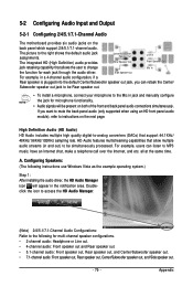
... In The integrated HD (High Definition) audio provides Rear Speaker Out Front Speaker Out jack retasking capability that allow multiple audio streams (in jack and manually configure the jack for multi-channel speaker configurations. • 2-channel audio: Headphone or Line out. • 4-channel audio: Front speaker out and Rear speaker out...
... In The integrated HD (High Definition) audio provides Rear Speaker Out Front Speaker Out jack retasking capability that allow multiple audio streams (in jack and manually configure the jack for multi-channel speaker configurations. • 2-channel audio: Headphone or Line out. • 4-channel audio: Front speaker out and Rear speaker out...
Manual
Page 88
... product. GA-M720-US3 Motherboard - 88 - Also note that protects human health and the environment. Our Commitment to Preserving the Environment In addition to maximize the use internationally banned toxic chemicals. Instead, the device should not be construed as a commitment by GIGABYTE. To ...to develop products that this document is recycled in your product's user's manual and we at the Customer Care number listed in a manner that the information in all GIGABYTE motherboards fulfill European Union regulations for RoHS (Restriction of Certain Hazardous Substances ...
... product. GA-M720-US3 Motherboard - 88 - Also note that protects human health and the environment. Our Commitment to Preserving the Environment In addition to maximize the use internationally banned toxic chemicals. Instead, the device should not be construed as a commitment by GIGABYTE. To ...to develop products that this document is recycled in your product's user's manual and we at the Customer Care number listed in a manner that the information in all GIGABYTE motherboards fulfill European Union regulations for RoHS (Restriction of Certain Hazardous Substances ...


