Manual
Page 3
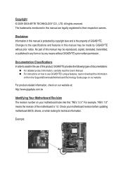
... updating motherboard BIOS, drivers, or when looking for technical information. Copyright © 2009 GIGA-BYTE TECHNOLOGY CO., LTD. The trademarks mentioned in this manual are legally registered to the specifications and features in any form or by any means without prior notice. Changes to their respective owners. For example, "REV: 1.0" means the revision of GIGABYTE. Example: Disclaimer Information in the use GIGABYTE...
... updating motherboard BIOS, drivers, or when looking for technical information. Copyright © 2009 GIGA-BYTE TECHNOLOGY CO., LTD. The trademarks mentioned in this manual are legally registered to the specifications and features in any form or by any means without prior notice. Changes to their respective owners. For example, "REV: 1.0" means the revision of GIGABYTE. Example: Disclaimer Information in the use GIGABYTE...
Manual
Page 4
...of Contents Box Contents...6 Optional Items...6 GA-M68M-S2P Motherboard Layout 7 Block Diagram...8 Chapter 1 Hardware Installation 9 1-1 Installation Precautions 9 1-2 Product Specifications 10 1-3 Installing the CPU and CPU Cooler 13 1-3-1 Installing the CPU 13 1-3-2 Installing the CPU Cooler 15 1-4 Installing the Memory 16 1-4-1 Dual Channel Memory Configuration 16 1-4-2 Installing a Memory 17 1-5 Installing an Expansion Card 18 1-6 Back Panel Connectors 19 1-7 Internal Connectors 21 Chapter 2 BIOS Setup 29 2-1 Startup Screen 30 2-2 The Main Menu 31 2-3 MB Intelligent Tweaker...
...of Contents Box Contents...6 Optional Items...6 GA-M68M-S2P Motherboard Layout 7 Block Diagram...8 Chapter 1 Hardware Installation 9 1-1 Installation Precautions 9 1-2 Product Specifications 10 1-3 Installing the CPU and CPU Cooler 13 1-3-1 Installing the CPU 13 1-3-2 Installing the CPU Cooler 15 1-4 Installing the Memory 16 1-4-1 Dual Channel Memory Configuration 16 1-4-2 Installing a Memory 17 1-5 Installing an Expansion Card 18 1-6 Back Panel Connectors 19 1-7 Internal Connectors 21 Chapter 2 BIOS Setup 29 2-1 Startup Screen 30 2-2 The Main Menu 31 2-3 MB Intelligent Tweaker...
Manual
Page 5
... Xpress Recovery2 55 4-2 BIOS Update Utilities 58 4-2-1 Updating the BIOS with the Q-Flash Utility 58 4-2-2 Updating the BIOS with the @BIOS Utility 61 4-3 EasyTune 6...62 Chapter 5 Appendix...63 5-1 Configuring SATA Hard Drive(s 63 5-1-1 Configuring the Onboard SATA Controller 63 5-1-2 Making a SATA RAID Driver Diskette 68 5-1-3 Installing the SATA RAID Driver and Operating System 69 5-2 Configuring Audio Input and Output 73 5-2-1 Configuring 2/4/5.1/7.1-Channel Audio 73 5-2-2 Configuring S/PDIF In/Out 76 5-2-3 Configuring Microphone Recording 78 5-2-4 Using the Sound Recorder 80...
... Xpress Recovery2 55 4-2 BIOS Update Utilities 58 4-2-1 Updating the BIOS with the Q-Flash Utility 58 4-2-2 Updating the BIOS with the @BIOS Utility 61 4-3 EasyTune 6...62 Chapter 5 Appendix...63 5-1 Configuring SATA Hard Drive(s 63 5-1-1 Configuring the Onboard SATA Controller 63 5-1-2 Making a SATA RAID Driver Diskette 68 5-1-3 Installing the SATA RAID Driver and Operating System 69 5-2 Configuring Audio Input and Output 73 5-2-1 Configuring 2/4/5.1/7.1-Channel Audio 73 5-2-2 Configuring S/PDIF In/Out 76 5-2-3 Configuring Microphone Recording 78 5-2-4 Using the Sound Recorder 80...
Manual
Page 6
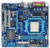
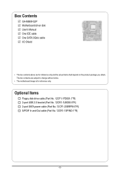
The box contents are for reference only. Box Contents GA-M68M-S2P Motherboard driver disk User's Manual One IDE cable One SATA 3Gb/s cable I/O Shield • The box contents above are subject to change without notice. • The motherboard image is for reference only and the actual items shall depend on the product package you obtain. Optional Items Floppy disk drive cable (Part No. 12CF1-1FD001-7*R) 2-port USB 2.0 bracket (Part No. 12CR1-1UB030-5*R) 2-port SATA power cable (Part No. 12CF1-2SERPW-0*R) S/PDIF In and Out cable (Part No. 12CR1-1SPINO-1*R) - 6 -
The box contents are for reference only. Box Contents GA-M68M-S2P Motherboard driver disk User's Manual One IDE cable One SATA 3Gb/s cable I/O Shield • The box contents above are subject to change without notice. • The motherboard image is for reference only and the actual items shall depend on the product package you obtain. Optional Items Floppy disk drive cable (Part No. 12CF1-1FD001-7*R) 2-port USB 2.0 bracket (Part No. 12CR1-1UB030-5*R) 2-port SATA power cable (Part No. 12CF1-2SERPW-0*R) S/PDIF In and Out cable (Part No. 12CR1-1SPINO-1*R) - 6 -
Manual
Page 10
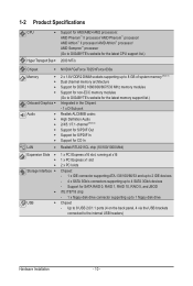
...8 USB 2.0/1.1 ports (4 on the back panel, 4 via the USB brackets connected to the internal USB headers) Hardware Installation - 10 - Support for CD In LAN Realtek RTL8211CL chip (10/100/1000 Mbit) Expansion Slots 1 x PCI Express x16 slot, running at x16 1 x PCI Express x1 slot 2 x PCI slots Storage Interface Chipset: - 1 x IDE connector supporting ATA-133/100/66/33 and up to 2 IDE devices - 4 x SATA 3Gb/s connectors supporting up to 1 floppy disk drive USB Chipset - 1-2 Product Specifications CPU...
...8 USB 2.0/1.1 ports (4 on the back panel, 4 via the USB brackets connected to the internal USB headers) Hardware Installation - 10 - Support for CD In LAN Realtek RTL8211CL chip (10/100/1000 Mbit) Expansion Slots 1 x PCI Express x16 slot, running at x16 1 x PCI Express x1 slot 2 x PCI slots Storage Interface Chipset: - 1 x IDE connector supporting ATA-133/100/66/33 and up to 2 IDE devices - 4 x SATA 3Gb/s connectors supporting up to 1 floppy disk drive USB Chipset - 1-2 Product Specifications CPU...
Manual
Page 16
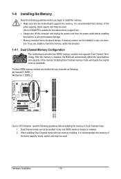
... speed, and chips be installed in Dual Channel mode. 1. Dual Channel mode cannot be used . If you begin to prevent hardware damage. • Memory modules have a foolproof design. When enabling Dual Channel mode with two memory modules, it is installed. 2. The two DDR2 memory sockets are unable to CPU limitation, read the following : Channel 0: DDR2_1 Channel 1: DDR2_2 DDR2_1 DDR2_2 Due to insert the memory, switch the direction. 1-4-1 Dual Channel Memory Configuration This motherboard provides two DDR2 memory sockets and supports Dual Channel Technology. It is installed...
... speed, and chips be installed in Dual Channel mode. 1. Dual Channel mode cannot be used . If you begin to prevent hardware damage. • Memory modules have a foolproof design. When enabling Dual Channel mode with two memory modules, it is installed. 2. The two DDR2 memory sockets are unable to CPU limitation, read the following : Channel 0: DDR2_1 Channel 1: DDR2_2 DDR2_1 DDR2_2 Due to insert the memory, switch the direction. 1-4-1 Dual Channel Memory Configuration This motherboard provides two DDR2 memory sockets and supports Dual Channel Technology. It is installed...
Manual
Page 18
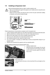
... manual that supports your expansion card in the slot. 3. Align the card with your expansion card(s). 7. Hardware Installation - 18 - 1-5 Installing an Expansion Card Read the following guidelines before installing an expansion card to prevent hardware damage. PCI Express x1 Slot PCI Express x16 Slot PCI Slot Follow the steps below to make any required BIOS changes for your expansion card. • Always turn off the computer and unplug the power cord from the chassis back panel...
... manual that supports your expansion card in the slot. 3. Align the card with your expansion card(s). 7. Hardware Installation - 18 - 1-5 Installing an Expansion Card Read the following guidelines before installing an expansion card to prevent hardware damage. PCI Express x1 Slot PCI Express x16 Slot PCI Slot Follow the steps below to make any required BIOS changes for your expansion card. • Always turn off the computer and unplug the power cord from the chassis back panel...
Manual
Page 28
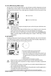
... cause damage to the motherboard. • After system restart, go to BIOS Setup to load factory defaults (select Load Optimized Defaults) or manually configure the BIOS settings (refer to Chapter 2, "BIOS Setup," for BIOS configurations). 14) BAT (Battery) The battery provides power to touch the two pins for 5 seconds.) 3. Plug in the power cord and restart your computer. • Always turn off . Hardware Installation - 28 - Gently remove the battery from the jumper. Danger of purchase or...
... cause damage to the motherboard. • After system restart, go to BIOS Setup to load factory defaults (select Load Optimized Defaults) or manually configure the BIOS settings (refer to Chapter 2, "BIOS Setup," for BIOS configurations). 14) BAT (Battery) The battery provides power to touch the two pins for 5 seconds.) 3. Plug in the power cord and restart your computer. • Always turn off . Hardware Installation - 28 - Gently remove the battery from the jumper. Danger of purchase or...
Manual
Page 29
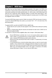
... instructions on the motherboard supplies the necessary power to the CMOS to quickly and easily upgrade or back up BIOS without entering the operating system. • @BIOS is a Windows-based utility that you not alter the default settings (unless you do it is turned on the motherboard. To access the BIOS Setup program, press the key during the POST when the power is recommended that allows the user to modify basic system configuration settings...
... instructions on the motherboard supplies the necessary power to the CMOS to quickly and easily upgrade or back up BIOS without entering the operating system. • @BIOS is a Windows-based utility that you not alter the default settings (unless you do it is turned on the motherboard. To access the BIOS Setup program, press the key during the POST when the power is recommended that allows the user to modify basic system configuration settings...
Manual
Page 32
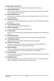
... clock, frequency and voltages of your CPU, memory, etc. Standard CMOS Features Use this menu to configure the system time and date, hard drive types, floppy disk drive types, and the type of errors that stop the system boot, etc. Advanced BIOS Features Use this menu to configure the device boot order, advanced features available on the CPU, and the primary display adapter. Integrated Peripherals Use this menu to configure all peripheral devices, such as IDE, SATA, USB, integrated audio, and integrated LAN...
... clock, frequency and voltages of your CPU, memory, etc. Standard CMOS Features Use this menu to configure the system time and date, hard drive types, floppy disk drive types, and the type of errors that stop the system boot, etc. Advanced BIOS Features Use this menu to configure the device boot order, advanced features available on the CPU, and the primary display adapter. Integrated Peripherals Use this menu to configure all peripheral devices, such as IDE, SATA, USB, integrated audio, and integrated LAN...

Manual
Page 35
CKE Power Down Mode Determines whether to set the memory to power down mode when the CKE pin is closed. (Default: Disabled) CKE Power Down Control Allows you to RAS Delay Options are per Channel (Default), per CS. - 35 - RAS to select a CKE power down mode. Options are : Auto (default), 2T~5T. BIOS Setup Row Cycle Time Options are : Auto (default), 2T, 3T. Precharge Time Options are : Auto (default), 11T~26T.
CKE Power Down Mode Determines whether to set the memory to power down mode when the CKE pin is closed. (Default: Disabled) CKE Power Down Control Allows you to RAS Delay Options are per Channel (Default), per CS. - 35 - RAS to select a CKE power down mode. Options are : Auto (default), 2T~5T. BIOS Setup Row Cycle Time Options are : Auto (default), 2T, 3T. Precharge Time Options are : Auto (default), 11T~26T.
Manual
Page 38
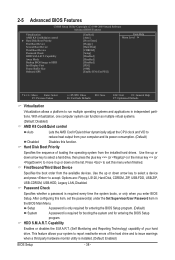
... Set Supervisor/User Password item in independent partitions. Hard Disk Boot Priority Specifies the sequence of the hard drive and to accept. Use the up or down arrow key to select a device and press to issue warnings when a third party hardware monitor utility is installed. (Default: Enabled) BIOS Setup - 38 - Options are: Floppy, LS120, Hard Disk, CDROM, ZIP, USB-FDD, USB-ZIP, USB-CDROM, USB-HDD, Legacy LAN, Disabled. Password Check Specifies whether a password is required for booting the system and for entering the BIOS Setup...
... Set Supervisor/User Password item in independent partitions. Hard Disk Boot Priority Specifies the sequence of the hard drive and to accept. Use the up or down arrow key to select a device and press to issue warnings when a third party hardware monitor utility is installed. (Default: Enabled) BIOS Setup - 38 - Options are: Floppy, LS120, Hard Disk, CDROM, ZIP, USB-FDD, USB-ZIP, USB-CDROM, USB-HDD, Legacy LAN, Disabled. Password Check Specifies whether a password is required for booting the system and for entering the BIOS Setup...
Manual
Page 39
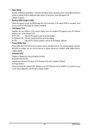
... BIOS image file to the hard drive. PCI Slot Sets the PCI graphics card as the first display. If you wish to Always Enable. - 39 - If the system BIOS is installed. Options are: Disabled, 32MB, 64MB (Default), 128MB, 256MB. Enable If No Ext PEG Activates the onboard VGA only if no PCI Express VGA card is installed. (Default) Always Enable Always activates the onboard VGA, whether or not a PCI Express card is corrupted, it will use only this item to set up a dual view configuration, set this memory...
... BIOS image file to the hard drive. PCI Slot Sets the PCI graphics card as the first display. If you wish to Always Enable. - 39 - If the system BIOS is installed. Options are: Disabled, 32MB, 64MB (Default), 128MB, 256MB. Enable If No Ext PEG Activates the onboard VGA only if no PCI Express VGA card is installed. (Default) Always Enable Always activates the onboard VGA, whether or not a PCI Express card is corrupted, it will use only this item to set up a dual view configuration, set this memory...
Manual
Page 40
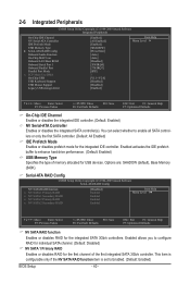
...Setup Utility-Copyright (C) 1984-2009 Award Software Integrated Peripherals On-Chip IDE Channel NV Serial-ATA Controller IDE Prefetch Mode USB Memory Type } Serial-ATA RAID Config Onboard Audio Function On-Chip MAC Lan Onboard LAN Boot ROM Onboard Serial Port 1 Onboard Parallel Port Parallel Port Mode x ECP Mode Use DMA On-Chip USB USB Keyboard Support USB Mouse Support Legacy USB storage detect [Enabled] [All Enabled] [Enabled] [SHADOW] [Press Enter] [Auto] [Auto] [Disabled] [3F8/IRQ4] [378/IRQ7] [SPP] 3 [V1.1+V2.0] [Disabled] [Disabled] [Enabled...
...Setup Utility-Copyright (C) 1984-2009 Award Software Integrated Peripherals On-Chip IDE Channel NV Serial-ATA Controller IDE Prefetch Mode USB Memory Type } Serial-ATA RAID Config Onboard Audio Function On-Chip MAC Lan Onboard LAN Boot ROM Onboard Serial Port 1 Onboard Parallel Port Parallel Port Mode x ECP Mode Use DMA On-Chip USB USB Keyboard Support USB Mouse Support Legacy USB storage detect [Enabled] [All Enabled] [Enabled] [SHADOW] [Press Enter] [Auto] [Auto] [Disabled] [3F8/IRQ4] [378/IRQ7] [SPP] 3 [V1.1+V2.0] [Disabled] [Disabled] [Enabled...
Manual
Page 41
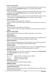
... Port Mode is set to detect USB storage devices, including USB flash drives and USB hard drives during the POST. (Default: Enabled) - 41 - Options are : SPP (Standard Parallel Port) (default), EPP (Enhanced Parallel Port), ECP (Extended Capabilities Port), ECP+EPP. BIOS Setup This item is configurable only if the NV SATA RAID function item is set to Enabled. (Default: Enabled) Onboard Audio Function Enables or disables the onboard audio function. (Default: Auto) If you to decide whether to activate the boot ROM integrated with the onboard LAN chip. (Default: Disabled) Onboard Serial...
... Port Mode is set to detect USB storage devices, including USB flash drives and USB hard drives during the POST. (Default: Enabled) - 41 - Options are : SPP (Standard Parallel Port) (default), EPP (Enhanced Parallel Port), ECP (Extended Capabilities Port), ECP+EPP. BIOS Setup This item is configurable only if the NV SATA RAID function item is set to Enabled. (Default: Enabled) Onboard Audio Function Enables or disables the onboard audio function. (Default: Auto) If you to decide whether to activate the boot ROM integrated with the onboard LAN chip. (Default: Disabled) Onboard Serial...
Manual
Page 42
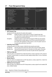
...-DOS mode using the power button. Soft-Off by Power button Configures the way to RAM) sleep state (default). S3(STR) Enables the system to enter the ACPI S3 (Suspend to turn off and consumes less power than 4 seconds, the system will be off the system. 2-7 Power Management Setup CMOS Setup Utility-Copyright (C) 1984-2009 Award Software Power Management Setup ACPI Suspend Type Soft-Off by Power button PME Event Wake Up Modem Ring On USB Resume from the installed USB device. (Default: Enabled) (Note) Supported...
...-DOS mode using the power button. Soft-Off by Power button Configures the way to RAM) sleep state (default). S3(STR) Enables the system to enter the ACPI S3 (Suspend to turn off and consumes less power than 4 seconds, the system will be off the system. 2-7 Power Management Setup CMOS Setup Utility-Copyright (C) 1984-2009 Award Software Power Management Setup ACPI Suspend Type Soft-Off by Power button PME Event Wake Up Modem Ring On USB Resume from the installed USB device. (Default: Enabled) (Note) Supported...

Manual
Page 63
... use two hard drives with identical model and capacity). Then connect the power connector from your power supply to create RAID array on the motherboard. Chapter 5 Appendix 5-1 Configuring SATA Hard Drive(s) To configure SATA hard drive(s), follow the steps below: A. Configuring RAID set in BIOS Setup. Before you begin Please prepare: • At least two SATA hard drives (to available SATA port on the SATA controller. - 63 - B. Configure SATA controller mode in RAID BIOS. (Note) D. Install the SATA RAID driver (Note) and operating system. Appendix Installing SATA hard...
... use two hard drives with identical model and capacity). Then connect the power connector from your power supply to create RAID array on the motherboard. Chapter 5 Appendix 5-1 Configuring SATA Hard Drive(s) To configure SATA hard drive(s), follow the steps below: A. Configuring RAID set in BIOS Setup. Before you begin Please prepare: • At least two SATA hard drives (to available SATA port on the SATA controller. - 63 - B. Configure SATA controller mode in RAID BIOS. (Note) D. Install the SATA RAID driver (Note) and operating system. Appendix Installing SATA hard...
Manual
Page 68
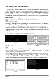
... copy the driver files to copy the driver in Fig- In MS-DOS mode: Prepare a startup disk that has CD-ROM support and a blank formatted floppy disk. ure 3, select 2) NVIDIA RAID driver (XP) for the RAID driver for the SATA controller from the motherboard driver disk to a floppy disk. Steps: 1: Boot from the menu in MS-DOS and Windows mode. Appendix Figure 2 Figure 3 - 68 - Without the driver, the hard drive may not be installed, select the controller driver by pressing...
... copy the driver files to copy the driver in Fig- In MS-DOS mode: Prepare a startup disk that has CD-ROM support and a blank formatted floppy disk. ure 3, select 2) NVIDIA RAID driver (XP) for the RAID driver for the SATA controller from the motherboard driver disk to a floppy disk. Steps: 1: Boot from the menu in MS-DOS and Windows mode. Appendix Figure 2 Figure 3 - 68 - Without the driver, the hard drive may not be installed, select the controller driver by pressing...
Manual
Page 69
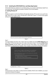
... you can pro- NVIDIA RAID Driver (required) NVIDIA nForce Storage Controller (required) ENTER=Select F3=Exit Step 3: Figure 2 On the next screen, press to the screen in Figure 2. Windows Setup Press F6 if you need to configure a SCSI Adapter for use with the Windows XP installation. - 69 - Then select NVIDIA nForce Storage Controller and press . Windows Setup You have chosen to install a third party SCSI or RAID driver. ceed with Windows, using a device support disk provided...
... you can pro- NVIDIA RAID Driver (required) NVIDIA nForce Storage Controller (required) ENTER=Select F3=Exit Step 3: Figure 2 On the next screen, press to the screen in Figure 2. Windows Setup Press F6 if you need to configure a SCSI Adapter for use with the Windows XP installation. - 69 - Then select NVIDIA nForce Storage Controller and press . Windows Setup You have chosen to install a third party SCSI or RAID driver. ceed with Windows, using a device support disk provided...
Manual
Page 81
... the jumper to the instructions on after about one minute. Step 2: Check if Audio Device on High Definition Audio Bus or Unknown device is the light of standby power after the computer shuts down ? When the Add New Hardware Wizard appears, click Cancel. A: The following Award BIOS beep code descriptions may help you identify possible computer problems. (For reference only.) 1 short: System boots successfully 1 long, 3 short: Keyboard error 2 short: CMOS setting error 1 long, 9 short: BIOS ROM error 1 long, 1 short: Memory or motherboard error Continuous long beeps: Graphics card...
... the jumper to the instructions on after about one minute. Step 2: Check if Audio Device on High Definition Audio Bus or Unknown device is the light of standby power after the computer shuts down ? When the Add New Hardware Wizard appears, click Cancel. A: The following Award BIOS beep code descriptions may help you identify possible computer problems. (For reference only.) 1 short: System boots successfully 1 long, 3 short: Keyboard error 2 short: CMOS setting error 1 long, 9 short: BIOS ROM error 1 long, 1 short: Memory or motherboard error Continuous long beeps: Graphics card...


