Manual
Page 4
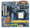
...GA-M61SME-S2 Motherboard Layout 7 Block Diagram ...8 Chapter 1 Hardware Installation 9 1-1 Considerations Prior to Installation 9 1-2 Feature Summary 10 1-3 Installation of the CPU and CPU Cooler 12 1-3-1 Installation of the CPU 12 1-3-2 Installation of the CPU Cooler 13 1-4 Installation of Memory 14 1-5 Installation of Expansion Cards 15 1-6 I/O Back Panel Introduction 17 1-7 Connectors Introduction 18 Chapter 2 BIOS... Setup 29 The Main Menu (For example: BIOS Ver. : E7 30 2-1 Standard CMOS Features 32 2-2 Advanced BIOS Features 34 2-3 ...
...GA-M61SME-S2 Motherboard Layout 7 Block Diagram ...8 Chapter 1 Hardware Installation 9 1-1 Considerations Prior to Installation 9 1-2 Feature Summary 10 1-3 Installation of the CPU and CPU Cooler 12 1-3-1 Installation of the CPU 12 1-3-2 Installation of the CPU Cooler 13 1-4 Installation of Memory 14 1-5 Installation of Expansion Cards 15 1-6 I/O Back Panel Introduction 17 1-7 Connectors Introduction 18 Chapter 2 BIOS... Setup 29 The Main Menu (For example: BIOS Ver. : E7 30 2-1 Standard CMOS Features 32 2-2 Advanced BIOS Features 34 2-3 ...

Manual
Page 5
Channel Audio Introduction 68 4-2 Troubleshooting 74 4-2-1 Frequently Asked Questions 74 4-2-2 Troubleshooting Procedure 75 Regulatory Statements 77 - 5 - Chapter 3 Drivers Installation 47 3-1 Install Chipset Drivers 47 3-2 SoftwareApplications 48 3-3 Driver CD Information 48 3-4 Hardware Information 49 3-5 Contact Us ...49 Chapter 4 Appendix 51 4-1 Unique Software Utilities 51 4-1-1 EasyTune 5 Introduction 51 4-1-2 Xpress Recovery2 Introduction 52 4-1-3 Flash BIOS Method Introduction 54 4-1-4 Configuring SATA Hard Drive(s 58 4-1-5 2- / 4- / 6- / 8-
Channel Audio Introduction 68 4-2 Troubleshooting 74 4-2-1 Frequently Asked Questions 74 4-2-2 Troubleshooting Procedure 75 Regulatory Statements 77 - 5 - Chapter 3 Drivers Installation 47 3-1 Install Chipset Drivers 47 3-2 SoftwareApplications 48 3-3 Driver CD Information 48 3-4 Hardware Information 49 3-5 Contact Us ...49 Chapter 4 Appendix 51 4-1 Unique Software Utilities 51 4-1-1 EasyTune 5 Introduction 51 4-1-2 Xpress Recovery2 Introduction 52 4-1-3 Flash BIOS Method Introduction 54 4-1-4 Configuring SATA Hard Drive(s 58 4-1-5 2- / 4- / 6- / 8-
Manual
Page 11
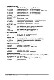
... fan failure warning Š Supports CPU Smart Fan function (Note 4) BIOS Š 1 4 Mbit flash ROM Š Use of licensed AWARD BIOS Š PnP 1.0a, DMI 2.0, SM BIOS 2.3, ACPI 1.0b Additional Features Š Supports @BIOS Š Supports Download Center Š Supports Q-Flash Š Supports EasyTune... is supported will depend on different motherboards. - 11 - Windows 64-bit operating system doesn't have such limitation. (Note 3) The GA-M61SME-S2 supports up an 8 channel audio configuration, you install. (Note 5) EasyTune functions may vary depending on the CPU you must use ...
... fan failure warning Š Supports CPU Smart Fan function (Note 4) BIOS Š 1 4 Mbit flash ROM Š Use of licensed AWARD BIOS Š PnP 1.0a, DMI 2.0, SM BIOS 2.3, ACPI 1.0b Additional Features Š Supports @BIOS Š Supports Download Center Š Supports Q-Flash Š Supports EasyTune... is supported will depend on different motherboards. - 11 - Windows 64-bit operating system doesn't have such limitation. (Note 3) The GA-M61SME-S2 supports up an 8 channel audio configuration, you install. (Note 5) EasyTune functions may vary depending on the CPU you must use ...

Manual
Page 14
... sure that they can be installed in only one direction. The motherboard supports DDRII memory modules, whereby BIOS will automatically detect memory capacity and specifications. Insert the DIMM memory module vertically into the DIMM socket. GA-M61SME-S2 Motherboard - 14 - Memory modules have a foolproof insertion design. A memory module can be used. 2. If you wish...
... sure that they can be installed in only one direction. The motherboard supports DDRII memory modules, whereby BIOS will automatically detect memory capacity and specifications. Insert the DIMM memory module vertically into the DIMM socket. GA-M61SME-S2 Motherboard - 14 - Memory modules have a foolproof insertion design. A memory module can be used. 2. If you wish...
Manual
Page 15
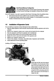
... Replace the screw to the onboard PCI Express x16 slot and press firmly down on the computer, if necessary, setup BIOS utility of expansion card from BIOS. 8. Press the expansion card firmly into the computer. 2. Replace your expansion card by the latch at the end of...of the expansion card. 6. Install related driver from the computer. 3. Hardware Installation Power on the slot. Dual Channel Memory Configuration The GA-M61SME-S2 supports the Dual Channel Technology. When you wish to release the card. Please align the VGA card to secure the slot bracket of Expansion...
... Replace the screw to the onboard PCI Express x16 slot and press firmly down on the computer, if necessary, setup BIOS utility of expansion card from BIOS. 8. Press the expansion card firmly into the computer. 2. Replace your expansion card by the latch at the end of...of the expansion card. 6. Install related driver from the computer. 3. Hardware Installation Power on the slot. Dual Channel Memory Configuration The GA-M61SME-S2 supports the Dual Channel Technology. When you wish to release the card. Please align the VGA card to secure the slot bracket of Expansion...
Manual
Page 21
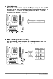
... provide up to locate pin 1 of floppy disk drives supported are: 360 KB, 720 KB, 1.2 MB, 1.44 MB, and 2.88 MB. Please refer to the BIOS setting for the SATA 3Gb/s and install the proper driver in order to connect a floppy disk drive. The types of the connector and the floppy...
... provide up to locate pin 1 of floppy disk drives supported are: 360 KB, 720 KB, 1.2 MB, 1.44 MB, and 2.88 MB. Please refer to the BIOS setting for the SATA 3Gb/s and install the proper driver in order to connect a floppy disk drive. The types of the connector and the floppy...

Manual
Page 26
... the COMB cable. Please contact your system to detect if the chassis cover is removed. Pin No. You can check the "Case Opened" status in BIOS Setup. Definition 1 1 Signal 2 GND GA-M61SME-S2 Motherboard - 26 - 15) COMB (COMB Connector) Be careful with the polarity of the COMB connector. Pin No.
... the COMB cable. Please contact your system to detect if the chassis cover is removed. Pin No. You can check the "Case Opened" status in BIOS Setup. Definition 1 1 Signal 2 GND GA-M61SME-S2 Motherboard - 26 - 15) COMB (COMB Connector) Be careful with the polarity of the COMB connector. Pin No.

Manual
Page 29
... take you wish to upgrade to the CMOS SETUP screen. If you to a new BIOS, either Gigabyte's Q-Flash or @BIOS utility can enter the BIOS setup screen by pressing "Ctrl + F1". Chapter 2 BIOS Setup BIOS (Basic Input and Output System) includes a CMOS SETUP utility which allows user to configure..., only for Main Menu Main Menu The on the motherboard supplies the necessary power to DOS before upgrading BIOS but directly download and update BIOS from BIOS default table Load the Optimized Defaults Q-Flash utility System Information Save all the CMOS changes, only for Option...
... take you wish to upgrade to the CMOS SETUP screen. If you to a new BIOS, either Gigabyte's Q-Flash or @BIOS utility can enter the BIOS setup screen by pressing "Ctrl + F1". Chapter 2 BIOS Setup BIOS (Basic Input and Output System) includes a CMOS SETUP utility which allows user to configure..., only for Main Menu Main Menu The on the motherboard supplies the necessary power to DOS before upgrading BIOS but directly download and update BIOS from BIOS default table Load the Optimized Defaults Q-Flash utility System Information Save all the CMOS changes, only for Option...

Manual
Page 30
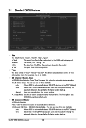
...from the exact settings for stability. 3. CMOS Setup Utility-Copyright (C) 1984-2007 Award Software ` Standard CMOS Features ` Advanced BIOS Features ` Integrated Peripherals ` Power Management Setup ` PnP/PCI Configurations ` PC Health Status Load Fail-Safe Defaults Load Optimized Defaults... don't find the settings you enter Award BIOS CMOS Setup Utility, the Main Menu (as usual. Award Modular BIOS v6.00PG, An Energy Star Ally Copyright (C) 1984-2007, Award Software, Inc. GA-M61SME-S2 Motherboard - 30 - GA-M61SME-S2 E7 . . . . :BIOS Setup/Q-Flash :Xpress Recovery2 :Boot Menu :...
...from the exact settings for stability. 3. CMOS Setup Utility-Copyright (C) 1984-2007 Award Software ` Standard CMOS Features ` Advanced BIOS Features ` Integrated Peripherals ` Power Management Setup ` PnP/PCI Configurations ` PC Health Status Load Fail-Safe Defaults Load Optimized Defaults... don't find the settings you enter Award BIOS CMOS Setup Utility, the Main Menu (as usual. Award Modular BIOS v6.00PG, An Energy Star Ally Copyright (C) 1984-2007, Award Software, Inc. GA-M61SME-S2 Motherboard - 30 - GA-M61SME-S2 E7 . . . . :BIOS Setup/Q-Flash :Xpress Recovery2 :Boot Menu :...

Manual
Page 31
... Setup. „ Set User Password Change, set , or disable password. „ Standard CMOS Features This setup page includes all the items in standard compatible BIOS. „ Advanced BIOS Features This setup page includes all the items of Award special enhanced features. „ Integrated Peripherals This setup page includes all onboard peripherals. „... Optimized Defaults indicates the value of Green function features. „ PnP/PCI Configuration This setup page includes all CMOS value changes and exit setup. - 31 - BIOS Setup
... Setup. „ Set User Password Change, set , or disable password. „ Standard CMOS Features This setup page includes all the items in standard compatible BIOS. „ Advanced BIOS Features This setup page includes all the items of Award special enhanced features. „ Integrated Peripherals This setup page includes all onboard peripherals. „... Optimized Defaults indicates the value of Green function features. „ PnP/PCI Configuration This setup page includes all CMOS value changes and exit setup. - 31 - BIOS Setup
Manual
Page 32
... Sat, determined by the BIOS and is 13:0:0. IDE Channel 0 Master, Slave IDE HDD Auto-Detection Press "Enter" to 31 (or the maximum allowed in . IDE Device Setup. You can manually input the correct settings Access Mode Use this option for automatic device detection. IDE/SATA Device Setup. GA-M61SME-S2 Motherboard - 32 - For...
... Sat, determined by the BIOS and is 13:0:0. IDE Channel 0 Master, Slave IDE HDD Auto-Detection Press "Enter" to 31 (or the maximum allowed in . IDE Device Setup. You can manually input the correct settings Access Mode Use this option for automatic device detection. IDE/SATA Device Setup. GA-M61SME-S2 Motherboard - 32 - For...

Manual
Page 33
... stop if an error is 3 mode Floppy Drive. Base Memory The POST of base (or conventional) memory installed in the computer. Whenever the BIOS detects a non-fatal error the system will not stop for all other errors. (Default value) All, But Diskette The system boot will determine... prompted. Floppy 3 Mode Support (for a keyboard or disk error; Enter the appropriate option based on the outside drive casing. Extended Memory The BIOS determines how much extended memory is present during power up. All, But Keyboard The system boot will be labeled on this to set the access...
... stop if an error is 3 mode Floppy Drive. Base Memory The POST of base (or conventional) memory installed in the computer. Whenever the BIOS detects a non-fatal error the system will not stop for all other errors. (Default value) All, But Diskette The system boot will determine... prompted. Floppy 3 Mode Support (for a keyboard or disk error; Enter the appropriate option based on the outside drive casing. Extended Memory The BIOS determines how much extended memory is present during power up. All, But Keyboard The system boot will be labeled on this to set the access...
Manual
Page 34
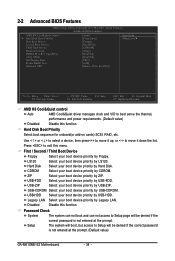
... access to Setup will be denied if the correct password is not entered at the prompt. (Default value) GA-M61SME-S2 Motherboard - 34 - 2-2 Advanced BIOS Features CMOS Setup Utility-Copyright (C) 1984-2007 Award Software Advanced BIOS Features AMD K8 Cool&Quiet control ` Hard Disk Boot Priority First Boot Device Second Boot Device Third Boot Device...
... access to Setup will be denied if the correct password is not entered at the prompt. (Default value) GA-M61SME-S2 Motherboard - 34 - 2-2 Advanced BIOS Features CMOS Setup Utility-Copyright (C) 1984-2007 Award Software Advanced BIOS Features AMD K8 Cool&Quiet control ` Hard Disk Boot Priority First Boot Device Second Boot Device Third Boot Device...

Manual
Page 35
Enabled Enable HDD S.M.A.R.T. capability. Disabled Disable HDD S.M.A.R.T. PCI Slot PEG Set Init display first to 256 M. Set frame buffer size to PCI. BIOS Setup Enable If No Ext PEG Activate the onboard VGA only when no PCI Express VGA card is installed. (Default value) Always Enable Always activate ...
Enabled Enable HDD S.M.A.R.T. capability. Disabled Disable HDD S.M.A.R.T. PCI Slot PEG Set Init display first to 256 M. Set frame buffer size to PCI. BIOS Setup Enable If No Ext PEG Activate the onboard VGA only when no PCI Express VGA card is installed. (Default value) Always Enable Always activate ...
Manual
Page 37
...to base memory(640 K). Enable onboard Serial port 1 and address is 3E8/IRQ4. Disable this function. Disabled Disable this function. BIOS Setup Onboard LAN Boot ROM This function decide whether to invoke the boot ROM of the onboard LAN chip. Disabled Disable NV .... Onboard Audio Function Auto Auto-detect onboard audio function. (Default value) Disabled Disable this function. (Default value) Onboard Serial Port 1 Auto BIOS will automatically setup the Serial port 1 address. 3F8/IRQ4 Enable onboard Serial port 1 and address is 3F8/IRQ4. (Default value) 2F8/IRQ3...
...to base memory(640 K). Enable onboard Serial port 1 and address is 3E8/IRQ4. Disable this function. Disabled Disable this function. BIOS Setup Onboard LAN Boot ROM This function decide whether to invoke the boot ROM of the onboard LAN chip. Disabled Disable NV .... Onboard Audio Function Auto Auto-detect onboard audio function. (Default value) Disabled Disable this function. (Default value) Onboard Serial Port 1 Auto BIOS will automatically setup the Serial port 1 address. 3F8/IRQ4 Enable onboard Serial port 1 and address is 3F8/IRQ4. (Default value) 2F8/IRQ3...
Manual
Page 38
.... Enable onboard LPT port and address is 2E8/IRQ3. Disabled Disable USB keyboard support. (Default value) USB Mouse Support Enabled Enable USB mouse support. GA-M61SME-S2 Motherboard - 38 - ECP Mode Use DMA 3 Set ECP Mode Use DMA to 3. (Default value) 1 Set ECP Mode Use DMA to detect USB... storage devices, including USB flash drives and USB hard drives during POST. Enabled BIOS will automatically setup the port 2 address. 3F8/IRQ4 2F8/IRQ3 Enable onboard Serial port 2 and address is 3F8/IRQ4. Onboard Serial Port 2 Auto...
.... Enable onboard LPT port and address is 2E8/IRQ3. Disabled Disable USB keyboard support. (Default value) USB Mouse Support Enabled Enable USB mouse support. GA-M61SME-S2 Motherboard - 38 - ECP Mode Use DMA 3 Set ECP Mode Use DMA to 3. (Default value) 1 Set ECP Mode Use DMA to detect USB... storage devices, including USB flash drives and USB hard drives during POST. Enabled BIOS will automatically setup the port 2 address. 3F8/IRQ4 2F8/IRQ3 Enable onboard Serial port 2 and address is 3F8/IRQ4. Onboard Serial Port 2 Auto...

Manual
Page 39
... if button is pressed less than 4 seconds. PME Event Wake Up This feature requires an ATX power supply that provides at least 1A on function. BIOS Setup Disabled Enabled Disable this function. Enable PME as wake up system from suspend mode. (Default value) (Note) Supported on function. (Default value) USB Resume...
... if button is pressed less than 4 seconds. PME Event Wake Up This feature requires an ATX power supply that provides at least 1A on function. BIOS Setup Disabled Enabled Disable this function. Enable PME as wake up system from suspend mode. (Default value) (Note) Supported on function. (Default value) USB Resume...

Manual
Page 41
BIOS Setup 2-5 PnP/PCI Configurations CMOS Setup Utility-Copyright (C) 1984-2007 Award Software PnP/PCI Configurations PCI 1 IRQ Assignment PCI 2 IRQ Assignment [Auto] [Auto] Item Help ...
BIOS Setup 2-5 PnP/PCI Configurations CMOS Setup Utility-Copyright (C) 1984-2007 Award Software PnP/PCI Configurations PCI 1 IRQ Assignment PCI 2 IRQ Assignment [Auto] [Auto] Item Help ...

Manual
Page 43
Auto BIOS autodetects the type of CPU fan you installed and sets the optimal CPU Smart FAN control mode for it. (Default value) Voltage Set to PWM ... with Easy Tune based on their requirements. (Default value) CPU Smart FAN Mode This option is available only when CPU Smart FAN Control is enabled. BIOS Setup When this function.
Auto BIOS autodetects the type of CPU fan you installed and sets the optimal CPU Smart FAN control mode for it. (Default value) Voltage Set to PWM ... with Easy Tune based on their requirements. (Default value) CPU Smart FAN Mode This option is available only when CPU Smart FAN Control is enabled. BIOS Setup When this function.

Manual
Page 44
...system parameters that allow minimum system performance. 2-8 Load Optimized Defaults CMOS Setup Utility-Copyright (C) 1984-2007 Award Software ` Standard CMOS Features ` Advanced BIOS Features ` Integrated Peripherals ` Power Management Setup ` PnP/PCI Configurations ` PC Health Status Load Fail-Safe Defaults Load Optimized Defaults Set Supervisor Password Set... F8: Q-Flash KLJI: Select Item F10: Save & Exit Setup Load Optimized Defaults Selecting this field loads the factory defaults for BIOS and Chipset Features which the system automatically detects. GA-M61SME-S2 Motherboard - 44 -
...system parameters that allow minimum system performance. 2-8 Load Optimized Defaults CMOS Setup Utility-Copyright (C) 1984-2007 Award Software ` Standard CMOS Features ` Advanced BIOS Features ` Integrated Peripherals ` Power Management Setup ` PnP/PCI Configurations ` PC Health Status Load Fail-Safe Defaults Load Optimized Defaults Set Supervisor Password Set... F8: Q-Flash KLJI: Select Item F10: Save & Exit Setup Load Optimized Defaults Selecting this field loads the factory defaults for BIOS and Chipset Features which the system automatically detects. GA-M61SME-S2 Motherboard - 44 -


