Manual
Page 10
... Supports High Definition Audio Š Supports 2 / 4 / 6 / 8 channel audio (Note 1) Š Supports S/PDIF In/Out connection Š Supports CD In connection Storage Š nVIDIA® GeForce 6100/nForce 405 chipset - 1 FDD connector, allowing connection of 1 FDD device - 1 IDE connector with ATA-33/66/100/133 support, allowing connection of 2 IDE devices - 2 SATA 3Gb/s connectors, allowing connection of 2 SATA 3Gb/s devices - 1-2 Feature Summary CPU Š Socket AM2 for additional 4 USB 2.0/1.1 ports by cables Š 1 Chassis Intrusion connector GA-M61SME-S2 Motherboard...
... Supports High Definition Audio Š Supports 2 / 4 / 6 / 8 channel audio (Note 1) Š Supports S/PDIF In/Out connection Š Supports CD In connection Storage Š nVIDIA® GeForce 6100/nForce 405 chipset - 1 FDD connector, allowing connection of 1 FDD device - 1 IDE connector with ATA-33/66/100/133 support, allowing connection of 2 IDE devices - 2 SATA 3Gb/s connectors, allowing connection of 2 SATA 3Gb/s devices - 1-2 Feature Summary CPU Š Socket AM2 for additional 4 USB 2.0/1.1 ports by cables Š 1 Chassis Intrusion connector GA-M61SME-S2 Motherboard...
Manual
Page 11
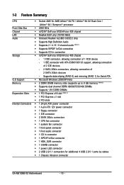
...Rear Panel I/O Š 1 PS/2 keyboard port Š 1 PS/2 mouse port Š 1 parallel port Š 1 COMA port Š 1 VGA port Š 4 USB 2.0/1.1 ports Š 1 RJ-45 port Š 3 audio jacks (Line In / Line Out / MIC In) I/O Control Š IT8716 chip Hardware Monitor Š System voltage detection Š CPU / System temperature detection Š CPU / System fan speed detection Š CPU / System warning temperature Š CPU / System fan failure warning Š Supports CPU Smart Fan function (Note 4) BIOS Š 1 4 Mbit flash ROM Š Use of licensed AWARD BIOS...
...Rear Panel I/O Š 1 PS/2 keyboard port Š 1 PS/2 mouse port Š 1 parallel port Š 1 COMA port Š 1 VGA port Š 4 USB 2.0/1.1 ports Š 1 RJ-45 port Š 3 audio jacks (Line In / Line Out / MIC In) I/O Control Š IT8716 chip Hardware Monitor Š System voltage detection Š CPU / System temperature detection Š CPU / System fan speed detection Š CPU / System warning temperature Š CPU / System fan failure warning Š Supports CPU Smart Fan function (Note 4) BIOS Š 1 4 Mbit flash ROM Š Use of licensed AWARD BIOS...
Manual
Page 15
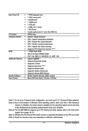
... down on the card are indeed seated in motherboard. 4. Press the expansion card firmly into the computer. 2. Replace your computer's chassis cover, screws and slot bracket from the operating system. Remove your computer's chassis cover. 7. Installing a PCI Express x16 expansion card: - 15 - Power on the computer, if necessary, setup BIOS utility of Expansion Cards You can install your VGA card is locked by following the steps outlined below : 1. Dual Channel Memory Configuration The GA-M61SME-S2 supports the Dual Channel Technology.
... down on the card are indeed seated in motherboard. 4. Press the expansion card firmly into the computer. 2. Replace your computer's chassis cover, screws and slot bracket from the operating system. Remove your computer's chassis cover. 7. Installing a PCI Express x16 expansion card: - 15 - Power on the computer, if necessary, setup BIOS utility of Expansion Cards You can install your VGA card is locked by following the steps outlined below : 1. Dual Channel Memory Configuration The GA-M61SME-S2 supports the Dual Channel Technology.
Manual
Page 20
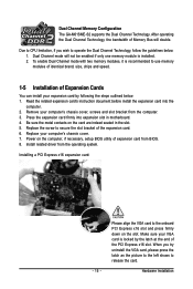
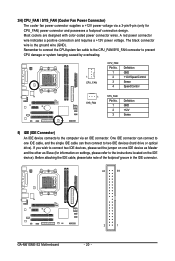
... connect two IDE devices, please set the jumper on the IDE device). The black connector wire is the ground wire (GND). One IDE connector can connect to two IDE devices (hard drive or optical drive). Before attaching the IDE cable, please take note of the foolproof groove in the IDE connector. 40 39 GA-M61SME-S2 Motherboard 2 1 - 20 - 3/4) CPU_FAN / SYS_FAN (Cooler Fan Power Connector) The cooler fan power connector supplies a +12V power voltage via an IDE connector. Most coolers are designed with color-coded power connector wires. Remember to connect the CPU/system fan cable...
... connect two IDE devices, please set the jumper on the IDE device). The black connector wire is the ground wire (GND). One IDE connector can connect to two IDE devices (hard drive or optical drive). Before attaching the IDE cable, please take note of the foolproof groove in the IDE connector. 40 39 GA-M61SME-S2 Motherboard 2 1 - 20 - 3/4) CPU_FAN / SYS_FAN (Cooler Fan Power Connector) The cooler fan power connector supplies a +12V power voltage via an IDE connector. Most coolers are designed with color-coded power connector wires. Remember to connect the CPU/system fan cable...
Manual
Page 21
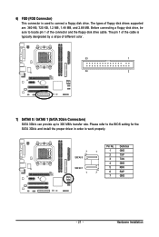
... the BIOS setting for the SATA 3Gb/s and install the proper driver in order to locate pin 1 of the connector and the floppy disk drive cable. Before connecting a floppy disk drive, be sure to work properly. 7 1 SATAII 0 SATAII 1 1 7 Pin No. 1 2 3 4 5 6 7 Definition GND TXP TXN GND RXN RXP GND - 21 - The types of different color. 33 1 34 2 7) SATAII 0 / SATAII 1 (SATA 3Gb/s Connectors) SATA 3Gb/s can provide up to connect a floppy disk drive. The pin 1 of the cable is used to...
... the BIOS setting for the SATA 3Gb/s and install the proper driver in order to locate pin 1 of the connector and the floppy disk drive cable. Before connecting a floppy disk drive, be sure to work properly. 7 1 SATAII 0 SATAII 1 1 7 Pin No. 1 2 3 4 5 6 7 Definition GND TXP TXN GND RXN RXP GND - 21 - The types of different color. 33 1 34 2 7) SATAII 0 / SATAII 1 (SATA 3Gb/s Connectors) SATA 3Gb/s can provide up to connect a floppy disk drive. The pin 1 of the cable is used to...
Manual
Page 22
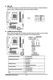
... (IDE Hard Disk Active LED) SPEAK (Speaker Connector) RES (Reset Switch) PW (Power Switch) MSG (Message LED/Power/Sleep LED) NC GA-M61SME-S2 Motherboard Reset Switch IDE Hard Disk Active LED Pin 1: LED anode(+) Pin 2: LED cathode(-) Pin 1: Power Pin 2- Message LED/ Power/ Sleep LED Speaker Connector Power Switch MSG+ MSG- PW+ PWSPEAK+ SPEAK- 2 20 1 19 HD+ HD- Definition 1 MPD+ 1 2 MPD- 3 MPD- 9) F_PANEL (Front Panel Jumper) Please connect the power LED, PC speaker, reset switch and power switch etc. It will blink when the system enters suspend mode(S1). Pin 3: NC Pin 4: Data...
... (IDE Hard Disk Active LED) SPEAK (Speaker Connector) RES (Reset Switch) PW (Power Switch) MSG (Message LED/Power/Sleep LED) NC GA-M61SME-S2 Motherboard Reset Switch IDE Hard Disk Active LED Pin 1: LED anode(+) Pin 2: LED cathode(-) Pin 1: Power Pin 2- Message LED/ Power/ Sleep LED Speaker Connector Power Switch MSG+ MSG- PW+ PWSPEAK+ SPEAK- 2 20 1 19 HD+ HD- Definition 1 MPD+ 1 2 MPD- 3 MPD- 9) F_PANEL (Front Panel Jumper) Please connect the power LED, PC speaker, reset switch and power switch etc. It will blink when the system enters suspend mode(S1). Pin 3: NC Pin 4: Data...

Manual
Page 30
... settings for onboard (or add-on the screen. Award Modular BIOS v6.00PG, An Energy Star Ally Copyright (C) 1984-2007, Award Software, Inc. Use arrow keys to select among the items and press to access advanced options. 2. GA-M61SME-S2 Motherboard - 30 - This action makes the system reset to accept . GA-M61SME-S2 E7 . . . . :BIOS Setup/Q-Flash :Xpress Recovery2 :Boot Menu :Qflash 01/23/2007-NV-MCP61-6A61KG05C-00 :Boot Menu Use < > or < > to select a device, then press enter...
... settings for onboard (or add-on the screen. Award Modular BIOS v6.00PG, An Energy Star Ally Copyright (C) 1984-2007, Award Software, Inc. Use arrow keys to select among the items and press to access advanced options. 2. GA-M61SME-S2 Motherboard - 30 - This action makes the system reset to accept . GA-M61SME-S2 E7 . . . . :BIOS Setup/Q-Flash :Xpress Recovery2 :Boot Menu :Qflash 01/23/2007-NV-MCP61-6A61KG05C-00 :Boot Menu Use < > or < > to select a device, then press enter...
Manual
Page 32
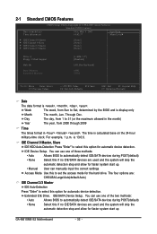
... example, 1 p.m. GA-M61SME-S2 Motherboard - 32 - IDE/SATA Device Setup. You can use one of three methods: • Auto • None Allows BIOS to select this option for the hard drive. You can manually input the correct settings Access Mode Use this if no IDE/SATA devices are used and the system will skip the automatic detection step and allow for automatic device detection. Extended IDE Drive. IDE Channel 0 Master, Slave IDE HDD Auto-Detection Press "Enter" to automatically detect IDE/SATA devices during POST(default) Select...
... example, 1 p.m. GA-M61SME-S2 Motherboard - 32 - IDE/SATA Device Setup. You can use one of three methods: • Auto • None Allows BIOS to select this option for the hard drive. You can manually input the correct settings Access Mode Use this if no IDE/SATA devices are used and the system will skip the automatic detection step and allow for automatic device detection. Extended IDE Drive. IDE Channel 0 Master, Slave IDE HDD Auto-Detection Press "Enter" to automatically detect IDE/SATA devices during POST(default) Select...
Manual
Page 37
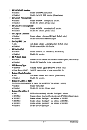
.... (Default value) Base Memory(640K) Set USB memory type to enhance HDD transfer speed. (Default value) Disabled Disable IDE data buffer for the system stability. Enabled Enable this function. Onboard Audio Function Auto Auto-detect onboard audio function. (Default value) Disabled Disable this function. Enable onboard Serial port 1 and address is 3E8/IRQ4. Disabled Disable this function. (Default value) NV SATA 1 Secondary RAID Enabled Disabled Enable NV SATA 1 secondary RAID function. Disabled Disable onboard Serial port 1. - 37 - Onboard LAN Boot ROM This...
.... (Default value) Base Memory(640K) Set USB memory type to enhance HDD transfer speed. (Default value) Disabled Disable IDE data buffer for the system stability. Enabled Enable this function. Onboard Audio Function Auto Auto-detect onboard audio function. (Default value) Disabled Disable this function. Enable onboard Serial port 1 and address is 3E8/IRQ4. Disabled Disable this function. (Default value) NV SATA 1 Secondary RAID Enabled Disabled Enable NV SATA 1 secondary RAID function. Disabled Disable onboard Serial port 1. - 37 - Onboard LAN Boot ROM This...
Manual
Page 38
... This option allows users to decide whether to 1. USB Keyboard Support Enabled Enable USB keyboard support. Disabled Disable USB keyboard support. (Default value) USB Mouse Support Enabled Enable USB mouse support. Enable onboard Serial port 2 and address is 2F8/IRQ3. (Default value) 3E8/IRQ4 2E8/IRQ3 Enable onboard Serial port 2 and address is 3F8/IRQ4. Parallel Port Mode SPP Using Parallel port as Standard Parallel Port. (Default value) EPP Using Parallel port as Extended Capabilities Port. On-Chip USB Disabled Disable this function. GA-M61SME-S2 Motherboard - 38...
... This option allows users to decide whether to 1. USB Keyboard Support Enabled Enable USB keyboard support. Disabled Disable USB keyboard support. (Default value) USB Mouse Support Enabled Enable USB mouse support. Enable onboard Serial port 2 and address is 2F8/IRQ3. (Default value) 3E8/IRQ4 2E8/IRQ3 Enable onboard Serial port 2 and address is 3F8/IRQ4. Parallel Port Mode SPP Using Parallel port as Standard Parallel Port. (Default value) EPP Using Parallel port as Extended Capabilities Port. On-Chip USB Disabled Disable this function. GA-M61SME-S2 Motherboard - 38...

Manual
Page 39
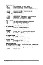
... an ATX power supply that provides at least 1A on function. Enable PME as wake up system from suspend mode. (Default value) (Note) Supported on function. (Default value) USB Resume from any suspend state. BIOS Setup Disabled Disable Modem Ring on the 5VSB lead. 2-4 Power Management Setup CMOS Setup Utility-Copyright (C) 1984-2007 Award Software Power Management Setup ACPI Suspend Type Soft-Off by Power button PME Event Wake Up Modem Ring On USB Resume from Suspend Power-On by Power button...
... an ATX power supply that provides at least 1A on function. Enable PME as wake up system from suspend mode. (Default value) (Note) Supported on function. (Default value) USB Resume from any suspend state. BIOS Setup Disabled Disable Modem Ring on the 5VSB lead. 2-4 Power Management Setup CMOS Setup Utility-Copyright (C) 1984-2007 Award Software Power Management Setup ACPI Suspend Type Soft-Off by Power button PME Event Wake Up Modem Ring On USB Resume from Suspend Power-On by Power button...
Manual
Page 45
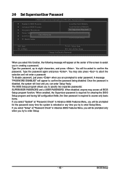
... to enter password. 2-9 Set Supervisor/User Password CMOS Setup Utility-Copyright (C) 1984-2007 Award Software ` Standard CMOS Features ` Advanced BIOS Features ` Integrated Peripherals ` Power Management Setup ` PnP/PCI ConfiguratioEnsnter Password: ` PC Health Status Load Fail-Safe Defaults Load Optimized Defaults Set Supervisor Password Set User Password Save & Exit Setup Exit Without Saving ESC: Quit F8: Q-Flash KLJI: Select Item F10: Save & Exit Setup Change/Set/Disable Password When you select this function, the following message will appear at the center of the screen to...
... to enter password. 2-9 Set Supervisor/User Password CMOS Setup Utility-Copyright (C) 1984-2007 Award Software ` Standard CMOS Features ` Advanced BIOS Features ` Integrated Peripherals ` Power Management Setup ` PnP/PCI ConfiguratioEnsnter Password: ` PC Health Status Load Fail-Safe Defaults Load Optimized Defaults Set Supervisor Password Set User Password Save & Exit Setup Exit Without Saving ESC: Quit F8: Q-Flash KLJI: Select Item F10: Save & Exit Setup Change/Set/Disable Password When you select this function, the following message will appear at the center of the screen to...
Manual
Page 52
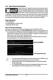
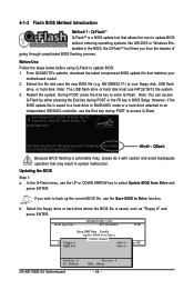
... CD-ROM drive. Boot from CD/DVD: Press any key to enter Xpress Recovery2. 4-1-2 Xpress Recovery2 Introduction Xpress Recovery2 is designed to provide quick backup and restoration of system memory 3. System storage capacity and the reading/writing speed of the hard disk will appear in the bottom left corner of OS and all required drivers as well as software. VESA-supported VGA cards How to use the...
... CD-ROM drive. Boot from CD/DVD: Press any key to enter Xpress Recovery2. 4-1-2 Xpress Recovery2 Introduction Xpress Recovery2 is designed to provide quick backup and restoration of system memory 3. System storage capacity and the reading/writing speed of the hard disk will appear in the bottom left corner of OS and all required drivers as well as software. VESA-supported VGA cards How to use the...
Manual
Page 54
... "Floppy A" and press ENTER. Extract the file and save the new BIOS file (e.g. M61SMES2.F1) to your motherboard model. 2. Updating the BIOS Step 1: a. In the Q-Flash menu, use the Save BIOS to Drive function. If you from Drive Sa0vefilBeI(Os)SfotounDdrive EnteFr l:oRppuyn A KL:Move ESC:Reset :Power Off HDD 0-0 Total size : 0 F5 : Refresh GA-M61SME-S2 Motherboard Free size : 0 DEL : Delete - 54 - b. Note: The USB flash drive or hard disk must use FAT32/16/12 file system. 3. GA-M61SME-S2 E7 . . . . :BIOS Setup/Q-Flash :Xpress Recovery2 :Boot Menu :Qflash...
... "Floppy A" and press ENTER. Extract the file and save the new BIOS file (e.g. M61SMES2.F1) to your motherboard model. 2. Updating the BIOS Step 1: a. In the Q-Flash menu, use the Save BIOS to Drive function. If you from Drive Sa0vefilBeI(Os)SfotounDdrive EnteFr l:oRppuyn A KL:Move ESC:Reset :Power Off HDD 0-0 Total size : 0 F5 : Refresh GA-M61SME-S2 Motherboard Free size : 0 DEL : Delete - 54 - b. Note: The USB flash drive or hard disk must use FAT32/16/12 file system. 3. GA-M61SME-S2 E7 . . . . :BIOS Setup/Q-Flash :Xpress Recovery2 :Boot Menu :Qflash...
Manual
Page 56
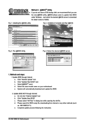
... as: M61SMES2.F1). GA-M61SME-S2 Motherboard - 56 - Installation Complete and Run @BIOS Select @BIOS item than click Install Fig 3. Methods and steps: I. The @BIOS Utility Click Start/ Programs/ GIGABYTE/@BIOS Fig 4. Select the exact model name on your motherboard e. e. System will automatically download and update the BIOS. Please select "All Files" in dialog box while opening the old file. II. Complete update process following the instruction. Method 2 : @BIOSTM Utility If you do...
... as: M61SMES2.F1). GA-M61SME-S2 Motherboard - 56 - Installation Complete and Run @BIOS Select @BIOS item than click Install Fig 3. Methods and steps: I. The @BIOS Utility Click Start/ Programs/ GIGABYTE/@BIOS Fig 4. Select the exact model name on your motherboard e. e. System will automatically download and update the BIOS. Please select "All Files" in dialog box while opening the old file. II. Complete update process following the instruction. Method 2 : @BIOSTM Utility If you do...
Manual
Page 59
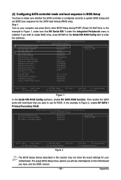
... enter BIOS Setup during POST (Power-On Self Test). In the example in Figure 1, make sure whether the SATA controller is enabled. CMOS Setup Utility-Copyright (C) 1984-2007 Award Software Integrated Peripherals ` Serial-ATA RAID Config On-Chip IDE Channel0 On-Chip MAC Lan NV Serial-ATA 1 IDE Prefetch Mode USB Memory Type Onboard Audio Function Onboard LAN Boot ROM Onboard Serial Port 1 Onboard Serial Port 2 Onboard Parallel Port Parallel Port Mode x ECP Mode Use DMA On-Chip USB USB Keyboard Support USB Mouse Support Legacy USB Storage detect [Press Enter] [Enabled] [Auto] [Enabled...
... enter BIOS Setup during POST (Power-On Self Test). In the example in Figure 1, make sure whether the SATA controller is enabled. CMOS Setup Utility-Copyright (C) 1984-2007 Award Software Integrated Peripherals ` Serial-ATA RAID Config On-Chip IDE Channel0 On-Chip MAC Lan NV Serial-ATA 1 IDE Prefetch Mode USB Memory Type Onboard Audio Function Onboard LAN Boot ROM Onboard Serial Port 1 Onboard Serial Port 2 Onboard Parallel Port Parallel Port Mode x ECP Mode Use DMA On-Chip USB USB Keyboard Support USB Mouse Support Legacy USB Storage detect [Press Enter] [Enabled] [Auto] [Enabled...
Manual
Page 64
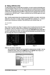
... MCP61 Series Raid (XP) if you wish to that has CD-ROM support and a blank formatted floppy disk. Boot from the menu. At the D:\> prompt, type the following two commands. Figure 10 Figure 11 (Note) For users without a startup disk: Use an alternative system and insert the GIGABYTE motherboard driver CD-ROM. Press 0 to a floppy disk. Once at the A:\> prompt, change to install the SATA RAID driver during the Windows setup process. From the CD-ROM drive...
... MCP61 Series Raid (XP) if you wish to that has CD-ROM support and a blank formatted floppy disk. Boot from the menu. At the D:\> prompt, type the following two commands. Figure 10 Figure 11 (Note) For users without a startup disk: Use an alternative system and insert the GIGABYTE motherboard driver CD-ROM. Press 0 to a floppy disk. Once at the A:\> prompt, change to install the SATA RAID driver during the Windows setup process. From the CD-ROM drive...
Manual
Page 65
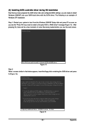
... mass storage devices(s) * To specify additional SCSI adapters, CD-ROM drives, or special disk controllers for use with Windows, including those for which you have a device support disk from a mass storage device manufacturer, press S. * If you do not want to specify additional mass storage devices for use with the SATA driver. Figure 13 Step 2: When a screen similar to that you have prepared the SATA driver disk and configured BIOS settings, you are ready to install Windows 2000...
... mass storage devices(s) * To specify additional SCSI adapters, CD-ROM drives, or special disk controllers for use with Windows, including those for which you have a device support disk from a mass storage device manufacturer, press S. * If you do not want to specify additional mass storage devices for use with the SATA driver. Figure 13 Step 2: When a screen similar to that you have prepared the SATA driver disk and configured BIOS settings, you are ready to install Windows 2000...
Manual
Page 67
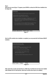
... continue the SATA driver installation from the floppy disk. To set up Windows XP now, press ENTER. To quit Setup without installing Windows XP, press F3. Step 4: When the next screen (Figure 17) appears, press ENTER to run on your computer. After that hard drive. Windows Setup Setup will not have to Setup. Enter= Continue R=Repair F3=Exit Figure 18 (Note: Each time you do not have any device support disks from a mass storage device manufacturer...
... continue the SATA driver installation from the floppy disk. To set up Windows XP now, press ENTER. To quit Setup without installing Windows XP, press F3. Step 4: When the next screen (Figure 17) appears, press ENTER to run on your computer. After that hard drive. Windows Setup Setup will not have to Setup. Enter= Continue R=Repair F3=Exit Figure 18 (Note: Each time you do not have any device support disks from a mass storage device manufacturer...
Manual
Page 74
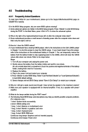
...or graphics card error 1 long, 3 short: Keyboard error 1 long, 9 short: BIOS ROM error Continuous long beeps: Graphics card not inserted properly Continuous short beeps: Power error GA-M61SME-S2 Motherboard - 74 - 4-2 Troubleshooting 4-2-1 Frequently Asked Questions To read more FAQs for 5 seconds.) 3. Press to restart your motherboard has a clearing CMOS jumper, refer to the Support\Motherboard\FAQ page on . Saves changes and exit BIOS Setup (select "Save & Exit Setup") to enter BIOS Setup during the POST mean? In the Main Menu, press + to load BIOS default settings. 6. If...
...or graphics card error 1 long, 3 short: Keyboard error 1 long, 9 short: BIOS ROM error Continuous long beeps: Graphics card not inserted properly Continuous short beeps: Power error GA-M61SME-S2 Motherboard - 74 - 4-2 Troubleshooting 4-2-1 Frequently Asked Questions To read more FAQs for 5 seconds.) 3. Press to restart your motherboard has a clearing CMOS jumper, refer to the Support\Motherboard\FAQ page on . Saves changes and exit BIOS Setup (select "Save & Exit Setup") to enter BIOS Setup during the POST mean? In the Main Menu, press + to load BIOS default settings. 6. If...


