Manual
Page 4
... ...6 GA-M61PME-S2P Motherboard Layout 7 Block Diagram ...8 Chapter 1 Hardware Installation 9 1-1 Installation Precautions 9 1-2 Product Specifications 10 1-3 Installing the CPU and CPU Cooler 12 1-3-1 Installing the CPU 12 1-3-2 Installing the CPU Cooler 14 1-4 Installing the Memory 15 1-4-1 Dual Channel Memory Configuration 15 1-4-2 Installing a Memory 16 1-5 Installing an Expansion Card 17 1-6 Back Panel Connectors 18 1-7 Internal Connectors 20 Chapter 2 BIOS Setup 31 2-1 Startup Screen 32 2-2 The Main Menu 33 2-3 Standard CMOS Features 35 2-4 Advanced BIOS Features...
... ...6 GA-M61PME-S2P Motherboard Layout 7 Block Diagram ...8 Chapter 1 Hardware Installation 9 1-1 Installation Precautions 9 1-2 Product Specifications 10 1-3 Installing the CPU and CPU Cooler 12 1-3-1 Installing the CPU 12 1-3-2 Installing the CPU Cooler 14 1-4 Installing the Memory 15 1-4-1 Dual Channel Memory Configuration 15 1-4-2 Installing a Memory 16 1-5 Installing an Expansion Card 17 1-6 Back Panel Connectors 18 1-7 Internal Connectors 20 Chapter 2 BIOS Setup 31 2-1 Startup Screen 32 2-2 The Main Menu 33 2-3 Standard CMOS Features 35 2-4 Advanced BIOS Features...
Manual
Page 5
... 55 4-2 BIOS Update Utilities 58 4-2-1 Updating the BIOS with the Q-Flash Utility 58 4-2-2 Updating the BIOS with the @BIOS Utility 61 4-3 EasyTune 5 ...63 Chapter 5 Appendix ...65 5-1 Configuring SATA Hard Drive(s 65 5-1-1 Configuring the Onboard SATA Controller 65 5-1-2 Making a SATA RAID Driver Diskette for Windows XP 70 5-1-3 Installing the SATA RAID Driver and Operating System 71 5-2 ConfiguringAudio Input and Output 73 5-2-1 Configuring 2/4/5.1/7.1-Channel Audio 73 5-2-2 Configuring S/PDIF In/Out 76 5-2-3 Configuring Microphone Recording 78 5-2-4 Using the Sound Recorder 80...
... 55 4-2 BIOS Update Utilities 58 4-2-1 Updating the BIOS with the Q-Flash Utility 58 4-2-2 Updating the BIOS with the @BIOS Utility 61 4-3 EasyTune 5 ...63 Chapter 5 Appendix ...65 5-1 Configuring SATA Hard Drive(s 65 5-1-1 Configuring the Onboard SATA Controller 65 5-1-2 Making a SATA RAID Driver Diskette for Windows XP 70 5-1-3 Installing the SATA RAID Driver and Operating System 71 5-2 ConfiguringAudio Input and Output 73 5-2-1 Configuring 2/4/5.1/7.1-Channel Audio 73 5-2-2 Configuring S/PDIF In/Out 76 5-2-3 Configuring Microphone Recording 78 5-2-4 Using the Sound Recorder 80...
Manual
Page 10
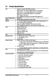
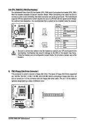
... SATA RAID 0 and RAID 1 iTE IT8718 chip: - 1 x floppy disk drive connector supporting up to the internal USB headers) 1 x 24-pin ATX main power connector 1 x 4-pin ATX 12V power connector 1 x floppy disk drive connector 1 x IDE connector 2 x SATA 3Gb/s connectors 1 x CPU fan header 1 x system fan header 1 x front panel header 1 x front panel audio header 1 x surround/center audio header GA-M61PME-S2P Motherboard - 10 - Support for CD In RTL 8201CL chip (10/100 Mbit) 1 x PCI Express x16 slot, running at x16 1 x PCI Express x1 slot 2 x PCI slots NVIDIA® GeForce 6100/nForce 430 chipset...
... SATA RAID 0 and RAID 1 iTE IT8718 chip: - 1 x floppy disk drive connector supporting up to the internal USB headers) 1 x 24-pin ATX main power connector 1 x 4-pin ATX 12V power connector 1 x floppy disk drive connector 1 x IDE connector 2 x SATA 3Gb/s connectors 1 x CPU fan header 1 x system fan header 1 x front panel header 1 x front panel audio header 1 x surround/center audio header GA-M61PME-S2P Motherboard - 10 - Support for CD In RTL 8201CL chip (10/100 Mbit) 1 x PCI Express x16 slot, running at x16 1 x PCI Express x1 slot 2 x PCI slots NVIDIA® GeForce 6100/nForce 430 chipset...
Manual
Page 17
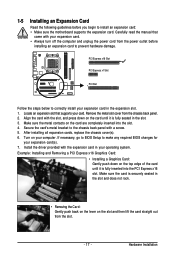
... to install an expansion card: • Make sure the motherboard supports the expansion card. After installing all expansion cards, replace the chassis cover(s). 6. Install the driver provided with a screw. 5. Example: Installing and Removing a PCI Express x16 Graphics Card: • Installing a Graphics Card: Gently push down on the slot and then lift the card straight out from the chassis back panel. 2. If necessary, go to BIOS Setup to make any required BIOS changes for your computer. Locate an expansion slot that...
... to install an expansion card: • Make sure the motherboard supports the expansion card. After installing all expansion cards, replace the chassis cover(s). 6. Install the driver provided with a screw. 5. Example: Installing and Removing a PCI Express x16 Graphics Card: • Installing a Graphics Card: Gently push down on the slot and then lift the card straight out from the chassis back panel. 2. If necessary, go to BIOS Setup to make any required BIOS changes for your computer. Locate an expansion slot that...
Manual
Page 22
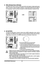
... installed inside the chassis. 1 CPU_FAN 1 SYS_FAN CPU_FAN: Pin No. 1 2 3 4 SYS_FAN: Pin No. 1 2 3 Definition GND +12V / Speed Control Sense Speed Control Definition GND +12V Sense • Be sure to connect fan cables to the fan headers to locate pin 1 of different color. 33 1 34 2 GA-M61PME-S2P Motherboard - 22 - Before connecting a floppy disk drive, be sure to prevent your CPU and system from overheating. Do not place a jumper cap on the headers. 5) FDD (Floppy Disk Drive Connector) This connector is the ground wire...
... installed inside the chassis. 1 CPU_FAN 1 SYS_FAN CPU_FAN: Pin No. 1 2 3 4 SYS_FAN: Pin No. 1 2 3 Definition GND +12V / Speed Control Sense Speed Control Definition GND +12V Sense • Be sure to connect fan cables to the fan headers to locate pin 1 of different color. 33 1 34 2 GA-M61PME-S2P Motherboard - 22 - Before connecting a floppy disk drive, be sure to prevent your CPU and system from overheating. Do not place a jumper cap on the headers. 5) FDD (Floppy Disk Drive Connector) This connector is the ground wire...
Manual
Page 24
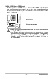
... use a metal object like a screwdriver to replace the battery by removing the battery: 1. GA-M61PME-S2P Motherboard - 24 - Replace the battery. 4. Plug in the CMOS when the computer is turned off your computer and unplug the power cord. 2. Replace the battery when the battery voltage drops to keep the values (such as BIOS configurations, date, and time information) in the power cord and restart your computer. • Always turn off . System Status LED S0...
... use a metal object like a screwdriver to replace the battery by removing the battery: 1. GA-M61PME-S2P Motherboard - 24 - Replace the battery. 4. Plug in the CMOS when the computer is turned off your computer and unplug the power cord. 2. Replace the battery when the battery voltage drops to keep the values (such as BIOS configurations, date, and time information) in the power cord and restart your computer. • Always turn off . System Status LED S0...
Manual
Page 26
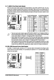
... this header and configure audio output mode via the audio software in Chapter 5, "Configuring 2/4/5.1-Channel Audio." • Audio signals will make the device unable to work or even damage it. For purchasing the optional 5.1/7.1 surround cable, please contact the local dealer. 2 14 1 13 Pin No. 1 2 3 4 5 6 7 8 9 10 11 12 13 14 Definition LEF_P SURR_RR CEN_P SURR_LL CEN_JD SURR_JD GND -SUR_DET GND No Pin GND S_SURR_JD S_SURR_LL S_SURR_RR GA-M61PME-S2P Motherboard...
... this header and configure audio output mode via the audio software in Chapter 5, "Configuring 2/4/5.1-Channel Audio." • Audio signals will make the device unable to work or even damage it. For purchasing the optional 5.1/7.1 surround cable, please contact the local dealer. 2 14 1 13 Pin No. 1 2 3 4 5 6 7 8 9 10 11 12 13 14 Definition LEF_P SURR_RR CEN_P SURR_LL CEN_JD SURR_JD GND -SUR_DET GND No Pin GND S_SURR_JD S_SURR_LL S_SURR_RR GA-M61PME-S2P Motherboard...
Manual
Page 29
Failure to do so may cause damage to the motherboard. • After system restart, go to BIOS Setup to load factory defaults (select Load Optimized Defaults) or manually configure the BIOS settings (refer to remove the jumper cap from the power outlet before clearing the CMOS values. • After clearing the CMOS values and before turning on the two pins to temporarily short the two pins or use a metal object like a screwdriver to touch the...
Failure to do so may cause damage to the motherboard. • After system restart, go to BIOS Setup to load factory defaults (select Load Optimized Defaults) or manually configure the BIOS settings (refer to remove the jumper cap from the power outlet before clearing the CMOS values. • After clearing the CMOS values and before turning on the two pins to temporarily short the two pins or use a metal object like a screwdriver to touch the...
Manual
Page 31
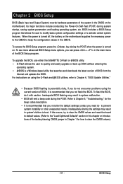
... user to modify basic system configuration settings or to Chapter 5, "Troubleshooting," for how to boot. If this occurs, try to clear the CMOS values and reset the board to default values. (Refer to the "Load Optimized Defaults" section in this chapter or introductions of the battery/clearing CMOS jumper in system's failure to clear the CMOS values.) - 31 - Inadequate BIOS flashing may result in Chapter 1 for the beep codes description. • It is turned...
... user to modify basic system configuration settings or to Chapter 5, "Troubleshooting," for how to boot. If this occurs, try to clear the CMOS values and reset the board to default values. (Refer to the "Load Optimized Defaults" section in this chapter or introductions of the battery/clearing CMOS jumper in system's failure to clear the CMOS values.) - 31 - Inadequate BIOS flashing may result in Chapter 1 for the beep codes description. • It is turned...
Manual
Page 37
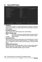
... arrow key to select a hard drive, then press the plus key (or ) or the minus key (or ) to move it up or down on the list. BIOS Setup 2-4 Advanced BIOS Features CMOS Setup Utility-Copyright (C) 1984-2008 Award Software Advanced BIOS Features Virtualization Patch AMD TLB Erratum (Note) AMD K8 Cool&Quiet control Hard Disk Boot Priority First Boot Device Second Boot Device Third Boot Device Password Check HDD S.M.A.R.T. Capability Away Mode Init Display First Frame Buffer Size Onboard GPU [Disabled] [Enabled] [Auto] [Press Enter] [Floppy] [Hard Disk] [CDROM] [Setup] [Disabled...
... arrow key to select a hard drive, then press the plus key (or ) or the minus key (or ) to move it up or down on the list. BIOS Setup 2-4 Advanced BIOS Features CMOS Setup Utility-Copyright (C) 1984-2008 Award Software Advanced BIOS Features Virtualization Patch AMD TLB Erratum (Note) AMD K8 Cool&Quiet control Hard Disk Boot Priority First Boot Device Second Boot Device Third Boot Device Password Check HDD S.M.A.R.T. Capability Away Mode Init Display First Frame Buffer Size Onboard GPU [Disabled] [Enabled] [Auto] [Press Enter] [Floppy] [Hard Disk] [CDROM] [Setup] [Disabled...
Manual
Page 38
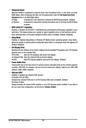
...set up a dual view configuration, set the password(s) under the Set Supervisor/User Password item in Windows XP Media Center operating system. If you enter BIOS Setup. MS-DOS, for example, will use only this item to report read/write errors of the monitor display from the installed PCI graphics card, PCI Express graphics card, or the onboard VGA. Password Check Specifies whether a password is installed. Capability Enables or disables the S.M.A.R.T. (Self Monitoring and Reporting Technology) capability of your system to Always Enable. GA-M61PME-S2P Motherboard...
...set up a dual view configuration, set the password(s) under the Set Supervisor/User Password item in Windows XP Media Center operating system. If you enter BIOS Setup. MS-DOS, for example, will use only this item to report read/write errors of the monitor display from the installed PCI graphics card, PCI Express graphics card, or the onboard VGA. Password Check Specifies whether a password is installed. Capability Enables or disables the S.M.A.R.T. (Self Monitoring and Reporting Technology) capability of your system to Always Enable. GA-M61PME-S2P Motherboard...
Manual
Page 39
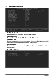
... hard drive performance. (Default: Enabled) USB Memory Type Specifies the type of memory allocated for the integrated IDE controller. 2-5 Integrated Peripherals CMOS Setup Utility-Copyright (C) 1984-2008 Award Software Integrated Peripherals On-Chip IDE Channel NV SATA Controller IDE Prefetch Mode USB Memory Type Serial-ATA RAID Config Onboard Audio Function On-Chip MAC Lan Onboard LAN Boot ROM Onboard Serial Port 1 Onboard Parallel Port Parallel Port Mode x ECP Mode Use DMA On-Chip USB USB Keyboard Support USB Mouse Support Legacy USB storage detect [Enabled] [Enabled] [Enabled...
... hard drive performance. (Default: Enabled) USB Memory Type Specifies the type of memory allocated for the integrated IDE controller. 2-5 Integrated Peripherals CMOS Setup Utility-Copyright (C) 1984-2008 Award Software Integrated Peripherals On-Chip IDE Channel NV SATA Controller IDE Prefetch Mode USB Memory Type Serial-ATA RAID Config Onboard Audio Function On-Chip MAC Lan Onboard LAN Boot ROM Onboard Serial Port 1 Onboard Parallel Port Parallel Port Mode x ECP Mode Use DMA On-Chip USB USB Keyboard Support USB Mouse Support Legacy USB storage detect [Enabled] [Enabled] [Enabled...
Manual
Page 40
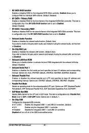
... to Enabled. (Default: Enabled) NV SATA 1 Secondary RAID Enables or disables RAID for the LPT port in audio card instead of the integrated SATA 3Gb/s controller. Onboard LAN Boot ROM Allows you wish to install a 3rd party add-in network card instead of the USB functionalities below. Parallel Port Mode Selects an operating mode for the integrated SATA 3Gb/s controller. Options are : Auto, 3F8/IRQ4 (default), 2F8/IRQ3, 3E8/IRQ4, 2E8/IRQ3, Disabled. Disables the integrated USB 1.1 and USB 2.0 controllers. GA-M61PME-S2P Motherboard - 40 - This item is configurable...
... to Enabled. (Default: Enabled) NV SATA 1 Secondary RAID Enables or disables RAID for the LPT port in audio card instead of the integrated SATA 3Gb/s controller. Onboard LAN Boot ROM Allows you wish to install a 3rd party add-in network card instead of the USB functionalities below. Parallel Port Mode Selects an operating mode for the integrated SATA 3Gb/s controller. Options are : Auto, 3F8/IRQ4 (default), 2F8/IRQ3, 3E8/IRQ4, 2E8/IRQ3, Disabled. Disables the integrated USB 1.1 and USB 2.0 controllers. GA-M61PME-S2P Motherboard - 40 - This item is configurable...
Manual
Page 58
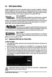
4-2 BIOS Update Utilities GIGABYTE motherboards provide two unique BIOS update tools, Q-FlashTM and @BIOSTM. For the sake of your computer by either pressing the key during the POST to an independent IDE/SATA controller, use FAT32/16/12 file system. 3. From GIGABYTE's website, download the latest compressed BIOS update file that support DualBIOS have two BIOS onboard, a main BIOS and a backup BIOS. However, if the BIOS update file is potentially risky, please do it with the Q-Flash Utility A. GA-M61PME-S2P Motherboard - 58 - Additionally, this...
4-2 BIOS Update Utilities GIGABYTE motherboards provide two unique BIOS update tools, Q-FlashTM and @BIOSTM. For the sake of your computer by either pressing the key during the POST to an independent IDE/SATA controller, use FAT32/16/12 file system. 3. From GIGABYTE's website, download the latest compressed BIOS update file that support DualBIOS have two BIOS onboard, a main BIOS and a backup BIOS. However, if the BIOS update file is potentially risky, please do it with the Q-Flash Utility A. GA-M61PME-S2P Motherboard - 58 - Additionally, this...
Manual
Page 59
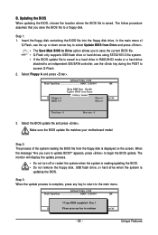
... BIOS file. • Q-Flash only supports USB flash drive or hard drives using FAT32/16/12 file system. • If the BIOS update file is saved to a hard drive in RAID/AHCI mode or a hard drive attached to an independent IDE/SATA controller, use the key during the POST to the main menu. CoUpypdBaItOe SBIcOomS pfrloetmedD-rPivaess !! Select Floppy A and press . Step 3: When the update process is displayed on the screen. The follow procedure assumes that you to save the BIOS file to a floppy disk. Q-Flash Utility v2.08 Flash Type/Size...
... BIOS file. • Q-Flash only supports USB flash drive or hard drives using FAT32/16/12 file system. • If the BIOS update file is saved to a hard drive in RAID/AHCI mode or a hard drive attached to an independent IDE/SATA controller, use the key during the POST to the main menu. CoUpypdBaItOe SBIcOomS pfrloetmedD-rPivaess !! Select Floppy A and press . Step 3: When the update process is displayed on the screen. The follow procedure assumes that you to save the BIOS file to a floppy disk. Q-Flash Utility v2.08 Flash Type/Size...
Manual
Page 65
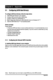
...Install the SATA RAID driver (Note) and operating system. Then connect the power connector from your power supply to the hard drive. (Note ) Skip this step if you do not want to available SATA port on the SATA controller. - 65 - Configure SATA controller mode in your computer Attach one hard drive. • An empty formatted floppy disk. • Windows Vista/XP setup disk. • Motherboard driver disk. 5-1-1 Configuring the Onboard SATA Controller A. Installing SATA hard drive(s) in RAID BIOS. (Note) D. Install SATA hard drive(s) in BIOS Setup. Appendix Configure a RAID...
...Install the SATA RAID driver (Note) and operating system. Then connect the power connector from your power supply to the hard drive. (Note ) Skip this step if you do not want to available SATA port on the SATA controller. - 65 - Configure SATA controller mode in your computer Attach one hard drive. • An empty formatted floppy disk. • Windows Vista/XP setup disk. • Motherboard driver disk. 5-1-1 Configuring the Onboard SATA Controller A. Installing SATA hard drive(s) in RAID BIOS. (Note) D. Install SATA hard drive(s) in BIOS Setup. Appendix Configure a RAID...
Manual
Page 70
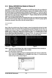
...-DOS mode (Note 2). Boot from the menu. Figure 1 Figure 2 (Note 1) If you need to install the SATA controller driver during the Windows XP setup process (Note 1). Once at the A:\> prompt, change to your RAID hard drives, select 2) NVIDIA GeForce 6100/nForce 520LE Series RAID Driver(XP). The 3) NVIDIA GeForce 6100/ nForce 520LE Series RAID Driver(64-Bit) is installed. (Note 2) For users without a startup disk: Use an alternative system and insert the motherboard driver disk. See the instructions...
...-DOS mode (Note 2). Boot from the menu. Figure 1 Figure 2 (Note 1) If you need to install the SATA controller driver during the Windows XP setup process (Note 1). Once at the A:\> prompt, change to your RAID hard drives, select 2) NVIDIA GeForce 6100/nForce 520LE Series RAID Driver(XP). The 3) NVIDIA GeForce 6100/ nForce 520LE Series RAID Driver(64-Bit) is installed. (Note 2) For users without a startup disk: Use an alternative system and insert the motherboard driver disk. See the instructions...
Manual
Page 71
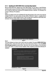
... the floppy disk containing the SATA RAID driver and press and a screen similar to that installation of Windows XP installation. When completed, proceed with Windows, using a device support disk provided by an adapter manufacturer. NVIDIA RAID Driver (required) NVIDIA nForce Storage Controller (required) ENTER=Select F3=Exit Figure 2 - 71 - 5-1-3 Installing the SATA RAID Driver and Operating System With the SATA RAID driver diskette and correct BIOS settings, you are ready to install Windows operating system onto your system to boot from...
... the floppy disk containing the SATA RAID driver and press and a screen similar to that installation of Windows XP installation. When completed, proceed with Windows, using a device support disk provided by an adapter manufacturer. NVIDIA RAID Driver (required) NVIDIA nForce Storage Controller (required) ENTER=Select F3=Exit Figure 2 - 71 - 5-1-3 Installing the SATA RAID Driver and Operating System With the SATA RAID driver diskette and correct BIOS settings, you are ready to install Windows operating system onto your system to boot from...
Manual
Page 74
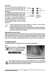
... updated with the latest Service Pack for each jack through the audio driver. Line In Line Out (Front Speaker Out) Mic In Audio Jacks on the next page. GA-M61PME-S2P Motherboard - 74 - For example, users can retask the Center/Subwoofer speaker out jack to the three onboard audio jacks. The Center/Subwoofer Speaker Out picture to change the function for Windows. B. Rear Speaker Out The integrated HD (High...
... updated with the latest Service Pack for each jack through the audio driver. Line In Line Out (Front Speaker Out) Mic In Audio Jacks on the next page. GA-M61PME-S2P Motherboard - 74 - For example, users can retask the Center/Subwoofer speaker out jack to the three onboard audio jacks. The Center/Subwoofer Speaker Out picture to change the function for Windows. B. Rear Speaker Out The integrated HD (High...
Manual
Page 81
... battery from the battery holder to stop supplying power to the Support\Motherboard\FAQ page on the CLR_CMOS jumper in Chapter 1. A: The following Award BIOS beep code descriptions may help you identify possible computer problems. (For reference only.) 1 short: System boots successfully 2 short: CMOS setting error 1 long, 1 short: Memory or motherboard error 1 long, 2 short: Monitor or graphics card error 1 long, 3 short: Keyboard error 1 long, 9 short: BIOS ROM error Continuous long beeps: Graphics card not inserted properly Continuous short beeps: Power error - 81 - In the Main Menu...
... battery from the battery holder to stop supplying power to the Support\Motherboard\FAQ page on the CLR_CMOS jumper in Chapter 1. A: The following Award BIOS beep code descriptions may help you identify possible computer problems. (For reference only.) 1 short: System boots successfully 2 short: CMOS setting error 1 long, 1 short: Memory or motherboard error 1 long, 2 short: Monitor or graphics card error 1 long, 3 short: Keyboard error 1 long, 9 short: BIOS ROM error Continuous long beeps: Graphics card not inserted properly Continuous short beeps: Power error - 81 - In the Main Menu...


