Manual
Page 10
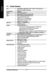
...Dual-Core / AthlonTM 64 / SempronTM processor Front Side Bus Š 2000 MHz Chipset Š nVIDIA® nForce 570-SLI LAN Š Marvell 88E1116 phy (10/100/1000 Mbit) Audio Š Onboard Realtek ALC888 CODEC chip Š Supports High Definition Audio Š Supports 2 / 4 / 6 / 8 channel audio Š Supports S/PDIF In/Out connection Š Supports CD In connection IEEE 1394 Š Onboard T.I. English 1-2 Feature Summary CPU Š Socket AM2 for additional 2 ports by cables Š 1 chassis intrusion connector Š 1 power LED connector GA-M57SLI-S4 Motherboard...
...Dual-Core / AthlonTM 64 / SempronTM processor Front Side Bus Š 2000 MHz Chipset Š nVIDIA® nForce 570-SLI LAN Š Marvell 88E1116 phy (10/100/1000 Mbit) Audio Š Onboard Realtek ALC888 CODEC chip Š Supports High Definition Audio Š Supports 2 / 4 / 6 / 8 channel audio Š Supports S/PDIF In/Out connection Š Supports CD In connection IEEE 1394 Š Onboard T.I. English 1-2 Feature Summary CPU Š Socket AM2 for additional 2 ports by cables Š 1 chassis intrusion connector Š 1 power LED connector GA-M57SLI-S4 Motherboard...
Manual
Page 11
...; 1 serial port Š 4 USB 2.0/1.1 ports Š 1 IEEE 1394a port Š 1 RJ-45 port Š 6 audio jacks (Line In / Line Out / MIC In / Surround Speaker Out (Rear Speaker Out) / Center/Subwoofer Speaker Out / Side Speaker Out) I/O Control Š IT8716 chip Hardware Monitor Š System voltage detection Š CPU temperature detection Š CPU / Power / System fan speed detection Š CPU warning temperature Š CPU / Power / System fan failure warning Š Supports CPU Smart Fan function (Note 2) BIOS Š 1 4 Mbit flash ROM Š Use of licensed AWARD BIOS...
...; 1 serial port Š 4 USB 2.0/1.1 ports Š 1 IEEE 1394a port Š 1 RJ-45 port Š 6 audio jacks (Line In / Line Out / MIC In / Surround Speaker Out (Rear Speaker Out) / Center/Subwoofer Speaker Out / Side Speaker Out) I/O Control Š IT8716 chip Hardware Monitor Š System voltage detection Š CPU temperature detection Š CPU / Power / System fan speed detection Š CPU warning temperature Š CPU / Power / System fan failure warning Š Supports CPU Smart Fan function (Note 2) BIOS Š 1 4 Mbit flash ROM Š Use of licensed AWARD BIOS...

Manual
Page 19
... in the side menu and then select the Enable SLI multi-GPU checkbox in your graphics card for more information about enabing SLI mode. - 19 - Then the SLI configuration is completed. Refer to the user's manual that came with your system tray and then select NVIDIA Display. The NVIDIA control panel will restart after you click Apply. English Configuring the Graphics Card Driver: Step 1: After installing graphics card driver in operating system...
... in the side menu and then select the Enable SLI multi-GPU checkbox in your graphics card for more information about enabing SLI mode. - 19 - Then the SLI configuration is completed. Refer to the user's manual that came with your system tray and then select NVIDIA Display. The NVIDIA control panel will restart after you click Apply. English Configuring the Graphics Card Driver: Step 1: After installing graphics card driver in operating system...
Manual
Page 20
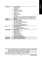
... IEEE 1394 port supports the IEEE 1394a specification, featuring high speed, high bandwidth and hotplug capabilities. Use this feature, ensure that your audio system provides an optical digital audio in connector. RJ-45 LAN Port The Gigabit Ethernet LAN port provides Internet connection at up to connect a PS/2 keyboard. The parallel port is not established GA-M57SLI-S4 Motherboard - 20 - Before using this port for USB devices such as an USB keyboard/mouse, USB printer, USB flash drive and etc. Use this feature...
... IEEE 1394 port supports the IEEE 1394a specification, featuring high speed, high bandwidth and hotplug capabilities. Use this feature, ensure that your audio system provides an optical digital audio in connector. RJ-45 LAN Port The Gigabit Ethernet LAN port provides Internet connection at up to connect a PS/2 keyboard. The parallel port is not established GA-M57SLI-S4 Motherboard - 20 - Before using this port for USB devices such as an USB keyboard/mouse, USB printer, USB flash drive and etc. Use this feature...
Manual
Page 24
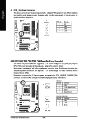
... GND 2 +12V 3 Sense GA-M57SLI-S4 Motherboard - 24 - A red power connector wire indicates a positive connection and requires a +12V power voltage. Definition 1 NC 2 GND 3 GND 4 +12V 4/5/6) CPU_FAN / SYS_FAN / PWR_FAN (Cooler Fan Power Connector) The cooler fan power connector supplies a +12V power voltage via a 3-pin/4-pin (only for CPU_FAN) power connector and possesses a foolproof connection design. The black connector wire is the ground wire (GND). When installing two graphics cards, please connect the power cable from the power supply to prevent CPU damage or system...
... GND 2 +12V 3 Sense GA-M57SLI-S4 Motherboard - 24 - A red power connector wire indicates a positive connection and requires a +12V power voltage. Definition 1 NC 2 GND 3 GND 4 +12V 4/5/6) CPU_FAN / SYS_FAN / PWR_FAN (Cooler Fan Power Connector) The cooler fan power connector supplies a +12V power voltage via a 3-pin/4-pin (only for CPU_FAN) power connector and possesses a foolproof connection design. The black connector wire is the ground wire (GND). When installing two graphics cards, please connect the power cable from the power supply to prevent CPU damage or system...
Manual
Page 26
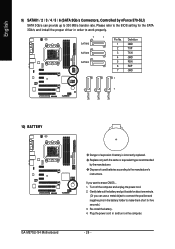
... GND 1 7 10) BATTERY GA-M57SLI-S4 Motherboard Danger of used batteries according to the BIOS setting for five seconds.) 3. Please refer to the manufacturer's instructions. Replace only with the same or equivalent type recommended by nForce 570-SLI) SATA 3Gb/s can use a metal object to connect the positive and negative pins in the battery holder to make them short for the SATA 3Gb/s and install the proper driver in and turn on the...
... GND 1 7 10) BATTERY GA-M57SLI-S4 Motherboard Danger of used batteries according to the BIOS setting for five seconds.) 3. Please refer to the manufacturer's instructions. Replace only with the same or equivalent type recommended by nForce 570-SLI) SATA 3Gb/s can use a metal object to connect the positive and negative pins in the battery holder to make them short for the SATA 3Gb/s and install the proper driver in and turn on the...
Manual
Page 28
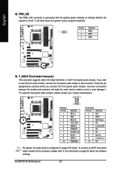
... AC'97 Audio: Pin No. Definition 1 MIC 2 GND 3 MIC Power 4 NC 5 Line Out (R) 6 NC 7 NC 8 No Pin 9 Line Out (L) 10 NC By default, the audio driver is on page 80 about the software settings. If you connect the front panel audio module. GA-M57SLI-S4 Motherboard - 28 - Pin No. English 12) PWR_LED The PWR_LED connector is connected with the system power indicator to indicate whether the system is configured to support HD Audio.
... AC'97 Audio: Pin No. Definition 1 MIC 2 GND 3 MIC Power 4 NC 5 Line Out (R) 6 NC 7 NC 8 No Pin 9 Line Out (L) 10 NC By default, the audio driver is on page 80 about the software settings. If you connect the front panel audio module. GA-M57SLI-S4 Motherboard - 28 - Pin No. English 12) PWR_LED The PWR_LED connector is connected with the system power indicator to indicate whether the system is configured to support HD Audio.
Manual
Page 34
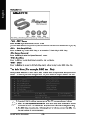
... BIOS Features Integrated Peripherals Power Management Setup PnP/PCI Configurations PC Health Status MB Intelligent Tweaker(M.I.T.) Load Fail-Safe Defaults Load Optimized Defaults Set Supervisor Password Set User Password Save & Exit Setup Exit Without Saving Esc: Quit F8: Q-Flash : Select Item F10: Save & Exit Setup F11: Save CMOS to BIOS F12: Load CMOS from the exact settings for your motherboard. GA-M57SLI-S4 Motherboard - 34 - The BIOS Setup menus described in BIOS Setup. : Xpress Recovery2 Press the F9 key to enter the Xpress Recovery2 screen. : Boot Menu...
... BIOS Features Integrated Peripherals Power Management Setup PnP/PCI Configurations PC Health Status MB Intelligent Tweaker(M.I.T.) Load Fail-Safe Defaults Load Optimized Defaults Set Supervisor Password Set User Password Save & Exit Setup Exit Without Saving Esc: Quit F8: Q-Flash : Select Item F10: Save & Exit Setup F11: Save CMOS to BIOS F12: Load CMOS from the exact settings for your motherboard. GA-M57SLI-S4 Motherboard - 34 - The BIOS Setup menus described in BIOS Setup. : Xpress Recovery2 Press the F9 key to enter the Xpress Recovery2 screen. : Boot Menu...
Manual
Page 36
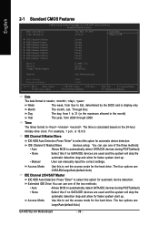
...:0:0. IDE Channel 0 Master/Slave IDE HDD Auto-Detection Press "Enter" to automatically detect SATA/IDE devices during POST(default) • None Select this option for faster system start up . You can use one of the three methods: • Auto Allows BIOS to select this if no SATA/IDE devices are used and the system will skip the automatic detection step and allow for automatic device detection. The four options are : Large/Auto(default:Auto) GA-M57SLI-S4 Motherboard - 36 - IDE Channel...
...:0:0. IDE Channel 0 Master/Slave IDE HDD Auto-Detection Press "Enter" to automatically detect SATA/IDE devices during POST(default) • None Select this option for faster system start up . You can use one of the three methods: • Auto Allows BIOS to select this if no SATA/IDE devices are used and the system will skip the automatic detection step and allow for automatic device detection. The four options are : Large/Auto(default:Auto) GA-M57SLI-S4 Motherboard - 36 - IDE Channel...

Manual
Page 39
... prompt. (Default value) HDD S.M.A.R.T. Set Init Display First to PCI Express VGA card (the PCIE_16_1 slot). (Default value) PEG (Slot2) Set Init Display First to Setup page will be denied if the correct password is not entered at the prompt. Enabled Enable HDD S.M.A.R.T. Disabled BIOS will not search for floppy disk drive to PCI VGA card. capability. (Default value) Away Mode Disabled Enabled Disable this function. BIOS Setup English Boot Up Floppy Seek During POST, BIOS will determine the floppy disk drive installed is 40 or 80 tracks. 360 KB type is...
... prompt. (Default value) HDD S.M.A.R.T. Set Init Display First to PCI Express VGA card (the PCIE_16_1 slot). (Default value) PEG (Slot2) Set Init Display First to Setup page will be denied if the correct password is not entered at the prompt. Enabled Enable HDD S.M.A.R.T. Disabled BIOS will not search for floppy disk drive to PCI VGA card. capability. (Default value) Away Mode Disabled Enabled Disable this function. BIOS Setup English Boot Up Floppy Seek During POST, BIOS will determine the floppy disk drive installed is 40 or 80 tracks. 360 KB type is...

Manual
Page 47
... show "Yes." BIOS Setup English 2-6 PC Health Status CMOS Setup Utility-Copyright (C) 1984-2007 Award Software PC Health Status Reset Case Open Status Case Opened Vcore DDR2 1.8V +3.3V +12V Current CPU Temperature Current CPU FAN Speed Current POWER FAN Speed Current SYSTEM FAN Speed CPU Warning Temperature CPU FAN Fail Warning POWER FAN Fail Warning SYSTEM FAN Fail Warning CPU Smart FAN Control (Note) CPU Smart FAN Mode [Disabled] Yes OK OK OK OK 45oC 3245 RPM 0 RPM 0 RPM [Disabled] [Disabled] [Disabled] [Disabled] [Enabled] [Auto] Item Help Menu Level : Move Enter: Select F5...
... show "Yes." BIOS Setup English 2-6 PC Health Status CMOS Setup Utility-Copyright (C) 1984-2007 Award Software PC Health Status Reset Case Open Status Case Opened Vcore DDR2 1.8V +3.3V +12V Current CPU Temperature Current CPU FAN Speed Current POWER FAN Speed Current SYSTEM FAN Speed CPU Warning Temperature CPU FAN Fail Warning POWER FAN Fail Warning SYSTEM FAN Fail Warning CPU Smart FAN Control (Note) CPU Smart FAN Mode [Disabled] Yes OK OK OK OK 45oC 3245 RPM 0 RPM 0 RPM [Disabled] [Disabled] [Disabled] [Disabled] [Enabled] [Auto] Item Help Menu Level : Move Enter: Select F5...
Manual
Page 52
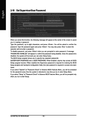
... Setup F11: Save CMOS to BIOS F12: Load CMOS from BIOS Change/Set/Disable Password When you select this function, the following message will appear at the center of the screen to assist you to specify two separate passwords: SUPERVISOR PASSWORD and a USER PASSWORD. To disable password, just press when you can enter Setup freely. GA-M57SLI-S4 Motherboard - 52 - Type the password, up to confirm the password being disabled. Type the password again and press . When enabled, the Supervisor password...
... Setup F11: Save CMOS to BIOS F12: Load CMOS from BIOS Change/Set/Disable Password When you select this function, the following message will appear at the center of the screen to assist you to specify two separate passwords: SUPERVISOR PASSWORD and a USER PASSWORD. To disable password, just press when you can enter Setup freely. GA-M57SLI-S4 Motherboard - 52 - Type the password, up to confirm the password being disabled. Type the password again and press . When enabled, the Supervisor password...

Manual
Page 55
... the Install button following instructions use Windows XP as the example operating system.) • After installing the operating system, insert the driver disk into your system. Or you wish to restart your optional drive. After installing the SP1 (or later), if a question mark still exists in Universal Serial Bus Controller in the CD-ROM. • For USB 2.0 driver support under the Windows XP operating system, please install the Windows XP Service Pack...
... the Install button following instructions use Windows XP as the example operating system.) • After installing the operating system, insert the driver disk into your system. Or you wish to restart your optional drive. After installing the SP1 (or later), if a question mark still exists in Universal Serial Bus Controller in the CD-ROM. • For USB 2.0 driver support under the Windows XP operating system, please install the Windows XP Service Pack...
Manual
Page 60
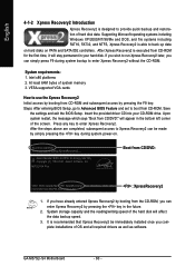
... installations of the screen. M57SLI-S4 FAa . . . . : BIOS Setup/Q-Flash : XpressRecovery2 : Boot Menu : Qflash 03/22/2007-NV-MCP55-6A61JG0AC-00 : XpressRecovery2 1. If you wish to run Xpress Recovery2 later, you can simply press F9 during system power-on PATA and SATA IDE controllers. Intel x86 platforms 2. Insert the provided driver CD into your hard disk. Upon system restart, the message which says "Boot from CD-ROM. System storage...
... installations of the screen. M57SLI-S4 FAa . . . . : BIOS Setup/Q-Flash : XpressRecovery2 : Boot Menu : Qflash 03/22/2007-NV-MCP55-6A61JG0AC-00 : XpressRecovery2 1. If you wish to run Xpress Recovery2 later, you can simply press F9 during system power-on PATA and SATA IDE controllers. Intel x86 platforms 2. Insert the provided driver CD into your hard disk. Upon system restart, the message which says "Boot from CD-ROM. System storage...
Manual
Page 62
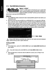
... ESC:Reset :Power Off HDD 0-0 Total size : 0 GA-M57SLI-S4 Motherboard Free size : 0 - 62 - Restart the system. Award Modular BIOS v6.00PG, An Energy Star Ally Copyright (C) 1984-2006, Award Software, Inc. Note: You can access Q-Flash by either pressing the key during the POST to access Q-Flash. Updating the BIOS Step 1: a. Q-Flash Utility v2.02 Flash Type/Size PMC 25LV040 512K Keep DMI Data Enable Update BIOS from Drive and press ENTER. Before Use: 1. M57SLS42.FA) to enter Q-Flash. b. Select the floppy drive or hard drive where the BIOS file...
... ESC:Reset :Power Off HDD 0-0 Total size : 0 GA-M57SLI-S4 Motherboard Free size : 0 - 62 - Restart the system. Award Modular BIOS v6.00PG, An Energy Star Ally Copyright (C) 1984-2006, Award Software, Inc. Note: You can access Q-Flash by either pressing the key during the POST to access Q-Flash. Updating the BIOS Step 1: a. Q-Flash Utility v2.02 Flash Type/Size PMC 25LV040 512K Keep DMI Data Enable Update BIOS from Drive and press ENTER. Before Use: 1. M57SLS42.FA) to enter Q-Flash. b. Select the floppy drive or hard drive where the BIOS file...
Manual
Page 64
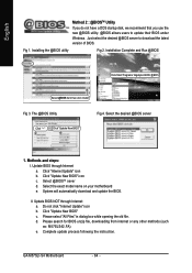
... use the new @BIOS utility. @BIOS allows users to download the latest version of BIOS. Installation Complete and Run @BIOS Click Start/ Programs/ Gigabyte/ BIOS/ @BIOS Select @BIOS item than click Install Fig 3. Methods and steps: I. Update BIOS through Internet: a. Select the exact model name on your motherboard e. GA-M57SLI-S4 Motherboard - 64 - Fig 1. The @BIOS Utility Fig 4. Select @BIOSTM sever d. Do not click "Internet Update" icon b. Just select the desired @BIOS server to update their BIOS under Windows. II. Complete update...
... use the new @BIOS utility. @BIOS allows users to download the latest version of BIOS. Installation Complete and Run @BIOS Click Start/ Programs/ Gigabyte/ BIOS/ @BIOS Select @BIOS item than click Install Fig 3. Methods and steps: I. Update BIOS through Internet: a. Select the exact model name on your motherboard e. GA-M57SLI-S4 Motherboard - 64 - Fig 1. The @BIOS Utility Fig 4. Select @BIOSTM sever d. Do not click "Internet Update" icon b. Just select the desired @BIOS server to update their BIOS under Windows. II. Complete update...
Manual
Page 72
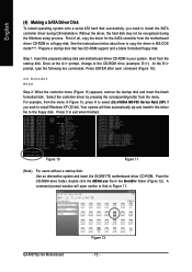
... a SATA Driver Disk To install operating system onto a serial ATA hard disk successfully, you wish to install Windows XP (32-bit). Press 0 to install the SATA controller driver during the Windows setup process. From the CD-ROM drive folder, double click the MENU.exe file in Figure 13, press H to select (H) nVIDIA MCP55 Series Raid (XP) if you need to exit when finished. For example, from the motherboard driver CD-ROM to the CD-ROM drive (example...
... a SATA Driver Disk To install operating system onto a serial ATA hard disk successfully, you wish to install Windows XP (32-bit). Press 0 to install the SATA controller driver during the Windows setup process. From the CD-ROM drive folder, double click the MENU.exe file in Figure 13, press H to select (H) nVIDIA MCP55 Series Raid (XP) if you need to exit when finished. For example, from the motherboard driver CD-ROM to the CD-ROM drive (example...

Manual
Page 73
... Step 2: When a screen similar to install Windows 2000/XP onto your SATA hard drive with the SATA driver. English (5) Installing SATA controller driver during OS installation Now that you have prepared the SATA driver disk and configured BIOS settings, you are ready to that below appears, insert the floppy disk containing the SATA driver and press S (Figure 14). Step 1: Restart your system, or you have any device support disks from the Windows 2000/XP Setup disk and press F6...
... Step 2: When a screen similar to install Windows 2000/XP onto your SATA hard drive with the SATA driver. English (5) Installing SATA controller driver during OS installation Now that you have prepared the SATA driver disk and configured BIOS settings, you are ready to that below appears, insert the floppy disk containing the SATA driver and press S (Figure 14). Step 1: Restart your system, or you have any device support disks from the Windows 2000/XP Setup disk and press F6...
Manual
Page 75
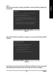
... port of the Setup program prepares Microsoft(R) Windows (R) XP to Setup. To set up Windows XP now, press ENTER. To repair a Windows XP installation using Recovery Console, press R. English Step 4: When the next screen (Figure 17) appears, press ENTER to continue the SATA driver installation from a mass storage device manufacturer, press S. * If you can proceed with the Windows 2000/XP installation. To quit Setup without installing Windows XP, press F3. Windows Setup Setup will not have any device support disks...
... port of the Setup program prepares Microsoft(R) Windows (R) XP to Setup. To set up Windows XP now, press ENTER. To repair a Windows XP installation using Recovery Console, press R. English Step 4: When the next screen (Figure 17) appears, press ENTER to continue the SATA driver installation from a mass storage device manufacturer, press S. * If you can proceed with the Windows 2000/XP installation. To quit Setup without installing Windows XP, press F3. Windows Setup Setup will not have any device support disks...

Manual
Page 81
.... AWARD BIOS Beep Codes 1 short: System boots successfully 2 short: CMOS setting error 1 long 1 short: DRAM or M/B error 1 long 2 short: Monitor or display card error 1 long 3 short: Keyboard error 1 long 9 short: BIOS ROM error Continuous long beeps: DRAM error Continuous short beeps: Power error - 81 - If your board has a Clear CMOS jumper, please refer to MB again and turn on after system boots up the speaker to clear CMOS. Please refer to enter BIOS and load Fail-Safe Defaults(or load Optimized Defaults). 7. What do these options. Why? Connect power cord to the Clear CMOS...
.... AWARD BIOS Beep Codes 1 short: System boots successfully 2 short: CMOS setting error 1 long 1 short: DRAM or M/B error 1 long 2 short: Monitor or display card error 1 long 3 short: Keyboard error 1 long 9 short: BIOS ROM error Continuous long beeps: DRAM error Continuous short beeps: Power error - 81 - If your board has a Clear CMOS jumper, please refer to MB again and turn on after system boots up the speaker to clear CMOS. Please refer to enter BIOS and load Fail-Safe Defaults(or load Optimized Defaults). 7. What do these options. Why? Connect power cord to the Clear CMOS...


