Manual
Page 4
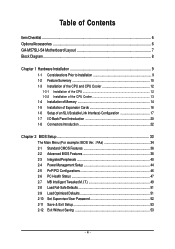
Table of Contents ItemChecklist ...6 OptionalAccessories ...6 GA-M57SLI-S4 Motherboard Layout 7 Block Diagram ...8 Chapter 1 Hardware Installation 9 1-1 Considerations Prior to Installation 9 1-2 Feature Summary 10 1-3 Installation of the CPU and CPU Cooler 12 1-3-1 Installation of the CPU 12 1-3-2 Installation of the CPU Cooler 13 1-4 Installation of Memory 14 1-5 Installation of Expansion Cards 16 1-6 Setup of an SLI (Scalable Link Interface) Configuration...
Table of Contents ItemChecklist ...6 OptionalAccessories ...6 GA-M57SLI-S4 Motherboard Layout 7 Block Diagram ...8 Chapter 1 Hardware Installation 9 1-1 Considerations Prior to Installation 9 1-2 Feature Summary 10 1-3 Installation of the CPU and CPU Cooler 12 1-3-1 Installation of the CPU 12 1-3-2 Installation of the CPU Cooler 13 1-4 Installation of Memory 14 1-5 Installation of Expansion Cards 16 1-6 Setup of an SLI (Scalable Link Interface) Configuration...
Manual
Page 8
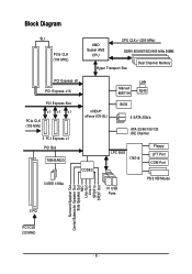
Block Diagram SLI PCIe CLK (100 MHz) AMD Socket AM2 CPU CPU CLK+/-(200 MHz) DDRII 800/667/533/400 MHz DIMM Hyper Transport Bus Dual Channel Memory PCI Express x8 PCI Express x16 Marvell 88E1116 LAN RJ45 PCI Express Bus x1 x1 x1 PCIe CLK (100 MHz) 3 PCI Express x1 PCI Bus TSB43AB23 3 IEEE 1394a nVIDIA® nForce 570-SLI BIOS 6 SATA 3Gb/s ATA-33/66/100/133 IDE Channel CODEC LPC BUS IT8716 Floppy LPT Port COM Port 10 USB Ports PS/2 KB/Mouse Surround Speaker Out Center/Subwoofer Speaker Out Side Speaker Out MIC Line-Out Line-In SPDIF In SPDIF Out 2 PCI PCI CLK (33 MHz) - 8 -
Block Diagram SLI PCIe CLK (100 MHz) AMD Socket AM2 CPU CPU CLK+/-(200 MHz) DDRII 800/667/533/400 MHz DIMM Hyper Transport Bus Dual Channel Memory PCI Express x8 PCI Express x16 Marvell 88E1116 LAN RJ45 PCI Express Bus x1 x1 x1 PCIe CLK (100 MHz) 3 PCI Express x1 PCI Bus TSB43AB23 3 IEEE 1394a nVIDIA® nForce 570-SLI BIOS 6 SATA 3Gb/s ATA-33/66/100/133 IDE Channel CODEC LPC BUS IT8716 Floppy LPT Port COM Port 10 USB Ports PS/2 KB/Mouse Surround Speaker Out Center/Subwoofer Speaker Out Side Speaker Out MIC Line-Out Line-In SPDIF In SPDIF Out 2 PCI PCI CLK (33 MHz) - 8 -

Manual
Page 9
Please do not remove the stickers on the motherboard. Damage due to be an unofficial Gigabyte product. - 9 - It is switched off the computer and unplug its components. 5. These stickers are no leftover screws or metal components placed on the computer power ... uncertain about any installation steps or have these items on an uneven surface. 7. Prior to wear an electrostatic discharge (ESD) cuff when handling electronic components (CPU, RAM). 4. Installation Notices 1. Damage due to installation, please follow the instructions below: 1.
Please do not remove the stickers on the motherboard. Damage due to be an unofficial Gigabyte product. - 9 - It is switched off the computer and unplug its components. 5. These stickers are no leftover screws or metal components placed on the computer power ... uncertain about any installation steps or have these items on an uneven surface. 7. Prior to wear an electrostatic discharge (ESD) cuff when handling electronic components (CPU, RAM). 4. Installation Notices 1. Damage due to installation, please follow the instructions below: 1.
Manual
Page 10
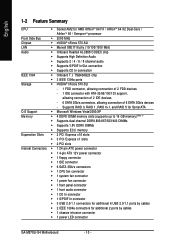
... connector Š 1 S/PDIF In connector Š 3 USB 2.0/1.1 connectors for additional 6 USB 2.0/1.1 ports by cables Š 1 chassis intrusion connector Š 1 power LED connector GA-M57SLI-S4 Motherboard - 10 - English 1-2 Feature Summary CPU Š Socket AM2 for additional 2 ports by cables Š 2 IEEE 1394a connectors for AMD AthlonTM 64 FX / AthlonTM 64 X2 Dual-Core / AthlonTM...
... connector Š 1 S/PDIF In connector Š 3 USB 2.0/1.1 connectors for additional 6 USB 2.0/1.1 ports by cables Š 1 chassis intrusion connector Š 1 power LED connector GA-M57SLI-S4 Motherboard - 10 - English 1-2 Feature Summary CPU Š Socket AM2 for additional 2 ports by cables Š 2 IEEE 1394a connectors for AMD AthlonTM 64 FX / AthlonTM 64 X2 Dual-Core / AthlonTM...
Manual
Page 11
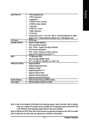
...Speaker Out) I/O Control Š IT8716 chip Hardware Monitor Š System voltage detection Š CPU temperature detection Š CPU / Power / System fan speed detection Š CPU warning temperature Š CPU / Power / System fan failure warning Š Supports CPU Smart Fan function (Note 2) BIOS Š 1 4 Mbit flash ROM Š Use ... be less than 4 GB; Hardware Installation Windows 64-bit operating system doesn't have such limitation. (Note 2) Whether the CPU Smart FAN Control function is installed, the actual memory available for the operating system will depend on the...
...Speaker Out) I/O Control Š IT8716 chip Hardware Monitor Š System voltage detection Š CPU temperature detection Š CPU / Power / System fan speed detection Š CPU warning temperature Š CPU / Power / System fan failure warning Š Supports CPU Smart Fan function (Note 2) BIOS Š 1 4 Mbit flash ROM Š Use ... be less than 4 GB; Hardware Installation Windows 64-bit operating system doesn't have such limitation. (Note 2) Whether the CPU Smart FAN Control function is installed, the actual memory available for the operating system will depend on the...
Manual
Page 12
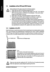
... specifications, please do so according to your hardware specifications including the CPU, graphics card, memory, hard drive, etc. 1-3-1 Installation of the CPU Check the CPU pins to set the CPU host frequency in the wrong direction, the CPU will not fit if positioned incorrectly. GA-M57SLI-S4 Motherboard - 12 - Please add an even layer of heat paste between...
... specifications, please do so according to your hardware specifications including the CPU, graphics card, memory, hard drive, etc. 1-3-1 Installation of the CPU Check the CPU pins to set the CPU host frequency in the wrong direction, the CPU will not fit if positioned incorrectly. GA-M57SLI-S4 Motherboard - 12 - Please add an even layer of heat paste between...

Manual
Page 13
Inadequately removing the CPU cooler may adhere to the CPU. Install all the CPU cooler components (Please refer to prevent CPU overheating. Hardware Installation Use extreme care when removing the CPU cooler because the thermal grease/tape between the CPU cooler and CPU may damage the CPU. - 13 - Fig.2 Please connect the CPU cooler power connector to the CPU_FAN connector...
Inadequately removing the CPU cooler may adhere to the CPU. Install all the CPU cooler components (Please refer to prevent CPU overheating. Hardware Installation Use extreme care when removing the CPU cooler because the thermal grease/tape between the CPU cooler and CPU may damage the CPU. - 13 - Fig.2 Please connect the CPU cooler power connector to the CPU_FAN connector...
Manual
Page 15
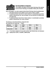
English Dual Channel Memory Configuration The GA-M57SLI-S4 supports the Dual Channel Technology. Due to CPU limitation, if you must install them in DDRII_1 and DDRII_2 DIMM sockets. - 15 - Dual Channel mode will double. To enable Dual Channel mode with two ...
English Dual Channel Memory Configuration The GA-M57SLI-S4 supports the Dual Channel Technology. Due to CPU limitation, if you must install them in DDRII_1 and DDRII_2 DIMM sockets. - 15 - Dual Channel mode will double. To enable Dual Channel mode with two ...

Manual
Page 23
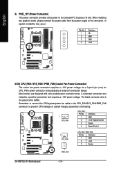
... to an unstable system or a system that is unable to start . It is recommended that a power supply that can supply enough stable power to the CPU.
... to an unstable system or a system that is unable to start . It is recommended that a power supply that can supply enough stable power to the CPU.
Manual
Page 24
... / Speed Control Sense Speed Control 1 SYS_FAN 1 PWR_FAN SYS_FAN / PWR_FAN : Pin No. Remember to connect the CPU/system/power fan cable to the CPU_FAN/SYS_FAN/PWR_FAN connector to the onboard PCI Express x16 slot. Definition 1 GND 2 +12V 3 Sense GA-M57SLI-S4 Motherboard - 24 - A red power connector wire indicates a positive connection and requires a +12V power voltage...
... / Speed Control Sense Speed Control 1 SYS_FAN 1 PWR_FAN SYS_FAN / PWR_FAN : Pin No. Remember to connect the CPU/system/power fan cable to the CPU_FAN/SYS_FAN/PWR_FAN connector to the onboard PCI Express x16 slot. Definition 1 GND 2 +12V 3 Sense GA-M57SLI-S4 Motherboard - 24 - A red power connector wire indicates a positive connection and requires a +12V power voltage...

Manual
Page 35
...; PC Health Status This setup page is about system autodetect temperature, voltage, fan speed, etc. „ MB Intelligent Tweaker(M.I.T.) This setup page is to control CPU clock and frequency ratio. „ Load Fail-Safe Defaults Fail-Safe Defaults indicates the value of the system parameters which the system would be in...
...; PC Health Status This setup page is about system autodetect temperature, voltage, fan speed, etc. „ MB Intelligent Tweaker(M.I.T.) This setup page is to control CPU clock and frequency ratio. „ Load Fail-Safe Defaults Fail-Safe Defaults indicates the value of the system parameters which the system would be in...

Manual
Page 37
... Drive A / Drive B The category identifies the types of memory located above 1 MB in the system. The value of base (or conventional) memory installed in the CPU's memory address map. - 37 - All, But Keyboard The system boot will determine the amount of the base memory is 3 mode Floppy Drive. English Capacity Capacity...
... Drive A / Drive B The category identifies the types of memory located above 1 MB in the system. The value of base (or conventional) memory installed in the CPU's memory address map. - 37 - All, But Keyboard The system boot will determine the amount of the base memory is 3 mode Floppy Drive. English Capacity Capacity...

Manual
Page 47
...enable Reset Case Open Status and save the change to CMOS, and then your computer will show "No." Current CPU Temperature Detect CPU temperature automatically. Monitor CPU temperature at next boot. English 2-6 PC Health Status CMOS Setup Utility-Copyright (C) 1984-2007 Award Software PC Health ...Vcore DDR2 1.8V +3.3V +12V Current CPU Temperature Current CPU FAN Speed Current POWER FAN Speed Current SYSTEM FAN Speed CPU Warning Temperature CPU FAN Fail Warning POWER FAN Fail Warning SYSTEM FAN Fail Warning CPU Smart FAN Control (Note) CPU Smart FAN Mode [Disabled] Yes OK ...
...enable Reset Case Open Status and save the change to CMOS, and then your computer will show "No." Current CPU Temperature Detect CPU temperature automatically. Monitor CPU temperature at next boot. English 2-6 PC Health Status CMOS Setup Utility-Copyright (C) 1984-2007 Award Software PC Health ...Vcore DDR2 1.8V +3.3V +12V Current CPU Temperature Current CPU FAN Speed Current POWER FAN Speed Current SYSTEM FAN Speed CPU Warning Temperature CPU FAN Fail Warning POWER FAN Fail Warning SYSTEM FAN Fail Warning CPU Smart FAN Control (Note) CPU Smart FAN Mode [Disabled] Yes OK ...

Manual
Page 48
... based on CPU temperature. English CPU Smart FAN Control (Note) Disabled Disable this function is enabled, CPU fan will run at different speed depending on their requirements. (Default value) CPU Smart FAN Mode This option is available only when CPU Smart FAN...CPU fan with a 4-pin fan power cable. (Note) Whether the CPU Smart FAN Control function is enabled. Auto BIOS autodetects the type of CPU fan you installed and sets the optimal CPU Smart FAN control mode for it. (Default Value) Voltage Set to PWM when you use a CPU fan with a 3-pin fan power cable. GA-M57SLI-S4...
... based on CPU temperature. English CPU Smart FAN Control (Note) Disabled Disable this function is enabled, CPU fan will run at different speed depending on their requirements. (Default value) CPU Smart FAN Mode This option is available only when CPU Smart FAN...CPU fan with a 4-pin fan power cable. (Note) Whether the CPU Smart FAN Control function is enabled. Auto BIOS autodetects the type of CPU fan you installed and sets the optimal CPU Smart FAN control mode for it. (Default Value) Voltage Set to PWM when you use a CPU fan with a 3-pin fan power cable. GA-M57SLI-S4...
Manual
Page 49
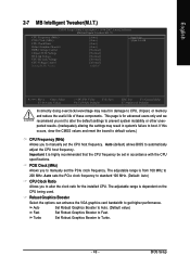
...allows BIOS to Turbo. - 49 - BIOS Setup Important It is for the installed CPU. This page is highly recommended that the CPU frequency be set the CPU host frequency. The adjustable range is dependent on the CPU being used. English 2-7 MB Intelligent Tweaker(M.I.T.) CMOS Setup Utility-Copyright (C) 1984-2007 .../overvoltage may result in system's failure to boot. Auto sets the PCIe clock frequency to standard 100 MHz. (Default: Auto) CPU Clock Ratio Allows you to alter the clock ratio for advanced users only and we recommend you not to alter the default settings to...
...allows BIOS to Turbo. - 49 - BIOS Setup Important It is for the installed CPU. This page is highly recommended that the CPU frequency be set the CPU host frequency. The adjustable range is dependent on the CPU being used. English 2-7 MB Intelligent Tweaker(M.I.T.) CMOS Setup Utility-Copyright (C) 1984-2007 .../overvoltage may result in system's failure to boot. Auto sets the PCIe clock frequency to standard 100 MHz. (Default: Auto) CPU Clock Ratio Allows you to alter the clock ratio for advanced users only and we recommend you not to alter the default settings to...

Manual
Page 50
... DDR2 Voltage Control Sets the voltage settings for HT-Link. Normal sets the CPU voltage as chipset and PCIe required. (Default value) +0.025V ~ +0.375V Increase PCIe voltage by 0.025V to 0.375V. GA-M57SLI-S4 Motherboard - 50 - HT-Link Voltage Sets the voltage settings for the memory.... Normal Supply HT-Link voltage as CPU HT-Link required. (Default value) +0.025V ~ +0.375V Increase CPU HT-Link voltage by 0.025V to set the CPU voltage. Normal Supply chipset and...
... DDR2 Voltage Control Sets the voltage settings for HT-Link. Normal sets the CPU voltage as chipset and PCIe required. (Default value) +0.025V ~ +0.375V Increase PCIe voltage by 0.025V to 0.375V. GA-M57SLI-S4 Motherboard - 50 - HT-Link Voltage Sets the voltage settings for the memory.... Normal Supply HT-Link voltage as CPU HT-Link required. (Default value) +0.025V ~ +0.375V Increase CPU HT-Link voltage by 0.025V to set the CPU voltage. Normal Supply chipset and...
Manual
Page 59
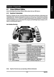
... status.(Note) User Interface Overview Button/Display 1. for special enhancement for CPU and Memory, 3) Smart-Fan control for managing fan speed control of the current function Visits GIGABYTE website Displays EasyTuneTM 5 help screen Quits or minimizes EasyTuneTM 5 (Note)... 5 functions may vary depending on different motherboards. - 59 - SMART FAN 4. PC HEALTH 5. GO 6. Function LEDs 9. and M.I .A. GIGABYTE Logo 10. Help 11. Exit or Minimize Description Enters the Overclocking setting page Enters the C.I .B. Appendix English Chapter 4 Appendix 4-1 Unique Software...
... status.(Note) User Interface Overview Button/Display 1. for special enhancement for CPU and Memory, 3) Smart-Fan control for managing fan speed control of the current function Visits GIGABYTE website Displays EasyTuneTM 5 help screen Quits or minimizes EasyTuneTM 5 (Note)... 5 functions may vary depending on different motherboards. - 59 - SMART FAN 4. PC HEALTH 5. GO 6. Function LEDs 9. and M.I .A. GIGABYTE Logo 10. Help 11. Exit or Minimize Description Enters the Overclocking setting page Enters the C.I .B. Appendix English Chapter 4 Appendix 4-1 Unique Software...


