
Manual
Page 4
Table of Contents ItemChecklist ...6 OptionalAccessories ...6 GA-M55plus-S3G (rev. 3.0) Motherboard Layout 7 Block Diagram ...8 Chapter 1 Hardware Installation 9 1-1 Considerations Prior to Installation 9 1-2 Feature Summary 10 1-3 Installation of the CPU and CPU Cooler 12 1-3-1 Installation of the CPU ...
Table of Contents ItemChecklist ...6 OptionalAccessories ...6 GA-M55plus-S3G (rev. 3.0) Motherboard Layout 7 Block Diagram ...8 Chapter 1 Hardware Installation 9 1-1 Considerations Prior to Installation 9 1-2 Feature Summary 10 1-3 Installation of the CPU and CPU Cooler 12 1-3-1 Installation of the CPU ...
Manual
Page 7
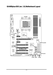
GA-M55plus-S3G (rev. 3.0) Motherboard Layout KB_MS Socket AM2 ATX COMA LPT VGA USB USB 1394 LAN ATX_12V AUDIO CPU_FAN F_AUDIO PCIE_1 Marvell 88E1116 nVIDIA® GeFore 6150 PCIE_16 DDRII_1 DDRII_2 DDRII_3 DDRII_4 CODEC PCIE_2 PCI1 PCI2 BATTERY BIOS nVIDIA® nForce 430 SATAII2_3 CD_IN SPDIF_IO PCI3 GA-M55plus-S3G TSB43AB23 IT8716 REV: 3.0 PCI4 CI SATAII0_1 IDE1 IDE2 F2_1394 PWR_LED FDD F1_1394 F_USB1 F_USB2 F_PANEL CLR_CMOS SYS_FAN - 7 -
GA-M55plus-S3G (rev. 3.0) Motherboard Layout KB_MS Socket AM2 ATX COMA LPT VGA USB USB 1394 LAN ATX_12V AUDIO CPU_FAN F_AUDIO PCIE_1 Marvell 88E1116 nVIDIA® GeFore 6150 PCIE_16 DDRII_1 DDRII_2 DDRII_3 DDRII_4 CODEC PCIE_2 PCI1 PCI2 BATTERY BIOS nVIDIA® nForce 430 SATAII2_3 CD_IN SPDIF_IO PCI3 GA-M55plus-S3G TSB43AB23 IT8716 REV: 3.0 PCI4 CI SATAII0_1 IDE1 IDE2 F2_1394 PWR_LED FDD F1_1394 F_USB1 F_USB2 F_PANEL CLR_CMOS SYS_FAN - 7 -
Manual
Page 10
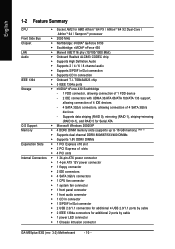
... connection of 4 SATA 3Gb/s devices - English 1-2 Feature Summary CPU Š Socket AM2 for additional 2 ports by cable Š 1 power LED connector Š 1 Chassis Intrusion connector GA-M55plus-S3G (rev. 3.0) Motherboard - 10 - Supports data striping (RAID 0), mirroring (RAID 1), striping+mirroring (RAID 0+1), and RAID 5 for Serial ATA O.S Support Š Microsoft Windows 2000/XP Memory Š 4 DDRII DIMM...
... connection of 4 SATA 3Gb/s devices - English 1-2 Feature Summary CPU Š Socket AM2 for additional 2 ports by cable Š 1 power LED connector Š 1 Chassis Intrusion connector GA-M55plus-S3G (rev. 3.0) Motherboard - 10 - Supports data striping (RAID 0), mirroring (RAID 1), striping+mirroring (RAID 0+1), and RAID 5 for Serial ATA O.S Support Š Microsoft Windows 2000/XP Memory Š 4 DDRII DIMM...
Manual
Page 12
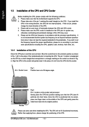
...it into place. Please use , otherwise overheating and permanent damage of the CPU and gently press the metal lever back into its original position. GA-M55plus-S3G (rev. 3.0) Motherboard - 12 - If you install the CPU in Fig. 2. Once the CPU is designated on the CPU by a small triangle that corresponds ... pins fit perfectly into the socket. If you wish to set beyond the proper specifications, please do so according to see that the motherboard supports the CPU. 2. Please make sure that none are bent. It is installed on the CPU prior to a triangle marking on ...
...it into place. Please use , otherwise overheating and permanent damage of the CPU and gently press the metal lever back into its original position. GA-M55plus-S3G (rev. 3.0) Motherboard - 12 - If you install the CPU in Fig. 2. Once the CPU is designated on the CPU by a small triangle that corresponds ... pins fit perfectly into the socket. If you wish to set beyond the proper specifications, please do so according to see that the motherboard supports the CPU. 2. Please make sure that none are bent. It is installed on the CPU prior to a triangle marking on ...
Manual
Page 14
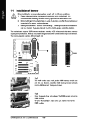
... power is switched off to remove the DIMM module. A memory module can only fit in one direction. Then push it down. GA-M55plus-S3G (rev. 3.0) Motherboard - 14 - Please make sure that they can differ with the following conditions: 1. If you wish to prevent hardware damage. 3. The... motherboard supports DDRII memory modules, whereby BIOS will automatically detect memory capacity and specifications. Fig.2 Close the plastic clip at both edges of...
... power is switched off to remove the DIMM module. A memory module can only fit in one direction. Then push it down. GA-M55plus-S3G (rev. 3.0) Motherboard - 14 - Please make sure that they can differ with the following conditions: 1. If you wish to prevent hardware damage. 3. The... motherboard supports DDRII memory modules, whereby BIOS will automatically detect memory capacity and specifications. Fig.2 Close the plastic clip at both edges of...
Manual
Page 16
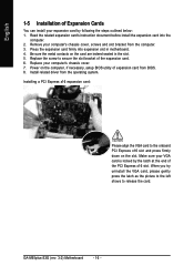
... uninstall the VGA card, please gently press the latch as the picture to the left shows to secure the slot bracket of the expansion card. 6. GA-M55plus-S3G (rev. 3.0) Motherboard - 16 - Installing a PCI Express x16 expansion card: Please align the VGA card to the onboard PCI Express x16 slot and press firmly down on the...
... uninstall the VGA card, please gently press the latch as the picture to the left shows to secure the slot bracket of the expansion card. 6. GA-M55plus-S3G (rev. 3.0) Motherboard - 16 - Installing a PCI Express x16 expansion card: Please align the VGA card to the onboard PCI Express x16 slot and press firmly down on the...
Manual
Page 18
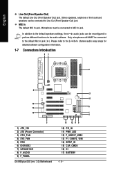
... for detailed software configuration information. 1-7 Connectors Introduction 31 2 8 17 15 10 14 6 16 7 4 5 1) ATX_12V 2) ATX (Power Connector) 3) CPU_FAN 4) SYS_FAN 5) FDD 6) IDE1/IDE2 7) SATAII0/1/2/3 8) F_AUDIO 9) F_PANEL GA-M55plus-S3G (rev. 3.0) Motherboard 13 12 11 9 10) CD_IN 11) PWR_LED 12) F_USB1/F_USB2 13) F1_1394/F2_1394 14) SPDIF_IO 15) CLR_CMOS 16) CI 17) BATTERY - 18 - In addition to...
... for detailed software configuration information. 1-7 Connectors Introduction 31 2 8 17 15 10 14 6 16 7 4 5 1) ATX_12V 2) ATX (Power Connector) 3) CPU_FAN 4) SYS_FAN 5) FDD 6) IDE1/IDE2 7) SATAII0/1/2/3 8) F_AUDIO 9) F_PANEL GA-M55plus-S3G (rev. 3.0) Motherboard 13 12 11 9 10) CD_IN 11) PWR_LED 12) F_USB1/F_USB2 13) F1_1394/F2_1394 14) SPDIF_IO 15) CLR_CMOS 16) CI 17) BATTERY - 18 - In addition to...
Manual
Page 20
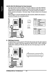
... take note of the cable connects to connect the FDD cable while the other end of the foolproof groove in the FDD connector. 33 1 34 2 GA-M55plus-S3G (rev. 3.0) Motherboard - 20 -
... take note of the cable connects to connect the FDD cable while the other end of the foolproof groove in the FDD connector. 33 1 34 2 GA-M55plus-S3G (rev. 3.0) Motherboard - 20 -
Manual
Page 22
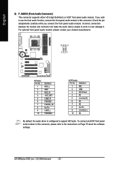
... Pin LINE2_L FSENSE2 AC'97 Audio: Pin No. Incorrect connection between the module and connector will make the audio device unable to support HD Audio. GA-M55plus-S3G (rev. 3.0) Motherboard - 22 - If you connect the front panel audio module. Definition 1 MIC 2 GND 3 MIC Power 4 NC 5 Line Out (R) 6 NC 7 NC 8 No Pin 9 Line Out (L) 10 NC...
... Pin LINE2_L FSENSE2 AC'97 Audio: Pin No. Incorrect connection between the module and connector will make the audio device unable to support HD Audio. GA-M55plus-S3G (rev. 3.0) Motherboard - 22 - If you connect the front panel audio module. Definition 1 MIC 2 GND 3 MIC Power 4 NC 5 Line Out (R) 6 NC 7 NC 8 No Pin 9 Line Out (L) 10 NC...
Manual
Page 24
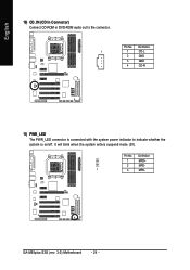
Pin No. Definition 1 1 CD-L 2 GND 3 GND 4 CD-R 11) PWR_LED The PWR_LED connector is on/off. It will blink when the system enters suspend mode (S1). Definition 1 MPD+ 2 MPD- 1 3 MPD- English 10) CD_IN (CD In Connector) Connect CD-ROM or DVD-ROM audio out to indicate whether the system is connected with the system power indicator to the connector. GA-M55plus-S3G (rev. 3.0) Motherboard - 24 - Pin No.
Pin No. Definition 1 1 CD-L 2 GND 3 GND 4 CD-R 11) PWR_LED The PWR_LED connector is on/off. It will blink when the system enters suspend mode (S1). Definition 1 MPD+ 2 MPD- 1 3 MPD- English 10) CD_IN (CD In Connector) Connect CD-ROM or DVD-ROM audio out to indicate whether the system is connected with the system power indicator to the connector. GA-M55plus-S3G (rev. 3.0) Motherboard - 24 - Pin No.
Manual
Page 26
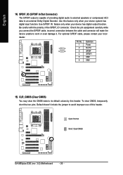
... cable, incorrect connection between the cable and connector will make the device unable to its default values by this header. Open: Normal Short: Clear CMOS GA-M55plus-S3G (rev. 3.0) Motherboard - 26 - For optional S/PDIF cable, please contact your local dealer. 1 2 5 6 Pin No. 1 2 3 4 5 6 Definition Power No Pin SPDIF SPDIFI GND GND 15) CLR_CMOS (Clear CMOS) You...
... cable, incorrect connection between the cable and connector will make the device unable to its default values by this header. Open: Normal Short: Clear CMOS GA-M55plus-S3G (rev. 3.0) Motherboard - 26 - For optional S/PDIF cable, please contact your local dealer. 1 2 5 6 Pin No. 1 2 3 4 5 6 Definition Power No Pin SPDIF SPDIFI GND GND 15) CLR_CMOS (Clear CMOS) You...

Manual
Page 28
English GA-M55plus-S3G (rev. 3.0) Motherboard - 28 -
English GA-M55plus-S3G (rev. 3.0) Motherboard - 28 -
Manual
Page 30
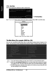
... Type... 1. The BIOS Setup menus described in the BIOS Setup when somehow the system is not stable as figure below) will appear on cards) device. GA-M55PLUS-S3G D3 . . . . :BIOS Setup/Q-Flash, : Xpress Recovery2, :For Boot Menu 10/25/2006-C51-MCP51-6A61HG0MC-00 :Boot Menu Use < > or < ... the items and press to exit this chapter are for reference only and may differ from the exact settings for your motherboard. GA-M55plus-S3G (rev. 3.0) Motherboard - 30 - Select the Load Optimized Defaults item in this menu. English : Boot Menu Select boot sequence for onboard (or add-...
... Type... 1. The BIOS Setup menus described in the BIOS Setup when somehow the system is not stable as figure below) will appear on cards) device. GA-M55PLUS-S3G D3 . . . . :BIOS Setup/Q-Flash, : Xpress Recovery2, :For Boot Menu 10/25/2006-C51-MCP51-6A61HG0MC-00 :Boot Menu Use < > or < ... the items and press to exit this chapter are for reference only and may differ from the exact settings for your motherboard. GA-M55plus-S3G (rev. 3.0) Motherboard - 30 - Select the Load Optimized Defaults item in this menu. English : Boot Menu Select boot sequence for onboard (or add-...
Manual
Page 32
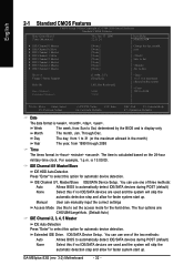
..., determined by the BIOS and is , , , . IDE Channel 0/1 Master/Slave IDE HDD Auto-Detection Press "Enter" to set the access mode for automatic device detection. GA-M55plus-S3G (rev. 3.0) Motherboard - 32 - Drive A Floppy 3 Mode Support Halt On Base Memory Extended Memory [1.44M, 3.5"] [Disabled] [All, But Keyboard] 640K 511M 1 to 31 (or maximum allowed in . Manual...
..., determined by the BIOS and is , , , . IDE Channel 0/1 Master/Slave IDE HDD Auto-Detection Press "Enter" to set the access mode for automatic device detection. GA-M55plus-S3G (rev. 3.0) Motherboard - 32 - Drive A Floppy 3 Mode Support Halt On Base Memory Extended Memory [1.44M, 3.5"] [Disabled] [All, But Keyboard] 640K 511M 1 to 31 (or maximum allowed in . Manual...
Manual
Page 34
... device priority by Floppy. Note that there will determine the floppy disk drive installed is 40 or 80 tracks. 360K type is 360K. (Default value) GA-M55plus-S3G (rev. 3.0) Motherboard - 34 - Use < > or < > to select a device, then press to move it up, or to move it is 40 or 80 tracks. First / Second / Third Boot...
... device priority by Floppy. Note that there will determine the floppy disk drive installed is 40 or 80 tracks. 360K type is 360K. (Default value) GA-M55plus-S3G (rev. 3.0) Motherboard - 34 - Use < > or < > to select a device, then press to move it up, or to move it is 40 or 80 tracks. First / Second / Third Boot...
Manual
Page 36
...] Enabled Enabled [Enabled] Enabled Enabled Item Help Menu Level` KLJI: Move Enter: Select F5: Previous Values +/-/PU/PD: Value F10: Save F6: Fail-Safe Defaults GA-M55plus-S3G (rev. 3.0) Motherboard - 36 -
...] Enabled Enabled [Enabled] Enabled Enabled Item Help Menu Level` KLJI: Move Enter: Select F5: Previous Values +/-/PU/PD: Value F10: Save F6: Fail-Safe Defaults GA-M55plus-S3G (rev. 3.0) Motherboard - 36 -
Manual
Page 38
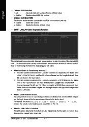
... a 10/100 Mbps hub, the Status fields of wires, the Status field will be the approximate distance to the fault or short. GA-M55plus-S3G (rev. 3.0) Motherboard - 38 - However, because Pair 4-5 and Pair 7-8 are not used in the figure above. 2. Disabled Disable this function. If... Previous Values +/-/PU/PD: Value F10: Save F6: Fail-Safe Defaults ESC: Exit F1: General Help F7: Optimized Defaults This motherboard incorporates cable diagnostic feature designed to the following information for diagnosing your LAN cable: When LAN Cable Is Functioning Normally... 1. If no...
... a 10/100 Mbps hub, the Status fields of wires, the Status field will be the approximate distance to the fault or short. GA-M55plus-S3G (rev. 3.0) Motherboard - 38 - However, because Pair 4-5 and Pair 7-8 are not used in the figure above. 2. Disabled Disable this function. If... Previous Values +/-/PU/PD: Value F10: Save F6: Fail-Safe Defaults ESC: Exit F1: General Help F7: Optimized Defaults This motherboard incorporates cable diagnostic feature designed to the following information for diagnosing your LAN cable: When LAN Cable Is Functioning Normally... 1. If no...
Manual
Page 40
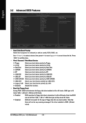
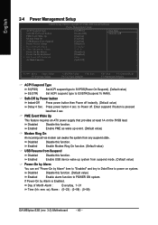
... Modem Ring On USB Resume from Suspend Power-On by Alarm x Day of Month Alarm : Everyday, 1~31 Time (hh: mm: ss) Alarm : (0~23) : (0~59) : (0~59) GA-M55plus-S3G (rev. 3.0) Motherboard - 40 - If Power-On by Alarm is pressed less than 4 sec. Enabled Enable Modem Ring On function. (Default value) USB Resume from Suspend Disabled Enabled...
... Modem Ring On USB Resume from Suspend Power-On by Alarm x Day of Month Alarm : Everyday, 1~31 Time (hh: mm: ss) Alarm : (0~23) : (0~59) : (0~59) GA-M55plus-S3G (rev. 3.0) Motherboard - 40 - If Power-On by Alarm is pressed less than 4 sec. Enabled Enable Modem Ring On function. (Default value) USB Resume from Suspend Disabled Enabled...

Manual
Page 42
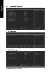
...) Set IRQ 3,4,5,7,9,10,11,12,14,15 to PCI 4. Auto assign IRQ to PCI 4. (Default value) Set IRQ 3,4,5,7,9,10,11,12,14,15 to PCI 2. GA-M55plus-S3G (rev. 3.0) Motherboard - 42 - Auto assign IRQ to PCI 3. (Default value) Set IRQ 3,4,5,7,9,10,11,12,14,15 to PCI 1. English 2-5 PnP/PCI Configurations CMOS Setup Utility-Copyright...
...) Set IRQ 3,4,5,7,9,10,11,12,14,15 to PCI 4. Auto assign IRQ to PCI 4. (Default value) Set IRQ 3,4,5,7,9,10,11,12,14,15 to PCI 2. GA-M55plus-S3G (rev. 3.0) Motherboard - 42 - Auto assign IRQ to PCI 3. (Default value) Set IRQ 3,4,5,7,9,10,11,12,14,15 to PCI 1. English 2-5 PnP/PCI Configurations CMOS Setup Utility-Copyright...
Manual
Page 44
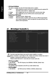
... these components. System Smart FAN Control Disabled Disable this function. (Default value) Enabled When this function is enabled. PWM Set to 200 MHz. (Default: Auto) GA-M55plus-S3G (rev. 3.0) Motherboard - 44 - Users can adjust the fan speed with a 4-pin fan power cable. CPU Frequency(MHz) 200~500 MHz Set CPU Frequency from 200 MHz to...
... these components. System Smart FAN Control Disabled Disable this function. (Default value) Enabled When this function is enabled. PWM Set to 200 MHz. (Default: Auto) GA-M55plus-S3G (rev. 3.0) Motherboard - 44 - Users can adjust the fan speed with a 4-pin fan power cable. CPU Frequency(MHz) 200~500 MHz Set CPU Frequency from 200 MHz to...


