
User Manual
Page 1
GA-K8N51GMF-9 AMD Socket 939 Processor Motherboard User's Manual Rev. 1004 12ME-51GMF9-1004R * The WEEE marking on the product indicates this product must not be disposed of with user's other household waste and must be handed over to a designated collection point for the recycling of waste electrical and electronic equipment!! * The WEEE marking applies only in European Union's member states.
GA-K8N51GMF-9 AMD Socket 939 Processor Motherboard User's Manual Rev. 1004 12ME-51GMF9-1004R * The WEEE marking on the product indicates this product must not be disposed of with user's other household waste and must be handed over to a designated collection point for the recycling of waste electrical and electronic equipment!! * The WEEE marking applies only in European Union's member states.

User Manual
Page 2
Motherboard GA-K8N51GMF-9 Sept. 29, 2005 Motherboard GA-K8N51GMF-9 Sept. 29, 2005
Motherboard GA-K8N51GMF-9 Sept. 29, 2005 Motherboard GA-K8N51GMF-9 Sept. 29, 2005
User Manual
Page 4
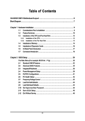
Table of Contents GA-K8N51GMF-9 Motherboard Layout 6 Block Diagram ...7 Chapter 1 Hardware Installation 9 1-1 Considerations Prior to Installation 9 1-2 Feature Summary 10 1-3 Installation of the CPU and Fan Heat Sink 12 1-3-1 Installation of the ...
Table of Contents GA-K8N51GMF-9 Motherboard Layout 6 Block Diagram ...7 Chapter 1 Hardware Installation 9 1-1 Considerations Prior to Installation 9 1-2 Feature Summary 10 1-3 Installation of the CPU and Fan Heat Sink 12 1-3-1 Installation of the ...

User Manual
Page 9
... circuits and components which can lead to damage to system components as well as a result of electrostatic discharge (ESD). Turning on the motherboard. Thus, prior to be an unofficial Gigabyte product. - 9 - Product determined to installation, please follow the instructions below: 1. Please verify that all cables and power connectors are uncertain about any...
... circuits and components which can lead to damage to system components as well as a result of electrostatic discharge (ESD). Turning on the motherboard. Thus, prior to be an unofficial Gigabyte product. - 9 - Product determined to installation, please follow the instructions below: 1. Please verify that all cables and power connectors are uncertain about any...
User Manual
Page 10
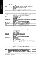
... architecture, a certain amount of memory size will instead be shown as 3.xxGB memory during system startup. Line Out (Front Speaker Out) ; Center/Subwoofer Speaker Out ; GA-K8N51GMF-9 Motherboard - 10 - Surround Speaker Out (Rear Speaker Out) ;
... architecture, a certain amount of memory size will instead be shown as 3.xxGB memory during system startup. Line Out (Front Speaker Out) ; Center/Subwoofer Speaker Out ; GA-K8N51GMF-9 Motherboard - 10 - Surround Speaker Out (Rear Speaker Out) ;
User Manual
Page 11
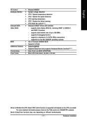
...supports a maximum of up to 300 MB/s - supports hot plugging function - For more detailed information please check at the FAQ section on GIGABYTE's website. (Note 3) EasyTune functions may vary depending on the CPU you install. supported on the Win 2000/XP operating systems Š...138; Micro ATX form factor; 24.4cm x 24.4cm (Note 2) Whether the CPU Smart FAN Control function is supported will depend on different motherboards. - 11 - English I/O Control Hardware Monitor Onboard SATA 3Gb/s RAID BIOS Additional Features Overclocking Form Factor Š Winbond W83627 Š System voltage...
...supports a maximum of up to 300 MB/s - supports hot plugging function - For more detailed information please check at the FAQ section on GIGABYTE's website. (Note 3) EasyTune functions may vary depending on the CPU you install. supported on the Win 2000/XP operating systems Š...138; Micro ATX form factor; 24.4cm x 24.4cm (Note 2) Whether the CPU Smart FAN Control function is supported will depend on different motherboards. - 11 - English I/O Control Hardware Monitor Onboard SATA 3Gb/s RAID BIOS Additional Features Overclocking Form Factor Š Winbond W83627 Š System voltage...
User Manual
Page 12
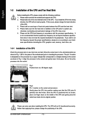
...position as shown in the wrong direction, the CPU will not fit if positioned incorrectly. Gently place the CPU into position making sure that the motherboard supports the CPU. 2. Fig.2 Pin 1 location on the socket as shown in accordance with the following conditions: 1. Once the CPU is designated..., place one indented corner of heat sink paste between the CPU and fan heat sink. 4. Do not force the processor into their holes. GA-K8N51GMF-9 Motherboard - 12 - It is installed on the middle of the CPU and gently press the metal lever back into place. The CPU will not ...
...position as shown in the wrong direction, the CPU will not fit if positioned incorrectly. Gently place the CPU into position making sure that the motherboard supports the CPU. 2. Fig.2 Pin 1 location on the socket as shown in accordance with the following conditions: 1. Once the CPU is designated..., place one indented corner of heat sink paste between the CPU and fan heat sink. 4. Do not force the processor into their holes. GA-K8N51GMF-9 Motherboard - 12 - It is installed on the middle of the CPU and gently press the metal lever back into place. The CPU will not ...

User Manual
Page 13
... 1-3-2 Installation of the Fan Heat Sink Fig.1 Before installing the fan heat sink, please first add an even layer of heat sink paste on the motherboard so that either thermal tape rather than heat sink paste be used for detailed installation instructions). Fig.2 Please connect the fan heat sink power connector...
... 1-3-2 Installation of the Fan Heat Sink Fig.1 Before installing the fan heat sink, please first add an even layer of heat sink paste on the motherboard so that either thermal tape rather than heat sink paste be used for detailed installation instructions). Fig.2 Please connect the fan heat sink power connector...
User Manual
Page 14
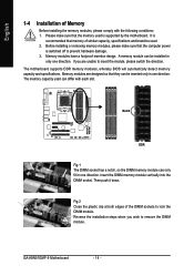
... DDR memory modules, whereby BIOS will automatically detect memory capacity and specifications. Memory modules are unable to lock the DIMM module. GA-K8N51GMF-9 Motherboard - 14 - English 1-4 Installation of Memory Before installing the memory modules, please comply with each slot. Memory modules have a foolproof insertion design. Please make sure that ...
... DDR memory modules, whereby BIOS will automatically detect memory capacity and specifications. Memory modules are unable to lock the DIMM module. GA-K8N51GMF-9 Motherboard - 14 - English 1-4 Installation of Memory Before installing the memory modules, please comply with each slot. Memory modules have a foolproof insertion design. Please make sure that ...

User Manual
Page 16
...3. Please align the VGA card to the onboard PCI Express x 16 slot and press firmly down on the card are indeed seated in motherboard. 4. Be sure the metal contacts on the slot. Make sure your expansion card by the small white-drawable bar. Install related driver ... card or to the left shows. Press the expansion card firmly into the computer. 2. Replace the screw to install/ uninstall the VGA card. GA-K8N51GMF-9 Motherboard - 16 - Read the related expansion card's instruction document before install the expansion card into expansion slot in the slot. 5. Power on the ...
...3. Please align the VGA card to the onboard PCI Express x 16 slot and press firmly down on the card are indeed seated in motherboard. 4. Be sure the metal contacts on the slot. Make sure your expansion card by the small white-drawable bar. Install related driver ... card or to the left shows. Press the expansion card firmly into the computer. 2. Replace the screw to install/ uninstall the VGA card. GA-K8N51GMF-9 Motherboard - 16 - Read the related expansion card's instruction document before install the expansion card into expansion slot in the slot. 5. Power on the ...

User Manual
Page 18
... configuration information. 1-7 Connectors Introduction 1 3 2 5 6 8 18 16 17 7 10 9 14 15 4 13 12 11 1) ATX_12V 2) ATX (Power Connector) 3) CPU_FAN 4) SYS_FAN 5) FDD 6) IDE1 / IDE2 7) SATAII0/1/2/3 8) F_AUDIO 9) F_PANEL GA-K8N51GMF-9 Motherboard 10) CD_IN 11) PWR_LED 12) F_USB1 / F_USB2 13) F1_1394 14) SPDIF_IO 15) COMA 16) CLR_CMOS 17) CI 18) BATTERY - 18 - Side Speaker Out The default...
... configuration information. 1-7 Connectors Introduction 1 3 2 5 6 8 18 16 17 7 10 9 14 15 4 13 12 11 1) ATX_12V 2) ATX (Power Connector) 3) CPU_FAN 4) SYS_FAN 5) FDD 6) IDE1 / IDE2 7) SATAII0/1/2/3 8) F_AUDIO 9) F_PANEL GA-K8N51GMF-9 Motherboard 10) CD_IN 11) PWR_LED 12) F_USB1 / F_USB2 13) F1_1394 14) SPDIF_IO 15) COMA 16) CLR_CMOS 17) CI 18) BATTERY - 18 - Side Speaker Out The default...

User Manual
Page 19
...is able to start . If you use a 24-pin ATX power supply, please remove the small cover on the power connector on the motherboard and connect tightly. Before connecting the power connector, please make sure that can withstand high power consumption be used that does not provide the ...required power, the result can lead to an unstable system or a system that is recommended that a power supply that all the components on the motherboard. English 1/2) ATX_12V/ATX (Power Connector) With the use of the power connector, the power supply can supply enough stable power to the CPU....
...is able to start . If you use a 24-pin ATX power supply, please remove the small cover on the power connector on the motherboard and connect tightly. Before connecting the power connector, please make sure that can withstand high power consumption be used that does not provide the ...required power, the result can lead to an unstable system or a system that is recommended that a power supply that all the components on the motherboard. English 1/2) ATX_12V/ATX (Power Connector) With the use of the power connector, the power supply can supply enough stable power to the CPU....

User Manual
Page 20
... voltage via a 3-pin power connector and possesses a foolproof connection design. Please remember to connect the power to the cooler to the pin1 position. 34 33 GA-K8N51GMF-9 Motherboard 2 1 - 20 - Caution! The black connector wire is used to the FDD drive. The types of the cable connects to connect the FDD cable while the...
... voltage via a 3-pin power connector and possesses a foolproof connection design. Please remember to connect the power to the cooler to the pin1 position. 34 33 GA-K8N51GMF-9 Motherboard 2 1 - 20 - Caution! The black connector wire is used to the FDD drive. The types of the cable connects to connect the FDD cable while the...
User Manual
Page 22
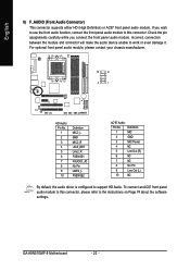
... connect an AC97 front panel audio module to the instructions on Page 74 about the software settings. If you connect the front panel audio module. GA-K8N51GMF-9 Motherboard - 22 - For optional front panel audio module, please contact your chassis manufacturer. 10 9 2 1 HD Audio: Pin No. 1 2 3 4 5 6 7 8 9 10 Definition MIC2_L GND MIC2_R -ACZ_DET Line2_R FSENSE1...
... connect an AC97 front panel audio module to the instructions on Page 74 about the software settings. If you connect the front panel audio module. GA-K8N51GMF-9 Motherboard - 22 - For optional front panel audio module, please contact your chassis manufacturer. 10 9 2 1 HD Audio: Pin No. 1 2 3 4 5 6 7 8 9 10 Definition MIC2_L GND MIC2_R -ACZ_DET Line2_R FSENSE1...

User Manual
Page 24
Pin No. It will blink when the system enters suspend mode. Definition 1 MPD+ 1 2 MPD- 3 MPD- Pin No. English 10) CD_IN (CD In Connector) Connect CD-ROM or DVD-ROM audio out to indicate whether the system is connect with the system power indicator to the connector. GA-K8N51GMF-9 Motherboard - 24 - Definition 1 1 CD-L 2 GND 3 GND 4 CD-R 11) PWR_LED PWR_LED is on/off.
Pin No. It will blink when the system enters suspend mode. Definition 1 MPD+ 1 2 MPD- 3 MPD- Pin No. English 10) CD_IN (CD In Connector) Connect CD-ROM or DVD-ROM audio out to indicate whether the system is connect with the system power indicator to the connector. GA-K8N51GMF-9 Motherboard - 24 - Definition 1 1 CD-L 2 GND 3 GND 4 CD-R 11) PWR_LED PWR_LED is on/off.

User Manual
Page 26
... local dealer. For optional SPDIF cable, please contact your nearest dealer for optional COMA cable. 2 10 1 9 Pin No. 1 2 3 4 5 6 7 8 9 10 Definition NDCDANSINA NSOUTA NDTRAGND NDSRANRTSANCTSANRIANo Pin GA-K8N51GMF-9 Motherboard - 26 - English 14) SPDIF_IO (SPDIF In/Out) The SPDIF output is capable of providing digital audio to external speakers or compressed AC3 data to work...
... local dealer. For optional SPDIF cable, please contact your nearest dealer for optional COMA cable. 2 10 1 9 Pin No. 1 2 3 4 5 6 7 8 9 10 Definition NDCDANSINA NSOUTA NDTRAGND NDSRANRTSANCTSANRIANo Pin GA-K8N51GMF-9 Motherboard - 26 - English 14) SPDIF_IO (SPDIF In/Out) The SPDIF output is capable of providing digital audio to external speakers or compressed AC3 data to work...

User Manual
Page 28
Dispose of explosion if battery is incorrectly replaced. GA-K8N51GMF-9 Motherboard - 28 - Replace only with the same or equivalent type recommended by the manufacturer. Turn OFF the computer and unplug the power cord. 2. Take out the ...
Dispose of explosion if battery is incorrectly replaced. GA-K8N51GMF-9 Motherboard - 28 - Replace only with the same or equivalent type recommended by the manufacturer. Turn OFF the computer and unplug the power cord. 2. Take out the ...

User Manual
Page 29
...Defaults Q-Flash utility System Information Save all the CMOS changes, only for Main Menu Main Menu The on the motherboard supplies the necessary power to select item Select Item Main Menu - Quit and not save the current BIOS ...to a disk in the CMOS SRAM of the motherboard. To exit the Help Window press . - 29 - When the power is a Windows-based utility that does not... is recommended that you wish to upgrade to a new BIOS, either Gigabyte's Q-Flash or @BIOS utility can enter the BIOS setup screen by pressing "Ctrl + F1".
...Defaults Q-Flash utility System Information Save all the CMOS changes, only for Main Menu Main Menu The on the motherboard supplies the necessary power to select item Select Item Main Menu - Quit and not save the current BIOS ...to a disk in the CMOS SRAM of the motherboard. To exit the Help Window press . - 29 - When the power is a Windows-based utility that does not... is recommended that you wish to upgrade to a new BIOS, either Gigabyte's Q-Flash or @BIOS utility can enter the BIOS setup screen by pressing "Ctrl + F1".

User Manual
Page 30
... the setting you enter Award BIOS CMOS Setup Utility, the Main Menu (as usual. This action makes the system reset to the default for your motherboard. GA-K8N51GMF-9 Motherboard - 30 - Use arrow keys to select among the items and press to accept or enter the sub-menu. The Main Menu (For example: BIOS Ver...
... the setting you enter Award BIOS CMOS Setup Utility, the Main Menu (as usual. This action makes the system reset to the default for your motherboard. GA-K8N51GMF-9 Motherboard - 30 - Use arrow keys to select among the items and press to accept or enter the sub-menu. The Main Menu (For example: BIOS Ver...
User Manual
Page 32
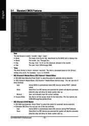
... only Month The month, Jan. The four options are used and the system will skip the automatic detection step and allow for automatic device detection. GA-K8N51GMF-9 Motherboard - 32 - IDE Channel 1 Master/Slave IDE HDD Auto-Detection Press "Enter" to select this if no IDE devices are used and the system will skip...
... only Month The month, Jan. The four options are used and the system will skip the automatic detection step and allow for automatic device detection. GA-K8N51GMF-9 Motherboard - 32 - IDE Channel 1 Master/Slave IDE HDD Auto-Detection Press "Enter" to select this if no IDE devices are used and the system will skip...


