
Manual
Page 3
..., transmitted, or published in this : "REV: X.X." For product-related information, check on our website at: http://www.gigabyte.com Identifying Your Motherboard Revision The revision number on your motherboard revision before updating motherboard BIOS, drivers, or when looking for technical information. Check your motherboard looks like this manual are legally registered to...
..., transmitted, or published in this : "REV: X.X." For product-related information, check on our website at: http://www.gigabyte.com Identifying Your Motherboard Revision The revision number on your motherboard revision before updating motherboard BIOS, drivers, or when looking for technical information. Check your motherboard looks like this manual are legally registered to...
Manual
Page 4
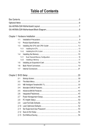
Table of Contents Box Contents...6 Optional Items...6 GA-H67MA-D2H Motherboard Layout 7 GA-H67MA-D2H Motherboard Block Diagram 8 Chapter 1 Hardware Installation 9 1-1 Installation Precautions 9 1-2 Product Specifications 10 1-3 Installing the CPU and CPU ... an Expansion Card 18 1-6 Back Panel Connectors 19 1-7 Internal Connectors 21 Chapter 2 BIOS Setup 29 2-1 Startup Screen 30 2-2 The Main Menu 31 2-3 MB Intelligent Tweaker(M.I.T 33 2-4 Standard CMOS Features 41 2-5 Advanced BIOS Features 43 2-6 Integrated Peripherals 45 2-7 Power Management Setup 48 2-8 PC Health Status ...
Table of Contents Box Contents...6 Optional Items...6 GA-H67MA-D2H Motherboard Layout 7 GA-H67MA-D2H Motherboard Block Diagram 8 Chapter 1 Hardware Installation 9 1-1 Installation Precautions 9 1-2 Product Specifications 10 1-3 Installing the CPU and CPU ... an Expansion Card 18 1-6 Back Panel Connectors 19 1-7 Internal Connectors 21 Chapter 2 BIOS Setup 29 2-1 Startup Screen 30 2-2 The Main Menu 31 2-3 MB Intelligent Tweaker(M.I.T 33 2-4 Standard CMOS Features 41 2-5 Advanced BIOS Features 43 2-6 Integrated Peripherals 45 2-7 Power Management Setup 48 2-8 PC Health Status ...

Manual
Page 5
... 56 3-4 Contact...57 3-5 System...57 3-6 Download Center 58 3-7 New Utilities...58 Chapter 4 Unique Features 59 4-1 Xpress Recovery2 59 4-2 BIOS Update Utilities 62 4-2-1 Updating the BIOS with the Q-Flash Utility 62 4-2-2 Updating the BIOS with the @BIOS Utility 65 4-3 EasyTune 6...66 4-4 Dynamic Energy Saver™ 2 67 4-5 Q-Share...69 4-6 Smart 6™ ...70 4-7 Auto Green...74 4-8 eXtreme...
... 56 3-4 Contact...57 3-5 System...57 3-6 Download Center 58 3-7 New Utilities...58 Chapter 4 Unique Features 59 4-1 Xpress Recovery2 59 4-2 BIOS Update Utilities 62 4-2-1 Updating the BIOS with the Q-Flash Utility 62 4-2-2 Updating the BIOS with the @BIOS Utility 65 4-3 EasyTune 6...66 4-4 Dynamic Energy Saver™ 2 67 4-5 Q-Share...69 4-6 Smart 6™ ...70 4-7 Auto Green...74 4-8 eXtreme...
Manual
Page 8
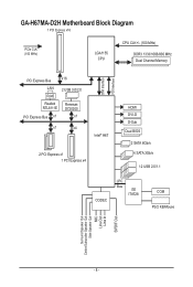
GA-H67MA-D2H Motherboard Block Diagram 1 PCI Express x16 PCIe CLK (100 MHz) LGA1155 CPU CPU CLK+/- (100 MHz) DDR3 1333/1066/800 MHz Dual Channel Memory PCI Express Bus x16 LAN 2 USB 3.0/2.0 RJ45 Realtek RTL8111E Renesas D720200 PCI Express Bus x1 x1 x1 x4 Intel® H67 2 PCI Express x1 1 PCI Express x4 DMI Interface FDI Interface HDMI DVI-D D-Sub Dual BIOS 2 SATA 6Gb/s 4 SATA 3Gb/s 12 USB 2.0/1.1 CODEC LPC Bus iTE IT8728 COM PS/2 KB/Mouse Surround Speaker Out Center/Subwoofer Speaker Out Side Speaker Out MIC Line Out Line In S/PDIF Out - 8 -
GA-H67MA-D2H Motherboard Block Diagram 1 PCI Express x16 PCIe CLK (100 MHz) LGA1155 CPU CPU CLK+/- (100 MHz) DDR3 1333/1066/800 MHz Dual Channel Memory PCI Express Bus x16 LAN 2 USB 3.0/2.0 RJ45 Realtek RTL8111E Renesas D720200 PCI Express Bus x1 x1 x1 x4 Intel® H67 2 PCI Express x1 1 PCI Express x4 DMI Interface FDI Interface HDMI DVI-D D-Sub Dual BIOS 2 SATA 6Gb/s 4 SATA 3Gb/s 12 USB 2.0/1.1 CODEC LPC Bus iTE IT8728 COM PS/2 KB/Mouse Surround Speaker Out Center/Subwoofer Speaker Out Side Speaker Out MIC Line Out Line In S/PDIF Out - 8 -
Manual
Page 11
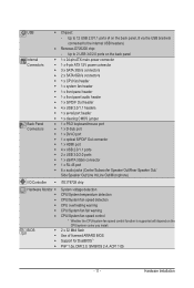
... Speaker Out/ Side Speaker Out/Line In/Line Out/Microphone) I/O Controller w iTE IT8728 chip Hardware Monitor w w w w w w BIOS w w w w System voltage detection CPU/System temperature detection CPU/System fan speed detection CPU overheating warning CPU/System fan fail warning CPU/System... (4 on the CPU/system cooler you install. 2 x 32 Mbit flash Use of licensed AWARD BIOS Support for DualBIOS™ PnP 1.0a, DMI 2.0, SM BIOS 2.4, ACPI 1.0b - 11 - USB w Chipset: - Up to the internal USB headers) w Renesas D720200 ...
... Speaker Out/ Side Speaker Out/Line In/Line Out/Microphone) I/O Controller w iTE IT8728 chip Hardware Monitor w w w w w w BIOS w w w w System voltage detection CPU/System temperature detection CPU/System fan speed detection CPU overheating warning CPU/System fan fail warning CPU/System... (4 on the CPU/system cooler you install. 2 x 32 Mbit flash Use of licensed AWARD BIOS Support for DualBIOS™ PnP 1.0a, DMI 2.0, SM BIOS 2.4, ACPI 1.0b - 11 - USB w Chipset: - Up to the internal USB headers) w Renesas D720200 ...
Manual
Page 12
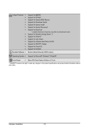
... model. Unique Features w w w w w w w w w w w w w w Bundled Software w Support for @BIOS Support for Q-Flash Support for Xpress BIOS Rescue Support for Download Center Support for Xpress Install Support for Xpress Recovery2 Support for Microsoft® Windows® 7/Vista/XP Form... Factor w Micro ATX Form Factor; 24.4cm x 21.1cm * GIGABYTE reserves ...
... model. Unique Features w w w w w w w w w w w w w w Bundled Software w Support for @BIOS Support for Q-Flash Support for Xpress BIOS Rescue Support for Download Center Support for Xpress Install Support for Xpress Recovery2 Support for Microsoft® Windows® 7/Vista/XP Form... Factor w Micro ATX Form Factor; 24.4cm x 21.1cm * GIGABYTE reserves ...

Manual
Page 16
...before installing the memory to install the memory: • Make sure that the motherboard supports the memory. It is installed, the BIOS will double the original memory bandwidth. Dual Channel mode cannot be installed in Dual Channel mode. 1. Hardware Installation - 16 - Enabling... Channel memory mode will automatically detect the specifications and capacity of the same capacity, brand, speed, and chips be used . (Go to GIGABYTE's website for optimum performance. When enabling Dual Channel mode with two memory modules, it is installed. 2. 1-4 Installing the Memory Read the...
...before installing the memory to install the memory: • Make sure that the motherboard supports the memory. It is installed, the BIOS will double the original memory bandwidth. Dual Channel mode cannot be installed in Dual Channel mode. 1. Hardware Installation - 16 - Enabling... Channel memory mode will automatically detect the specifications and capacity of the same capacity, brand, speed, and chips be used . (Go to GIGABYTE's website for optimum performance. When enabling Dual Channel mode with two memory modules, it is installed. 2. 1-4 Installing the Memory Read the...
Manual
Page 18
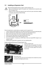
... slot. Carefully read the manual that supports your expansion card(s). 7. Make sure the metal contacts on your operating system. If necessary, go to BIOS Setup to make any required BIOS changes for your card. Make sure the card is fully inserted into the slot. 4. Hardware Installation - 18 - 1-5 Installing an Expansion Card Read...
... slot. Carefully read the manual that supports your expansion card(s). 7. Make sure the metal contacts on your operating system. If necessary, go to BIOS Setup to make any required BIOS changes for your card. Make sure the card is fully inserted into the slot. 4. Hardware Installation - 18 - 1-5 Installing an Expansion Card Read...
Manual
Page 20
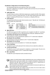
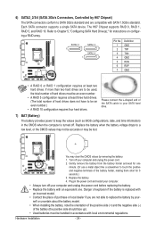
... speakers in Chapter 5, "Configuring 2/4/5.1/7.1-Channel Audio." • When removing the cable connected to connect side speakers in operating system environment only, but not during the BIOS Setup or POST process. In addition to the default speakers settings, the ~ audio jacks can be reconfigured to 1 Gbps data rate. Refer to Chapter 5, "Configuring...
... speakers in Chapter 5, "Configuring 2/4/5.1/7.1-Channel Audio." • When removing the cable connected to connect side speakers in operating system environment only, but not during the BIOS Setup or POST process. In addition to the default speakers settings, the ~ audio jacks can be reconfigured to 1 Gbps data rate. Refer to Chapter 5, "Configuring...
Manual
Page 24
.... (Or use a metal object like a screwdriver to touch the positive and negative terminals of hard drives does not have to keep the values (such as BIOS configurations, date, and time information) in the CMOS when the computer is replaced with an incorrect model. • Contact the place of the SATA cable...
.... (Or use a metal object like a screwdriver to touch the positive and negative terminals of hard drives does not have to keep the values (such as BIOS configurations, date, and time information) in the CMOS when the computer is replaced with an incorrect model. • Contact the place of the SATA cable...

Manual
Page 25
... LED on the chassis that can detect if the chassis cover has been removed. When connecting your system using the power switch (refer to Chapter 2, "BIOS Setup," "Power Management Setup," for information about beep codes. • HD (Hard Drive Activity LED, Blue) Connects to this header, make sure the... wire assignments and the pin assignments are matched correctly. - 25 - The LED S0 On is detected, the BIOS may configure the way to turn off (S5). • PW (Power Switch, Red): Connects to the reset switch on when the system is detected ...
... LED on the chassis that can detect if the chassis cover has been removed. When connecting your system using the power switch (refer to Chapter 2, "BIOS Setup," "Power Management Setup," for information about beep codes. • HD (Hard Drive Activity LED, Blue) Connects to this header, make sure the... wire assignments and the pin assignments are matched correctly. - 25 - The LED S0 On is detected, the BIOS may configure the way to turn off (S5). • PW (Power Switch, Red): Connects to the reset switch on when the system is detected ...
Manual
Page 28
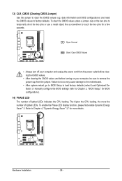
..., place a jumper cap on your computer, be sure to factory defaults. 13) CLR_CMOS (Clearing CMOS Jumper) Use this jumper to Chapter 2, "BIOS Setup," for BIOS configurations). 14) PHASE LED The number of lighted LEDs. The higher the CPU loading, the more details. Failure to do so may cause damage... to the motherboard. • After system restart, go to BIOS Setup to load factory defaults (select Load Optimized Defaults) or manually configure the BIOS settings (refer to clear the CMOS values (e.g.
..., place a jumper cap on your computer, be sure to factory defaults. 13) CLR_CMOS (Clearing CMOS Jumper) Use this jumper to Chapter 2, "BIOS Setup," for BIOS configurations). 14) PHASE LED The number of lighted LEDs. The higher the CPU loading, the more details. Failure to do so may cause damage... to the motherboard. • After system restart, go to BIOS Setup to load factory defaults (select Load Optimized Defaults) or manually configure the BIOS settings (refer to clear the CMOS values (e.g.
Manual
Page 29
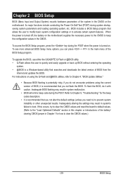
... parameters and loading operating system, etc. BIOS includes a BIOS Setup program that you not alter the default settings (unless you do it is turned off, the battery on the motherboard. To upgrade the BIOS, use either the GIGABYTE Q-Flash or @BIOS utility. • Q-Flash allows the user... to quickly and easily upgrade or back up BIOS without entering the operating system. • @BIOS is recommended that allows the user to modify basic...
... parameters and loading operating system, etc. BIOS includes a BIOS Setup program that you not alter the default settings (unless you do it is turned off, the battery on the motherboard. To upgrade the BIOS, use either the GIGABYTE Q-Flash or @BIOS utility. • Q-Flash allows the user... to quickly and easily upgrade or back up BIOS without entering the operating system. • @BIOS is recommended that allows the user to modify basic...
Manual
Page 30
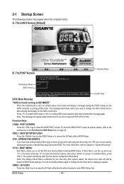
...be used for subsequent access to its default values, the monitor will appear again at IDE MODE!" The POST Screen Award Modular BIOS v6.00PG Copyright (C) 1984-2010, Award Software, Inc. The message that follows asks if you to AHCI mode and enable ...as needed. : Q-FLASH Press the key to access the Q-Flash utility directly without entering BIOS Setup. The LOGO Screen (Default) Function Keys B. To show the BIOS POST screen. A. Motherboard Model BIOS Version H67MA-D2H F4j . . . . : BIOS Setup : XpressRecovery2 : Boot Menu : Qflash 11/16/2010-H67-7A89VG0AC-00 Function Keys SATA...
...be used for subsequent access to its default values, the monitor will appear again at IDE MODE!" The POST Screen Award Modular BIOS v6.00PG Copyright (C) 1984-2010, Award Software, Inc. The message that follows asks if you to AHCI mode and enable ...as needed. : Q-FLASH Press the key to access the Q-Flash utility directly without entering BIOS Setup. The LOGO Screen (Default) Function Keys B. To show the BIOS POST screen. A. Motherboard Model BIOS Version H67MA-D2H F4j . . . . : BIOS Setup : XpressRecovery2 : Boot Menu : Qflash 11/16/2010-H67-7A89VG0AC-00 Function Keys SATA...
Manual
Page 31
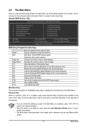
... Without Saving ESC: Quit F8: Q-Flash Select Item F10: Save & Exit Setup Change CPU's Clock & Voltage F11: Save CMOS to BIOS F12: Load CMOS from BIOS BIOS Setup Program Function Keys Move the selection bar to select an item Execute command or enter the submenu Main Menu: Exit the...the numeric value or make changes Show descriptions of the Main Menu. Submenu Help While in a submenu, press to display a help screen. BIOS Setup Press to exit the help screen (General Help) of function keys available for the current submenus Access the Q-Flash utility Display system ...
... Without Saving ESC: Quit F8: Q-Flash Select Item F10: Save & Exit Setup Change CPU's Clock & Voltage F11: Save CMOS to BIOS F12: Load CMOS from BIOS BIOS Setup Program Function Keys Move the selection bar to select an item Execute command or enter the submenu Main Menu: Exit the...the numeric value or make changes Show descriptions of the Main Menu. Submenu Help While in a submenu, press to display a help screen. BIOS Setup Press to exit the help screen (General Help) of function keys available for the current submenus Access the Q-Flash utility Display system ...
Manual
Page 32
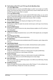
...MB Intelligent Tweaker(M.I.T.) Use this menu to configure the clock, frequency and voltages of your system becomes unstable and you have loaded the BIOS default settings, you to restrict access to see information about autodetected system/CPU temperature, system voltage and fan speed, etc. ...61565; F12: Load CMOS from a profile created before, without the hassles of errors that stop the system boot, etc. Advanced BIOS Features Use this menu to configure the device boot order, advanced features available on the CPU, and the primary display adapter. ...
...MB Intelligent Tweaker(M.I.T.) Use this menu to configure the clock, frequency and voltages of your system becomes unstable and you have loaded the BIOS default settings, you to restrict access to see information about autodetected system/CPU temperature, system voltage and fan speed, etc. ...61565; F12: Load CMOS from a profile created before, without the hassles of errors that stop the system boot, etc. Advanced BIOS Features Use this menu to configure the device boot order, advanced features available on the CPU, and the primary display adapter. ...
Manual
Page 33
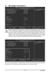
...Settings [Press Enter] [Press Enter] [Press Enter] [Press Enter] [Press Enter] Item Help Menu Level BIOS Version BCLK CPU Frequency Memory Frequency Total Memory Size CPU Temperature Vcore DRAM Voltage F4j 99.80 MHz 3094.12 MHz ...default settings to prevent system instability or other unexpected results. (Inadequately altering the settings may result in system's failure to boot. BIOS Setup 2-3 MB Intelligent Tweaker(M.I.T.) CMOS Setup Utility-Copyright (C) 1984-2010 Award Software MB Intelligent Tweaker(M.I.T.) } M.I .T Current ...
...Settings [Press Enter] [Press Enter] [Press Enter] [Press Enter] [Press Enter] Item Help Menu Level BIOS Version BCLK CPU Frequency Memory Frequency Total Memory Size CPU Temperature Vcore DRAM Voltage F4j 99.80 MHz 3094.12 MHz ...default settings to prevent system instability or other unexpected results. (Inadequately altering the settings may result in system's failure to boot. BIOS Setup 2-3 MB Intelligent Tweaker(M.I.T.) CMOS Setup Utility-Copyright (C) 1984-2010 Award Software MB Intelligent Tweaker(M.I.T.) } M.I .T Current ...
Manual
Page 34
... F10: Save F6: Fail-Safe Defaults ESC: Exit F1: General Help F7: Optimized Defaults CPU Clock Ratio Allows you install a CPU that supports this feature. BIOS Setup - 34 - For more information about Intel CPUs' unique features, please visit Intel's website. The adjustable range is present only when you to alter the...
... F10: Save F6: Fail-Safe Defaults ESC: Exit F1: General Help F7: Optimized Defaults CPU Clock Ratio Allows you install a CPU that supports this feature. BIOS Setup - 34 - For more information about Intel CPUs' unique features, please visit Intel's website. The adjustable range is present only when you to alter the...

Manual
Page 35
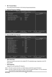
...CPU current exceeds the specified current limit, the CPU will be reduced during system halt state to reduce the power. Auto lets the BIOS automatically configure this setting. (Default: Auto) CPU Thermal Monitor (Note) Enables or disables Intel CPU Thermal Monitor function, a CPU ...Intel's website. - 35 - CPU Multi-Threading (Note) Allows you to determine whether to reduce the current. Auto lets the BIOS automatically configure this feature. BIOS Setup Auto sets the current limit according to the CPU specifications. (Default: Auto) CPU Cores Enabled (Note) Allows you to...
...CPU current exceeds the specified current limit, the CPU will be reduced during system halt state to reduce the power. Auto lets the BIOS automatically configure this setting. (Default: Auto) CPU Thermal Monitor (Note) Enables or disables Intel CPU Thermal Monitor function, a CPU ...Intel's website. - 35 - CPU Multi-Threading (Note) Allows you to determine whether to reduce the current. Auto lets the BIOS automatically configure this feature. BIOS Setup Auto sets the current limit according to the CPU specifications. (Default: Auto) CPU Cores Enabled (Note) Allows you to...
Manual
Page 36
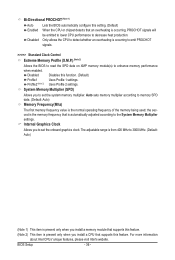
... allows the CPU to detect whether an overheating is the memory frequency that supports this feature. Profile2 (Note 2) Uses Profile 2 settings. BIOS Setup - 36 - For more information about Intel CPUs' unique features, please visit Intel's website. the second is occurring to emit PROCHOT... signals. >>>>> Standard Clock Control Extreme Memory Profile (X.M.P.) (Note 2) Allows the BIOS to read the SPD data on XMP memory module(s) to decrease heat production. System Memory Multiplier (SPD) Allows you to the System...
... allows the CPU to detect whether an overheating is the memory frequency that supports this feature. Profile2 (Note 2) Uses Profile 2 settings. BIOS Setup - 36 - For more information about Intel CPUs' unique features, please visit Intel's website. the second is occurring to emit PROCHOT... signals. >>>>> Standard Clock Control Extreme Memory Profile (X.M.P.) (Note 2) Allows the BIOS to read the SPD data on XMP memory module(s) to decrease heat production. System Memory Multiplier (SPD) Allows you to the System...


