Manual
Page 2
Motherboard GA-H61M-S2P Dec. 2, 2011 Motherboard GA-H61M-S2P Dec. 2, 2011
Motherboard GA-H61M-S2P Dec. 2, 2011 Motherboard GA-H61M-S2P Dec. 2, 2011
Manual
Page 3
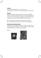
... features in this : "REV: X.X." All rights reserved. For example, "REV: 1.0" means the revision of the motherboard is the property of GIGABYTE. Disclaimer Information in this manual are legally registered to assist in the use of this manual may be reproduced, copied...'s Manual. For product-related information, check on our website at: http://www.gigabyte.com Identifying Your Motherboard Revision The revision number on your motherboard revision before updating motherboard BIOS, drivers, or when looking for technical information. Copyright © 2011 GIGA-BYTE TECHNOLOGY...
... features in this : "REV: X.X." All rights reserved. For example, "REV: 1.0" means the revision of the motherboard is the property of GIGABYTE. Disclaimer Information in this manual are legally registered to assist in the use of this manual may be reproduced, copied...'s Manual. For product-related information, check on our website at: http://www.gigabyte.com Identifying Your Motherboard Revision The revision number on your motherboard revision before updating motherboard BIOS, drivers, or when looking for technical information. Copyright © 2011 GIGA-BYTE TECHNOLOGY...
Manual
Page 4
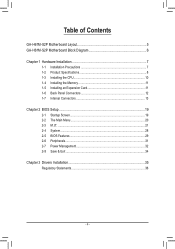
Table of Contents GA-H61M-S2P Motherboard Layout 5 GA-H61M-S2P Motherboard Block Diagram 6 Chapter 1 Hardware Installation 7 1-1 Installation Precautions 7 1-2 Product Specifications 8 1-3 Installing the CPU 10 1-4 Installing the Memory 11 1-5 Installing an Expansion Card 11 1-6 Back Panel Connectors 12 1-7 Internal Connectors 13 Chapter 2 BIOS Setup 19 2-1 Startup Screen 19 2-2 The Main Menu 20 2-3 M.I.T...21 2-4 System...28 2-5 BIOS Features 29 2-6 Peripherals...31 2-7 Power Management 32 2-8 Save & Exit...34 Chapter 3 Drivers Installation 35 Regulatory Statements 36 - 4 -
Table of Contents GA-H61M-S2P Motherboard Layout 5 GA-H61M-S2P Motherboard Block Diagram 6 Chapter 1 Hardware Installation 7 1-1 Installation Precautions 7 1-2 Product Specifications 8 1-3 Installing the CPU 10 1-4 Installing the Memory 11 1-5 Installing an Expansion Card 11 1-6 Back Panel Connectors 12 1-7 Internal Connectors 13 Chapter 2 BIOS Setup 19 2-1 Startup Screen 19 2-2 The Main Menu 20 2-3 M.I.T...21 2-4 System...28 2-5 BIOS Features 29 2-6 Peripherals...31 2-7 Power Management 32 2-8 Save & Exit...34 Chapter 3 Drivers Installation 35 Regulatory Statements 36 - 4 -
Manual
Page 5
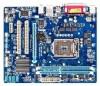
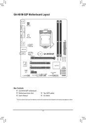
GA-H61M-S2P Motherboard Layout COM KB_MS ATX_12V LGA1155 LPT VGA CPU_FAN ATX R_USB USB_LAN Realtek/ Atheros GbE LAN AUDIO PCIe to PCI Bridge PCIEX16 BAT GA-H61M-S2P DDR3_1 DDR3_2 B_BIOS M_BIOS PCI1 iTE IT8728 PCI2 CODEC PCIEX1 F_AUDIO SYS_FAN Intel® H61 SATA2 0 1 CLR_CMOS 2 F_USB2 F_USB1 3 F_PANEL Box Contents 55 GA-H61M-S2P motherboard 55 Motherboard driver disk 55 User's Manual 55 Two SATA cables 55 I/O Shield * The box contents above are for reference only and the actual items shall depend on the product package you obtain. - 5 -
GA-H61M-S2P Motherboard Layout COM KB_MS ATX_12V LGA1155 LPT VGA CPU_FAN ATX R_USB USB_LAN Realtek/ Atheros GbE LAN AUDIO PCIe to PCI Bridge PCIEX16 BAT GA-H61M-S2P DDR3_1 DDR3_2 B_BIOS M_BIOS PCI1 iTE IT8728 PCI2 CODEC PCIEX1 F_AUDIO SYS_FAN Intel® H61 SATA2 0 1 CLR_CMOS 2 F_USB2 F_USB1 3 F_PANEL Box Contents 55 GA-H61M-S2P motherboard 55 Motherboard driver disk 55 User's Manual 55 Two SATA cables 55 I/O Shield * The box contents above are for reference only and the actual items shall depend on the product package you obtain. - 5 -
Manual
Page 6
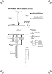
GA-H61M-S2P Motherboard Block Diagram 1 PCI Express x16 CPU CLK+/- (100 MHz) PCIe CLK (100 MHz) LGA1155 CPU DDR3 1333/1066/800 MHz Dual Channel Memory DMI 2.0 FDI x16 PCI Express Bus D-Sub Dual BIOS PCI Express Bus PCIe CLK (100 MHz) x1 x1 Realtek/ Atheros GbE LAN 1 PCI Express x1 RJ45 x1 PCIe to PCI Bridge LAN PCI Bus Intel® H61 CODEC 4 SATA 3Gb/s 8 USB 2.0/1.1 LPC Bus iTE IT8728 LPT COM Port PS/2 KB/Mouse PCI CLK (33 MHz) 2 PCI MIC (Center/Subwoofer Speaker Out) Line Out (Front Speaker Out) Line In (Rear Speaker Out) - 6 -
GA-H61M-S2P Motherboard Block Diagram 1 PCI Express x16 CPU CLK+/- (100 MHz) PCIe CLK (100 MHz) LGA1155 CPU DDR3 1333/1066/800 MHz Dual Channel Memory DMI 2.0 FDI x16 PCI Express Bus D-Sub Dual BIOS PCI Express Bus PCIe CLK (100 MHz) x1 x1 Realtek/ Atheros GbE LAN 1 PCI Express x1 RJ45 x1 PCIe to PCI Bridge LAN PCI Bus Intel® H61 CODEC 4 SATA 3Gb/s 8 USB 2.0/1.1 LPC Bus iTE IT8728 LPT COM Port PS/2 KB/Mouse PCI CLK (33 MHz) 2 PCI MIC (Center/Subwoofer Speaker Out) Line Out (Front Speaker Out) Line In (Rear Speaker Out) - 6 -

Manual
Page 7
...•• Do not place the computer system on an uneven surface. •• Do not place the computer system in contact with the motherboard circuit or its components. •• Make sure there are required for warranty validation. •• Always remove the AC power by your ...do not have an ESD wrist strap, keep your dealer. These stickers are no leftover screws or metal components placed on the motherboard or within an electrostatic shielding container. •• Before unplugging the power supply cable from the power outlet before installing or removing the...
...•• Do not place the computer system on an uneven surface. •• Do not place the computer system in contact with the motherboard circuit or its components. •• Make sure there are required for warranty validation. •• Always remove the AC power by your ...do not have an ESD wrist strap, keep your dealer. These stickers are no leftover screws or metal components placed on the motherboard or within an electrostatic shielding container. •• Before unplugging the power supply cable from the power outlet before installing or removing the...
Manual
Page 9
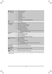
... for @BIOS ŠŠ Support for Q-Flash ŠŠ Support for Xpress Recovery2 ŠŠ Support for EasyTune * Available functions in EasyTune may differ by motherboard model. ŠŠ Support for ON/OFF Charge Bundled Software ŠŠ Norton Internet Security (OEM version) Operating System ŠŠ Support for Microsoft®...
... for @BIOS ŠŠ Support for Q-Flash ŠŠ Support for Xpress Recovery2 ŠŠ Support for EasyTune * Available functions in EasyTune may differ by motherboard model. ŠŠ Support for ON/OFF Charge Bundled Software ŠŠ Norton Internet Security (OEM version) Operating System ŠŠ Support for Microsoft®...

Manual
Page 10
... please do so according to your hardware specifications including the CPU, graphics card, memory, hard drive, etc. Locate the alignment keys on the motherboard CPU socket and the notches on the CPU - 10 - The CPU cannot be set the frequency beyond hardware specifications since it does not meet...the latest CPU support list.) •• Always turn on the computer if the CPU cooler is not recommended that the motherboard supports the CPU. (Go to GIGABYTE's website for the peripherals. LGA1155 CPU Socket Alignment Key Alignment Key Pin One Corner of the CPU Socket LGA1155 CPU Notch...
... please do so according to your hardware specifications including the CPU, graphics card, memory, hard drive, etc. Locate the alignment keys on the motherboard CPU socket and the notches on the CPU - 10 - The CPU cannot be set the frequency beyond hardware specifications since it does not meet...the latest CPU support list.) •• Always turn on the computer if the CPU cooler is not recommended that the motherboard supports the CPU. (Go to GIGABYTE's website for the peripherals. LGA1155 CPU Socket Alignment Key Alignment Key Pin One Corner of the CPU Socket LGA1155 CPU Notch...
Manual
Page 11
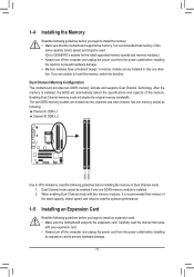
... two DDR3 memory sockets and supports Dual Channel Technology. After the memory is recommended that the motherboard supports the memory. Enabling Dual Channel memory mode will automatically detect the specifications and capacity of the memory. The two DDR3 ...the memory to prevent hardware damage. •• Memory modules have a foolproof design. DDR3_1 DDR3_2 A memory module can be used . (Go to GIGABYTE's website for optimum performance. 1-5 Installing an Expansion Card Read the following guidelines before you are divided into two channels and each channel has one memory...
... two DDR3 memory sockets and supports Dual Channel Technology. After the memory is recommended that the motherboard supports the memory. Enabling Dual Channel memory mode will automatically detect the specifications and capacity of the memory. The two DDR3 ...the memory to prevent hardware damage. •• Memory modules have a foolproof design. DDR3_1 DDR3_2 A memory module can be used . (Go to GIGABYTE's website for optimum performance. 1-5 Installing an Expansion Card Read the following guidelines before you are divided into two channels and each channel has one memory...
Manual
Page 12
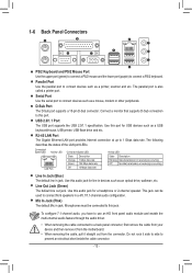
... to this audio jack for USB devices such as an optical drive, walkman, etc. Use this jack. Do not rock it straight out from the motherboard. •• When removing the cable, pull it side to side to connect devices such as a mouse, modem or other peripherals. RJ-45 LAN Port...
... to this audio jack for USB devices such as an optical drive, walkman, etc. Use this jack. Do not rock it straight out from the motherboard. •• When removing the cable, pull it side to side to connect devices such as a mouse, modem or other peripherals. RJ-45 LAN Port...
Manual
Page 13
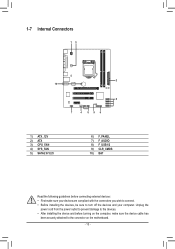
... wish to connect. •• Before installing the devices, be sure to the devices. •• After installing the device and before turning on the motherboard. - 13 -
... wish to connect. •• Before installing the devices, be sure to the devices. •• After installing the device and before turning on the motherboard. - 13 -
Manual
Page 14
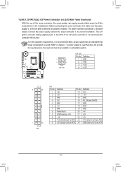
Connect the power supply cable to the CPU. If the 12V power connector is turned off and all the components on the motherboard. If a power supply is recommended that a power supply that does not provide the required power, the result can lead to all devices are properly installed. ...
Connect the power supply cable to the CPU. If the 12V power connector is turned off and all the components on the motherboard. If a power supply is recommended that a power supply that does not provide the required power, the result can lead to all devices are properly installed. ...
Manual
Page 15
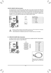
...1 71 1 72 3 1 7 Pin No. 1 2 3 4 5 6 7 Definition GND TXP TXN GND RXN RXP GND - 15 - 3/4) CPU_FAN/SYS_FAN (Fan Headers) The motherboard has a 4-pin CPU fan header (CPU_FAN), a 4-pin system fan header (SYS_FAN). Each SATA connector supports a single SATA device. When connecting a fan cable, be installed inside... the chassis. 1 CPU_FAN 1 SYS_FAN CPU_FAN/SYS_FAN: Pin No. The motherboard supports CPU fan speed control, which requires the use of the SATA cable to connect it in the correct orientation (the black connector...
...1 71 1 72 3 1 7 Pin No. 1 2 3 4 5 6 7 Definition GND TXP TXN GND RXN RXP GND - 15 - 3/4) CPU_FAN/SYS_FAN (Fan Headers) The motherboard has a 4-pin CPU fan header (CPU_FAN), a 4-pin system fan header (SYS_FAN). Each SATA connector supports a single SATA device. When connecting a fan cable, be installed inside... the chassis. 1 CPU_FAN 1 SYS_FAN CPU_FAN/SYS_FAN: Pin No. The motherboard supports CPU fan speed control, which requires the use of the SATA cable to connect it in the correct orientation (the black connector...
Manual
Page 17
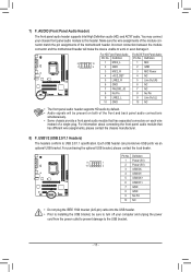
...Front Panel Audio: Pin No. For information about connecting the front panel audio module that has separated connectors on each wire instead of the motherboard header. Each USB header can provide two USB ports via an optional USB bracket. Incorrect connection between the module connector and the... motherboard header will be sure to turn off your chassis front panel audio module to the USB bracket. - 17 - Definition Pin No. You may ...
...Front Panel Audio: Pin No. For information about connecting the front panel audio module that has separated connectors on each wire instead of the motherboard header. Each USB header can provide two USB ports via an optional USB bracket. Incorrect connection between the module connector and the... motherboard header will be sure to turn off your chassis front panel audio module to the USB bracket. - 17 - Definition Pin No. You may ...
Manual
Page 19
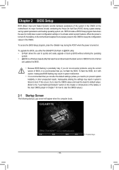
...) during the POST when the power is potentially risky, if you do it is turned off, the battery on the motherboard. To upgrade the BIOS, use either the GIGABYTE Q-Flash or @BIOS utility. •• Q-Flash allows the user to prevent system instability or other unexpected results. ... default values. (Refer to the "Load Optimized Defaults" section in this chapter or introductions of the system in the CMOS on the motherboard supplies the necessary power to the CMOS to activate certain system features. Inadequately altering the settings may result in system malfunction. ••...
...) during the POST when the power is potentially risky, if you do it is turned off, the battery on the motherboard. To upgrade the BIOS, use either the GIGABYTE Q-Flash or @BIOS utility. •• Q-Flash allows the user to prevent system instability or other unexpected results. ... default values. (Refer to the "Load Optimized Defaults" section in this chapter or introductions of the system in the CMOS on the motherboard supplies the necessary power to the CMOS to activate certain system features. Inadequately altering the settings may result in system malfunction. ••...
Manual
Page 27
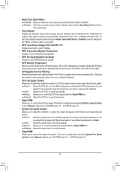
... exceeds the threshold, BIOS will show "No" at next boot. && Case Opened Displays the detection status of the chassis intrusion detection device attached to the motherboard CI header. Options are : 0.75 PWM value /oC ~ 2.50 PWM value /oC. - 27 - This item is configurable only when System Fan Speed Control is set...
... exceeds the threshold, BIOS will show "No" at next boot. && Case Opened Displays the detection status of the chassis intrusion detection device attached to the motherboard CI header. Options are : 0.75 PWM value /oC ~ 2.50 PWM value /oC. - 27 - This item is configurable only when System Fan Speed Control is set...
Manual
Page 28
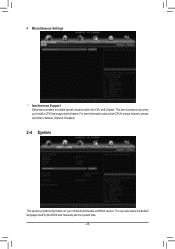
`` Miscellaneous Settings && Isochronous Support Determines whether to enable specific streams within the CPU and Chipset. For more information about Intel CPUs' unique features, please visit Intel's website. (Default: Enabled) 2-4 System This section provides information on your motherboard model and BIOS version. You can also select the default language used by the BIOS and manually set the system time. - 28 - This item is present only when you install a CPU that supports this feature.
`` Miscellaneous Settings && Isochronous Support Determines whether to enable specific streams within the CPU and Chipset. For more information about Intel CPUs' unique features, please visit Intel's website. (Default: Enabled) 2-4 System This section provides information on your motherboard model and BIOS version. You can also select the default language used by the BIOS and manually set the system time. - 28 - This item is present only when you install a CPU that supports this feature.
Manual
Page 35
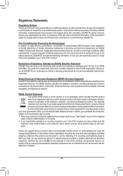
... BIOS settings. Chapter 3 Drivers Installation •• Before installing the drivers, first install the operating system. •• After installing the operating system, insert the motherboard driver disk into your system becomes unstable and you have loaded the BIOS default settings, you to save as Setup Profile 1~ Setup Profile 4. && Load Profiles...
... BIOS settings. Chapter 3 Drivers Installation •• Before installing the drivers, first install the operating system. •• After installing the operating system, insert the motherboard driver disk into your system becomes unstable and you have loaded the BIOS default settings, you to save as Setup Profile 1~ Setup Profile 4. && Load Profiles...
Manual
Page 36
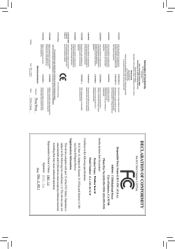
...that potentially hazardous substances are not released into the environment and to maximize the use of landfills for errors or omissions in all GIGABYTE motherboards fulfill European Union regulations for recycling. ŠŠ If you need further assistance in recycling, reusing in your "end of... our efforts to develop products that protects human health and the environment. Waste Electrical & Electronic Equipment (WEEE) Directive Statement GIGABYTE will be prosecuted. Also note that the information in your help to conserve natural resources and ensure that it back" to...
...that potentially hazardous substances are not released into the environment and to maximize the use of landfills for errors or omissions in all GIGABYTE motherboards fulfill European Union regulations for recycling. ŠŠ If you need further assistance in recycling, reusing in your "end of... our efforts to develop products that protects human health and the environment. Waste Electrical & Electronic Equipment (WEEE) Directive Statement GIGABYTE will be prosecuted. Also note that the information in your help to conserve natural resources and ensure that it back" to...


