Manual
Page 1
GA-H55M-D2H LGA1156 socket motherboard for Intel® Core™ i7 processor family/ Intel® Core™ i5 processor family/ Intel® Core™ i3 processor family User's Manual Rev. 1301 12ME-H55MD2H-1301R
GA-H55M-D2H LGA1156 socket motherboard for Intel® Core™ i7 processor family/ Intel® Core™ i5 processor family/ Intel® Core™ i3 processor family User's Manual Rev. 1301 12ME-H55MD2H-1301R
Manual
Page 2
Motherboard GA-H55M-D2H May 17, 2010 Motherboard GA-H55M-D2H May 17, 2010
Motherboard GA-H55M-D2H May 17, 2010 Motherboard GA-H55M-D2H May 17, 2010
Manual
Page 3
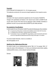
... in this manual is protected by copyright laws and is 1.0. Disclaimer Information in the use GIGABYTE's unique features, read the User's Manual. For example, "REV: 1.0" means the revision of the motherboard is the property of this manual may be reproduced, copied, translated, transmitted, or published ...or when looking for technical information. For product-related information, check on our website at: http://www.gigabyte.com.tw Identifying Your Motherboard Revision The revision number on our website. Documentation Classifications In order to use of this manual are legally ...
... in this manual is protected by copyright laws and is 1.0. Disclaimer Information in the use GIGABYTE's unique features, read the User's Manual. For example, "REV: 1.0" means the revision of the motherboard is the property of this manual may be reproduced, copied, translated, transmitted, or published ...or when looking for technical information. For product-related information, check on our website at: http://www.gigabyte.com.tw Identifying Your Motherboard Revision The revision number on our website. Documentation Classifications In order to use of this manual are legally ...

Manual
Page 4
Table of Contents Box Contents...6 Optional Items...6 GA-H55M-D2H Motherboard Layout 7 GA-H55M-D2H Motherboard Block Diagram 8 Chapter 1 Hardware Installation 9 1-1 Installation Precautions 9 1-2 Product Specifications 10 1-3 Installing the CPU and CPU Cooler 13 1-3-1 Installing the CPU 13 1-3-2 Installing the CPU Cooler ...
Table of Contents Box Contents...6 Optional Items...6 GA-H55M-D2H Motherboard Layout 7 GA-H55M-D2H Motherboard Block Diagram 8 Chapter 1 Hardware Installation 9 1-1 Installation Precautions 9 1-2 Product Specifications 10 1-3 Installing the CPU and CPU Cooler 13 1-3-1 Installing the CPU 13 1-3-2 Installing the CPU Cooler ...
Manual
Page 6
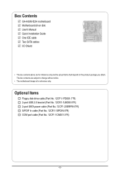
Box Contents GA-H55M-D2H motherboard Motherboard driver disk User's Manual Quick Installation Guide One IDE cable Two SATA cables I/O Shield • The box contents above are subject to change without notice. • The motherboard image is for reference only and the actual items shall depend on the product package you obtain. The box contents are for...
Box Contents GA-H55M-D2H motherboard Motherboard driver disk User's Manual Quick Installation Guide One IDE cable Two SATA cables I/O Shield • The box contents above are subject to change without notice. • The motherboard image is for reference only and the actual items shall depend on the product package you obtain. The box contents are for...
Manual
Page 7
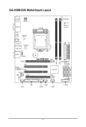
GA-H55M-D2H Motherboard Layout KB_USB ATX_12V VGA_DVI LGA1156 PHASE LED iTE IT8720 HDMI SYS_FAN OPTICAL R_USB USB_LAN CPU_FAN AUDIO F_AUDIO PCIEX16 PCI1 Realtek RTL8111D/8111E PCI2 SPDIF_O SPDIF_I CODEC PCIEX4 IDE ATX BAT GA-H55M-D2H Intel® H55 JMicron JMB368 M_BIOS B_BIOS CLR_CMOS FDD CD_IN F_USB2 COMA F_USB1 F_PANEL DDR3_1 DDR3_2 SATA2_5 SATA2_2 SATA2_4 SATA2_1 SATA2_3 SATA2_0 - 7 -
GA-H55M-D2H Motherboard Layout KB_USB ATX_12V VGA_DVI LGA1156 PHASE LED iTE IT8720 HDMI SYS_FAN OPTICAL R_USB USB_LAN CPU_FAN AUDIO F_AUDIO PCIEX16 PCI1 Realtek RTL8111D/8111E PCI2 SPDIF_O SPDIF_I CODEC PCIEX4 IDE ATX BAT GA-H55M-D2H Intel® H55 JMicron JMB368 M_BIOS B_BIOS CLR_CMOS FDD CD_IN F_USB2 COMA F_USB1 F_PANEL DDR3_1 DDR3_2 SATA2_5 SATA2_2 SATA2_4 SATA2_1 SATA2_3 SATA2_0 - 7 -
Manual
Page 8
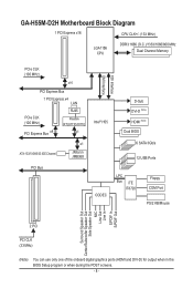
GA-H55M-D2H Motherboard Block Diagram 1 PCI Express x16 CPU CLK+/- (133 MHz) LGA1156 CPU DDR3 1666 (O.C.)/1333/1066/800 MHz Dual Channel Memory PCIe CLK (100 MHz) x16 ...
GA-H55M-D2H Motherboard Block Diagram 1 PCI Express x16 CPU CLK+/- (133 MHz) LGA1156 CPU DDR3 1666 (O.C.)/1333/1066/800 MHz Dual Channel Memory PCIe CLK (100 MHz) x16 ...

Manual
Page 9
...validation. • Always remove the AC power by your dealer. If you are connected tightly and securely. • When handling the motherboard, avoid touching any installation steps or have it on top of an antistatic pad or within an electrostatic shielding container. • Before...cables and power connectors of your hands dry and first touch a metal object to eliminate static electricity. • Prior to installing the motherboard, please have a problem related to wear an electrostatic discharge (ESD) wrist strap when handling electronic com- Prior to installation, carefully read ...
...validation. • Always remove the AC power by your dealer. If you are connected tightly and securely. • When handling the motherboard, avoid touching any installation steps or have it on top of an antistatic pad or within an electrostatic shielding container. • Before...cables and power connectors of your hands dry and first touch a metal object to eliminate static electricity. • Prior to installing the motherboard, please have a problem related to wear an electrostatic discharge (ESD) wrist strap when handling electronic com- Prior to installation, carefully read ...
Manual
Page 12
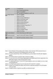
... CPU/system fan speed control function is supported will depend on the CPU/system cooler you install. (Note 8) Available functions in EasyTune may differ by motherboard model.
... CPU/system fan speed control function is supported will depend on the CPU/system cooler you install. (Note 8) Available functions in EasyTune may differ by motherboard model.
Manual
Page 13
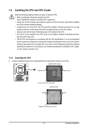
... and unplug the power cord from the power outlet before you begin to install the CPU: • Make sure that the motherboard supports the CPU. (Go to GIGABYTE's website for the latest CPU support list.) • Always turn on the computer if the CPU cooler is not recommended that... to your hardware specifications including the CPU, graphics card, memory, hard drive, etc. 1-3-1 Installing the CPU A. Locate the alignment keys on the motherboard CPU socket and the notches on the CPU - 13 - LGA1156 CPU Socket Alignment Key Alignment Key Pin One Corner of the CPU Socket LGA1156 CPU...
... and unplug the power cord from the power outlet before you begin to install the CPU: • Make sure that the motherboard supports the CPU. (Go to GIGABYTE's website for the latest CPU support list.) • Always turn on the computer if the CPU cooler is not recommended that... to your hardware specifications including the CPU, graphics card, memory, hard drive, etc. 1-3-1 Installing the CPU A. Locate the alignment keys on the motherboard CPU socket and the notches on the CPU - 13 - LGA1156 CPU Socket Alignment Key Alignment Key Pin One Corner of the CPU Socket LGA1156 CPU...

Manual
Page 14
..., make sure the front end of the socket cover and use your thumb and index fingers. Step 5: Push the CPU socket lever back into the motherboard CPU socket. NOTE: Hold the CPU socket lever by the handle, not the lever base portion. Step 1: Gently press the CPU socket lever handle down...
..., make sure the front end of the socket cover and use your thumb and index fingers. Step 5: Push the CPU socket lever back into the motherboard CPU socket. NOTE: Hold the CPU socket lever by the handle, not the lever base portion. Step 1: Gently press the CPU socket lever handle down...

Manual
Page 15
...should hear a "click" when pushing down on installing the cooler.) Step 5: After the installation, check the back of thermal grease on the motherboard. Check that the Male and Female push pins are joined closely. (Refer to your CPU cooler installation manual for instructions on the push pins ...the CPU cooler may adhere to the CPU. 1-3-2 Installing the CPU Cooler Follow the steps below to correctly install the CPU cooler on the motherboard. (The following procedure uses Intel® boxed cooler as the picture above shows, the installation is to install.) Step 3: Place the ...
...should hear a "click" when pushing down on installing the cooler.) Step 5: After the installation, check the back of thermal grease on the motherboard. Check that the Male and Female push pins are joined closely. (Refer to your CPU cooler installation manual for instructions on the push pins ...the CPU cooler may adhere to the CPU. 1-3-2 Installing the CPU Cooler Follow the steps below to correctly install the CPU cooler on the motherboard. (The following procedure uses Intel® boxed cooler as the picture above shows, the installation is to install.) Step 3: Place the ...
Manual
Page 16
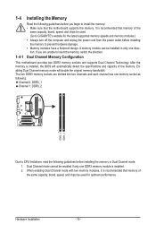
... DDR3 memory module is installed, the BIOS will double the original memory bandwidth. A memory module can be used . (Go to GIGABYTE's website for optimum performance. The two DDR3 memory sockets are unable to prevent hardware damage. • Memory modules have a foolproof ...design. Dual Channel Memory Configuration This motherboard provides two DDR3 memory sockets and supports Dual Channel Technology. After the memory is installed. 2. When enabling Dual Channel mode with ...
... DDR3 memory module is installed, the BIOS will double the original memory bandwidth. A memory module can be used . (Go to GIGABYTE's website for optimum performance. The two DDR3 memory sockets are unable to prevent hardware damage. • Memory modules have a foolproof ...design. Dual Channel Memory Configuration This motherboard provides two DDR3 memory sockets and supports Dual Channel Technology. After the memory is installed. 2. When enabling Dual Channel mode with ...

Manual
Page 17
... the memory module. Spread the retaining clips at both ends of the socket will snap into the memory socket. Place the memory module on this motherboard. Step 2: The clips at both ends of the memory socket. Step 1: Note the orientation of the memory, push down on the memory and insert it...
... the memory module. Spread the retaining clips at both ends of the socket will snap into the memory socket. Place the memory module on this motherboard. Step 2: The clips at both ends of the memory socket. Step 1: Note the orientation of the memory, push down on the memory and insert it...
Manual
Page 18
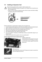
... install your expansion card(s). 7. Remove the metal slot cover from the power outlet before you begin to install an expansion card: • Make sure the motherboard supports the expansion card. Secure the card's metal bracket to the chassis back panel with the expansion card in the expansion slot. 1. After installing all...
... install your expansion card(s). 7. Remove the metal slot cover from the power outlet before you begin to install an expansion card: • Make sure the motherboard supports the expansion card. Secure the card's metal bracket to the chassis back panel with the expansion card in the expansion slot. 1. After installing all...
Manual
Page 20
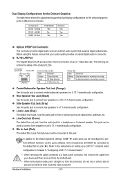
...) The default Mic in jack ( ). Only microphones still MUST be connected to an external audio system that your device and then remove it from the motherboard. • When removing the cable, pull it side to side to perform different functions via the audio software. Side Speaker Out Jack (Gray) Use this...
...) The default Mic in jack ( ). Only microphones still MUST be connected to an external audio system that your device and then remove it from the motherboard. • When removing the cable, pull it side to side to perform different functions via the audio software. Side Speaker Out Jack (Gray) Use this...

Manual
Page 21
...) F_AUDIO 11) CD_IN 12) SPDIF_I 13) SPDIF_O 14) F_USB1/F_USB2 15) COMA 16) CLR_CMOS 17) PHASE LED Read the following guidelines before turning on the motherboard. - 21 - Hardware Installation
...) F_AUDIO 11) CD_IN 12) SPDIF_I 13) SPDIF_O 14) F_USB1/F_USB2 15) COMA 16) CLR_CMOS 17) PHASE LED Read the following guidelines before turning on the motherboard. - 21 - Hardware Installation

Manual
Page 22
... is used (500W or greater). Connect the power supply cable to the CPU. If a power supply is turned off and all the components on the motherboard. The 12V power connector mainly supplies power to the power connector in the correct orientation. To meet expansion requirements, it is not connected, the computer...
... is used (500W or greater). Connect the power supply cable to the CPU. If a power supply is turned off and all the components on the motherboard. The 12V power connector mainly supplies power to the power connector in the correct orientation. To meet expansion requirements, it is not connected, the computer...
Manual
Page 23
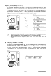
Most fan headers possess a foolproof insertion design. The motherboard supports CPU fan speed control, which requires the use of different color. Definition 1 GND 2 +12V / Speed Control 3 Sense 4 Speed Control SYS_FAN: Pin No. Overheating may ... floppy disk drives supported are not configuration jumper blocks. The types of the connector and the floppy disk drive cable. 3/4) CPU_FAN/SYS_FAN (Fan Headers) The motherboard has a 4-pin CPU fan header (CPU_FAN) and a 4-pin system fan header (SYS_FAN). For optimum heat dissipation, it in damage to the CPU or the system...
Most fan headers possess a foolproof insertion design. The motherboard supports CPU fan speed control, which requires the use of different color. Definition 1 GND 2 +12V / Speed Control 3 Sense 4 Speed Control SYS_FAN: Pin No. Overheating may ... floppy disk drives supported are not configuration jumper blocks. The types of the connector and the floppy disk drive cable. 3/4) CPU_FAN/SYS_FAN (Fan Headers) The motherboard has a 4-pin CPU fan header (CPU_FAN) and a 4-pin system fan header (SYS_FAN). For optimum heat dissipation, it in damage to the CPU or the system...
Manual
Page 27
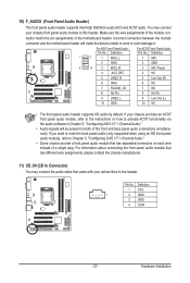
... HD front panel audio module), refer to work or even damage it. Incorrect connection between the module connector and the motherboard header will be present on each wire instead of the motherboard header. For information about connecting the front panel audio module that came with your chassis front panel audio module to...
... HD front panel audio module), refer to work or even damage it. Incorrect connection between the module connector and the motherboard header will be present on each wire instead of the motherboard header. For information about connecting the front panel audio module that came with your chassis front panel audio module to...


