Manual
Page 1
GA-G41MT-S2 LGA775 socket motherboard for Intel® Core™ processor family/ Intel® Pentium® processor family/Intel® Celeron® processor family User's Manual Rev. 1301 12ME-G41MTS2-1301R
GA-G41MT-S2 LGA775 socket motherboard for Intel® Core™ processor family/ Intel® Pentium® processor family/Intel® Celeron® processor family User's Manual Rev. 1301 12ME-G41MTS2-1301R
Manual
Page 2
Motherboard GA-G41MT-S2 Oct. 1, 2010 Motherboard GA-G41MT-S2 Oct. 1, 2010
Motherboard GA-G41MT-S2 Oct. 1, 2010 Motherboard GA-G41MT-S2 Oct. 1, 2010
Manual
Page 3
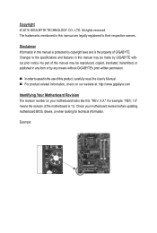
...part of this manual may be reproduced, copied, translated, transmitted, or published in the use of GIGABYTE. For example, "REV: 1.0" means the revision of the motherboard is the property of this product, carefully read the User's Manual. For product-related ...information, check on our website at: http://www.gigabyte.com Identifying Your Motherboard Revision The revision number on your motherboard revision before updating motherboard BIOS, drivers, or when looking for technical information. Example: All rights reserved. Copyright...
...part of this manual may be reproduced, copied, translated, transmitted, or published in the use of GIGABYTE. For example, "REV: 1.0" means the revision of the motherboard is the property of this product, carefully read the User's Manual. For product-related ...information, check on our website at: http://www.gigabyte.com Identifying Your Motherboard Revision The revision number on your motherboard revision before updating motherboard BIOS, drivers, or when looking for technical information. Example: All rights reserved. Copyright...
Manual
Page 4
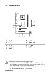
Table of Contents GA-G41MT-S2 Motherboard Layout 5 Chapter 1 Hardware Installation 6 1-1 Installation Precautions 6 1-2 Product Specifications 7 1-3 Installing the CPU and CPU Cooler 9 1-3-1 Installing the CPU...9 1-4 Installing the Memory 10 1-4-1 Dual Channel Memory Configuration ...
Table of Contents GA-G41MT-S2 Motherboard Layout 5 Chapter 1 Hardware Installation 6 1-1 Installation Precautions 6 1-2 Product Specifications 7 1-3 Installing the CPU and CPU Cooler 9 1-3-1 Installing the CPU...9 1-4 Installing the Memory 10 1-4-1 Dual Channel Memory Configuration ...
Manual
Page 5
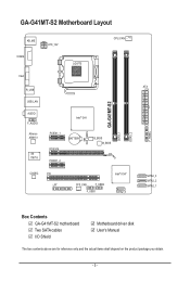
GA-G41MT-S2 Motherboard Layout KB_MS COMA ATX_12V VGA LGA775 CPU_FAN R_USB USB_LAN AUDIO F_AUDIO Atheros AR8151 iTE IT8718 Intel® G41 PCIEX1_1 PCIEX16 BATTERY PCIEX1_2 B_BIOS M_BIOS CODEC PCI LPT SYS_FAN F_USB2 F_USB1 Intel® ICH7 SATA2_0 CLR_CMOS GA-G41MT-S2 DDR3_1 DDR3_2 F_PANEL ATX SATA2_3 SATA2_2 SATA2_1 Box Contents GA-G41MT-S2 motherboard Two SATA cables I/O Shield Motherboard driver disk User's Manual The box contents above are for reference only and the actual items shall depend on the product package you obtain. - 5 -
GA-G41MT-S2 Motherboard Layout KB_MS COMA ATX_12V VGA LGA775 CPU_FAN R_USB USB_LAN AUDIO F_AUDIO Atheros AR8151 iTE IT8718 Intel® G41 PCIEX1_1 PCIEX16 BATTERY PCIEX1_2 B_BIOS M_BIOS CODEC PCI LPT SYS_FAN F_USB2 F_USB1 Intel® ICH7 SATA2_0 CLR_CMOS GA-G41MT-S2 DDR3_1 DDR3_2 F_PANEL ATX SATA2_3 SATA2_2 SATA2_1 Box Contents GA-G41MT-S2 motherboard Two SATA cables I/O Shield Motherboard driver disk User's Manual The box contents above are for reference only and the actual items shall depend on the product package you obtain. - 5 -
Manual
Page 6
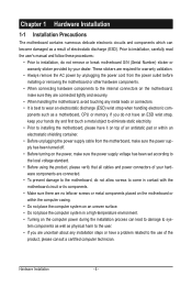
...are required for warranty validation. • Always remove the AC power by your dealer. Chapter 1 Hardware Installation 1-1 Installation Precautions The motherboard contains numerous delicate electronic circuits and components which can become damaged as a result of your hardware components are connected. • To ...to the internal connectors on the computer power during the installation process can lead to damage to system components as well as a motherboard, CPU or memory. Prior to installation, carefully read the user's manual and follow these procedures: • Prior to installation,...
...are required for warranty validation. • Always remove the AC power by your dealer. Chapter 1 Hardware Installation 1-1 Installation Precautions The motherboard contains numerous delicate electronic circuits and components which can become damaged as a result of your hardware components are connected. • To ...to the internal connectors on the computer power during the installation process can lead to damage to system components as well as a motherboard, CPU or memory. Prior to installation, carefully read the user's manual and follow these procedures: • Prior to installation,...
Manual
Page 8
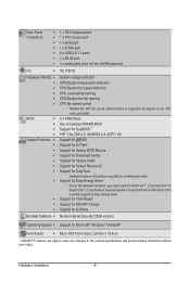
... Microsoft® Windows® 7/Vista/XP Form Factor w Micro ATX Form Factor; 24.4cm x 19.4cm * GIGABYTE reserves the right to make any changes to enable support for EasyTune * Available functions in EasyTune may differ by motherboard model. Back Panel Connectors w 1 x PS/2 keyboard port w 1 x PS/2 mouse port w 1 x serial port w 1 x D-Sub port w 4 x USB...
... Microsoft® Windows® 7/Vista/XP Form Factor w Micro ATX Form Factor; 24.4cm x 19.4cm * GIGABYTE reserves the right to make any changes to enable support for EasyTune * Available functions in EasyTune may differ by motherboard model. Back Panel Connectors w 1 x PS/2 keyboard port w 1 x PS/2 mouse port w 1 x serial port w 1 x D-Sub port w 4 x USB...
Manual
Page 9
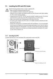
...your hardware specifications including the CPU, graphics card, memory, hard drive, etc. 1-3-1 Installing the CPU Locate the alignment keys on the motherboard CPU socket and the notches on the computer if the CPU cooler is not recommended that the system bus frequency be inserted if oriented... incorrectly. (Or you begin to install the CPU: • Make sure that the motherboard supports the CPU. (Go to GIGABYTE's website for the peripherals. Hardware Installation It is not installed, otherwise overheating and dam- The CPU cannot be set the ...
...your hardware specifications including the CPU, graphics card, memory, hard drive, etc. 1-3-1 Installing the CPU Locate the alignment keys on the motherboard CPU socket and the notches on the computer if the CPU cooler is not recommended that the system bus frequency be inserted if oriented... incorrectly. (Or you begin to install the CPU: • Make sure that the motherboard supports the CPU. (Go to GIGABYTE's website for the peripherals. Hardware Installation It is not installed, otherwise overheating and dam- The CPU cannot be set the ...
Manual
Page 10
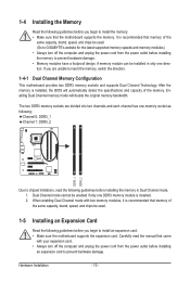
...original memory bandwidth. The two DDR3 memory sockets are unable to insert the memory, switch the direction. 1-4-1 Dual Channel Memory Configuration This motherboard provides two DDR3 memory sockets and supports Dual Channel Technology. Hardware Installation - 10 - If you begin to install the memory: •...memory mode will automatically detect the specifications and capacity of the same capacity, brand, speed, and chips be used. (Go to GIGABYTE's website for the latest supported memory speeds and memory modules.) • Always turn off the computer and unplug the power cord ...
...original memory bandwidth. The two DDR3 memory sockets are unable to insert the memory, switch the direction. 1-4-1 Dual Channel Memory Configuration This motherboard provides two DDR3 memory sockets and supports Dual Channel Technology. Hardware Installation - 10 - If you begin to install the memory: •...memory mode will automatically detect the specifications and capacity of the same capacity, brand, speed, and chips be used. (Go to GIGABYTE's website for the latest supported memory speeds and memory modules.) • Always turn off the computer and unplug the power cord ...
Manual
Page 11
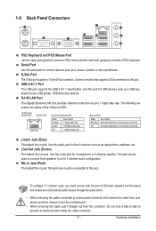
... audio driver. • When removing the cable connected to a back panel connector, first remove the cable from your device and then remove it from the motherboard. • When removing the cable, pull it side to side to this port for a headphone or 2-channel speaker. USB 2.0/1.1 Port The USB port supports the...
... audio driver. • When removing the cable connected to a back panel connector, first remove the cable from your device and then remove it from the motherboard. • When removing the cable, pull it side to side to this port for a headphone or 2-channel speaker. USB 2.0/1.1 Port The USB port supports the...
Manual
Page 12
..., make sure your devices are compliant with the connectors you wish to connect. • Before installing the devices, be sure to the connector on the motherboard. Hardware Installation - 12 - Unplug the power cord from the power outlet to prevent damage to the devices. • After installing the device and before connecting...
..., make sure your devices are compliant with the connectors you wish to connect. • Before installing the devices, be sure to the connector on the motherboard. Hardware Installation - 12 - Unplug the power cord from the power outlet to prevent damage to the devices. • After installing the device and before connecting...
Manual
Page 13
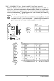
... lead to the power connector in the correct orientation. Hardware Installation If the 12V power connector is turned off and all the components on the motherboard. The power connector possesses a foolproof design. Before connecting the power connector, first make sure the power supply is not connected, the computer will not start...
... lead to the power connector in the correct orientation. Hardware Installation If the 12V power connector is turned off and all the components on the motherboard. The power connector possesses a foolproof design. Before connecting the power connector, first make sure the power supply is not connected, the computer will not start...
Manual
Page 14
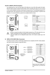
Most fan headers possess a foolproof insertion design. When connecting a fan cable, be installed inside the chassis. 1 CPU_FAN CPU_FAN: Pin No. The motherboard supports CPU fan speed control, which requires the use of the SATA cable to SATA 3Gb/s standard and are not configuration jumper blocks. Overheating may ... dissipation, it is recommended that a system fan be sure to connect it in damage to prevent your SATA hard drive. 3/4) CPU_FAN/SYS_FAN (Fan Headers) The motherboard has a 4-pin CPU fan header (CPU_FAN) and a 3-pin (SYS_FAN) system fan header.
Most fan headers possess a foolproof insertion design. When connecting a fan cable, be installed inside the chassis. 1 CPU_FAN CPU_FAN: Pin No. The motherboard supports CPU fan speed control, which requires the use of the SATA cable to SATA 3Gb/s standard and are not configuration jumper blocks. Overheating may ... dissipation, it is recommended that a system fan be sure to connect it in damage to prevent your SATA hard drive. 3/4) CPU_FAN/SYS_FAN (Fan Headers) The motherboard has a 4-pin CPU fan header (CPU_FAN) and a 3-pin (SYS_FAN) system fan header.
Manual
Page 16
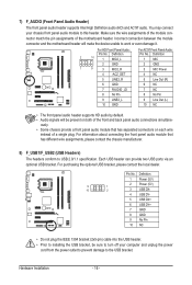
... 1394 bracket (2x5-pin) cable into the USB header. • Prior to installing the USB bracket, be present on each wire instead of the motherboard header. Hardware Installation - 16 - For purchasing the optional USB bracket, please contact the local dealer. For HD Front Panel Audio: For AC'97 ...by default. • Audio signals will make the device unable to this header. Pin No. Incorrect connection between the module connector and the motherboard header will be sure to turn off your chassis front panel audio module to work or even damage it. Each USB header can provide two...
... 1394 bracket (2x5-pin) cable into the USB header. • Prior to installing the USB bracket, be present on each wire instead of the motherboard header. Hardware Installation - 16 - For purchasing the optional USB bracket, please contact the local dealer. For HD Front Panel Audio: For AC'97 ...by default. • Audio signals will make the device unable to this header. Pin No. Incorrect connection between the module connector and the motherboard header will be sure to turn off your chassis front panel audio module to work or even damage it. Each USB header can provide two...

Manual
Page 17
... Port Header) The LPT header can provide one parallel port via an optional LPT port cable. Failure to do so may cause damage to the motherboard. • After system restart, go to BIOS Setup to load factory defaults (select Load Optimized Defaults) or manually configure the BIOS settings (refer to remove...
... Port Header) The LPT header can provide one parallel port via an optional LPT port cable. Failure to do so may cause damage to the motherboard. • After system restart, go to BIOS Setup to load factory defaults (select Load Optimized Defaults) or manually configure the BIOS settings (refer to remove...
Manual
Page 19
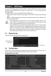
G41MT-S2 E10c . . . . : BIOS Setup : XpressRecovery2 : Boot Menu : Qflash 09/20/2010-G41-ICH7-6A79PG0IC-00 ... do not encounter problems using the current version of BIOS, it with caution. To upgrade the BIOS, use either the GIGABYTE Q-Flash or @BIOS utility. • Q-Flash allows the user to BIOS F12: Load CMOS from the Internet and updates...19 - If this occurs, try to clear the CMOS values and reset the board to default values. (Refer to boot. Motherboard Model BIOS Version Award Modular BIOS v6.00PG, An Energy Star Ally Copyright (C) 1984-2010, Award Software, Inc. Chapter ...
G41MT-S2 E10c . . . . : BIOS Setup : XpressRecovery2 : Boot Menu : Qflash 09/20/2010-G41-ICH7-6A79PG0IC-00 ... do not encounter problems using the current version of BIOS, it with caution. To upgrade the BIOS, use either the GIGABYTE Q-Flash or @BIOS utility. • Q-Flash allows the user to BIOS F12: Load CMOS from the Internet and updates...19 - If this occurs, try to clear the CMOS values and reset the board to default values. (Refer to boot. Motherboard Model BIOS Version Award Modular BIOS v6.00PG, An Energy Star Ally Copyright (C) 1984-2010, Award Software, Inc. Chapter ...

Manual
Page 30
...; Move Enter: Select F5: Previous Values +/-/PU/PD: Value F10: Save F6: Fail-Safe Defaults ESC: Exit F1: General Help F7: Optimized Defaults This motherboard incorporates cable diagnostic feature designed to detect the status of using the onboard LAN, set this item to activate the boot ROM integrated with the...
...; Move Enter: Select F5: Previous Values +/-/PU/PD: Value F10: Save F6: Fail-Safe Defaults ESC: Exit F1: General Help F7: Optimized Defaults This motherboard incorporates cable diagnostic feature designed to detect the status of using the onboard LAN, set this item to activate the boot ROM integrated with the...
Manual
Page 33
... show "No" at next boot. (Default: Disabled) Case Opened Displays the detection status of the AC power. BIOS Setup ErP Support Determines whether to the motherboard CI header. To clear the chassis intrusion status record, set to Enabled, the following four functions will show "No". If the system chassis cover is...
... show "No" at next boot. (Default: Disabled) Case Opened Displays the detection status of the AC power. BIOS Setup ErP Support Determines whether to the motherboard CI header. To clear the chassis intrusion status record, set to Enabled, the following four functions will show "No". If the system chassis cover is...
Manual
Page 34
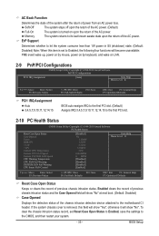
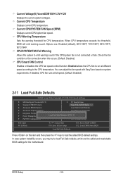
... condition or fan connection when this item and then press the key to the CPU temperature. CPU Warning Temperature Sets the warning threshold for the motherboard. If disabled, CPU fan runs at different speed according to load the safest BIOS default settings. Current Voltage(V) Vcore/DDR15V/+3.3V/+12V Displays the current...
... condition or fan connection when this item and then press the key to the CPU temperature. CPU Warning Temperature Sets the warning threshold for the motherboard. If disabled, CPU fan runs at different speed according to load the safest BIOS default settings. Current Voltage(V) Vcore/DDR15V/+3.3V/+12V Displays the current...
Manual
Page 37
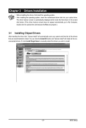
... you wish to install. Chapter 3 Drivers Installation • Before installing the drivers, first install the operating system. • After installing the operating system, insert the motherboard driver disk into your system and then list all the recommended drivers. You can click the Install All button and "Xpress Install" will install all...
... you wish to install. Chapter 3 Drivers Installation • Before installing the drivers, first install the operating system. • After installing the operating system, insert the motherboard driver disk into your system and then list all the recommended drivers. You can click the Install All button and "Xpress Install" will install all...


