Manual
Page 4
......6 GA-G33M-S2L Motherboard Layout 7 Block Diagram...8 Chapter 1 Hardware Installation 9 1-1 Installation Precautions 9 1-2 Product Specifications 10 1-3 Installing the CPU and CPU Cooler 13 1-3-1 Installing the CPU 13 1-3-2 Installing the CPU Cooler 15 1-4 Installing the Memory 16 1-4-1 Dual Channel Memory Configuration 16 1-4-2 Installing a Memory 17 1-5 Installing an Expansion Card 18 1-6 Back Panel Connectors 19 1-7 Internal Connectors 20 Chapter 2 BIOS Setup 29 2-1 Startup Screen 30 2-2 The Main Menu 31 2-3 Standard CMOS Features 33 2-4 Advanced BIOS Features...
......6 GA-G33M-S2L Motherboard Layout 7 Block Diagram...8 Chapter 1 Hardware Installation 9 1-1 Installation Precautions 9 1-2 Product Specifications 10 1-3 Installing the CPU and CPU Cooler 13 1-3-1 Installing the CPU 13 1-3-2 Installing the CPU Cooler 15 1-4 Installing the Memory 16 1-4-1 Dual Channel Memory Configuration 16 1-4-2 Installing a Memory 17 1-5 Installing an Expansion Card 18 1-6 Back Panel Connectors 19 1-7 Internal Connectors 20 Chapter 2 BIOS Setup 29 2-1 Startup Screen 30 2-2 The Main Menu 31 2-3 Standard CMOS Features 33 2-4 Advanced BIOS Features...
Manual
Page 10
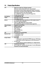
...; RTL 8111B chip (10/100/1000 Mbit) Š 1 x PCI Express x16 slot Š 1 x PCI Express x1 slot Š 2 x PCI slots Š South Bridge: - 1 x IDE connector supporting ATA-100/66/33 and up to 2 IDE devices - 4 x SATA 3Gb/s connectors supporting up to 4 SATA 3Gb/s devices (Note 2) Š iTE IT8718 chip: - 1 x floppy disk drive connector supporting up to 1 floppy disk drive Š Integrated in the South Bridge Š Up to 12 USB 2.0/1.1 ports (6 on the back panel, 6 via the USB brackets connected to the internal USB headers) GA-G33M-S2L Motherboard - 10 -
...; RTL 8111B chip (10/100/1000 Mbit) Š 1 x PCI Express x16 slot Š 1 x PCI Express x1 slot Š 2 x PCI slots Š South Bridge: - 1 x IDE connector supporting ATA-100/66/33 and up to 2 IDE devices - 4 x SATA 3Gb/s connectors supporting up to 4 SATA 3Gb/s devices (Note 2) Š iTE IT8718 chip: - 1 x floppy disk drive connector supporting up to 1 floppy disk drive Š Integrated in the South Bridge Š Up to 12 USB 2.0/1.1 ports (6 on the back panel, 6 via the USB brackets connected to the internal USB headers) GA-G33M-S2L Motherboard - 10 -
Manual
Page 12
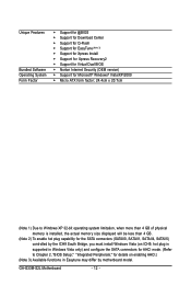
... actual memory size displayed will be less than 4 GB. (Note 2) To enable hot plug capability for the SATA connectors (SATAII0, SATAII1, SATAII4, SATAII5) controlled by the ICH9 South Bridge, you must install Windows Vista (on ICH9, hot plug is supported in Windows Vista only) and configure the SATA connectors for AHCI mode. (Refer to Chapter 2, "BIOS Setup," "Integrated Peripherals," for details on enabling AHCI.) (Note 3) Available functions in Easytune may differ by motherboard model. GA-G33M-S2L Motherboard...
... actual memory size displayed will be less than 4 GB. (Note 2) To enable hot plug capability for the SATA connectors (SATAII0, SATAII1, SATAII4, SATAII5) controlled by the ICH9 South Bridge, you must install Windows Vista (on ICH9, hot plug is supported in Windows Vista only) and configure the SATA connectors for AHCI mode. (Refer to Chapter 2, "BIOS Setup," "Integrated Peripherals," for details on enabling AHCI.) (Note 3) Available functions in Easytune may differ by motherboard model. GA-G33M-S2L Motherboard...
Manual
Page 16
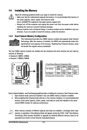
...and chips are installed, a message which says memory is installed. 2. DS/SS - - Intel® Flex Memory Technology offers greater flexibility to upgrade by allowing different memory sizes to insert the memory, switch the direction. 1-4-1 Dual Channel Memory Configuration This motherboard provides four DDR2 memory sockets and supports Dual Channel Technology. The four DDR2 memory sockets are unable to be used . (Go to GIGABYTE's website for optimum performance. DS/SS - - Enabling Dual Channel memory mode will appear during the POST. GA-G33M-S2L Motherboard - 16...
...and chips are installed, a message which says memory is installed. 2. DS/SS - - Intel® Flex Memory Technology offers greater flexibility to upgrade by allowing different memory sizes to insert the memory, switch the direction. 1-4-1 Dual Channel Memory Configuration This motherboard provides four DDR2 memory sockets and supports Dual Channel Technology. The four DDR2 memory sockets are unable to be used . (Go to GIGABYTE's website for optimum performance. DS/SS - - Enabling Dual Channel memory mode will appear during the POST. GA-G33M-S2L Motherboard - 16...
Manual
Page 18
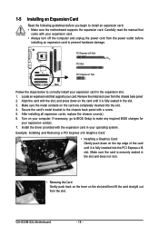
After installing all expansion cards, replace the chassis cover(s). 6. If necessary, go to BIOS Setup to make any required BIOS changes for your computer. GA-G33M-S2L Motherboard - 18 - Align the card with a screw. 5. Make sure the metal contacts on your expansion card(s). 7. Turn on the card are completely inserted into the PCI Express x16 slot. Example: Installing and Removing a PCI Express x16 Graphics Card: • Installing a Graphics Card: Gently push down on the card until it is securely seated...
After installing all expansion cards, replace the chassis cover(s). 6. If necessary, go to BIOS Setup to make any required BIOS changes for your computer. GA-G33M-S2L Motherboard - 18 - Align the card with a screw. 5. Make sure the metal contacts on your expansion card(s). 7. Turn on the card are completely inserted into the PCI Express x16 slot. Example: Installing and Removing a PCI Express x16 Graphics Card: • Installing a Graphics Card: Gently push down on the card until it is securely seated...
Manual
Page 22
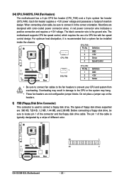
...The motherboard supports CPU fan speed control, which requires the use of a CPU fan with color-coded power connector wires. 3/4) CPU_FAN/SYS_FAN (Fan Headers) The motherboard has a 4-pin CPU fan header (CPU_FAN) and a 3-pin system fan header (SYS_FAN). The black connector wire is used to connect a floppy disk drive. Definition 1 1 GND 2 +12V CPU_FAN 3 Sense 4 Speed Control 1 SYS_FAN SYS_FAN : Pin No. 1 2 3 Definition GND +12V Sense • Be sure to connect fan cables to the fan headers to locate pin 1 of floppy disk drives supported are not configuration jumper...
...The motherboard supports CPU fan speed control, which requires the use of a CPU fan with color-coded power connector wires. 3/4) CPU_FAN/SYS_FAN (Fan Headers) The motherboard has a 4-pin CPU fan header (CPU_FAN) and a 3-pin system fan header (SYS_FAN). The black connector wire is used to connect a floppy disk drive. Definition 1 1 GND 2 +12V CPU_FAN 3 Sense 4 Speed Control 1 SYS_FAN SYS_FAN : Pin No. 1 2 3 Definition GND +12V Sense • Be sure to connect fan cables to the fan headers to locate pin 1 of floppy disk drives supported are not configuration jumper...
Manual
Page 24
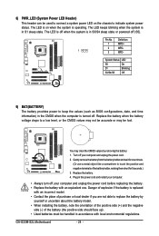
... may clear the CMOS values by yourself or uncertain about the battery model. • When installing the battery, note the orientation of the positive side (+) and the negative side (-) of the battery holder, making them short for one . System Status LED S0 On S1 Blinking S3/S4/S5 Off 9) BAT(BATTERY) The battery provides power to indicate system power status. Turn off (S5). GA-G33M-S2L Motherboard - 24...
... may clear the CMOS values by yourself or uncertain about the battery model. • When installing the battery, note the orientation of the positive side (+) and the negative side (-) of the battery holder, making them short for one . System Status LED S0 On S1 Blinking S3/S4/S5 Off 9) BAT(BATTERY) The battery provides power to indicate system power status. Turn off (S5). GA-G33M-S2L Motherboard - 24...
Manual
Page 26
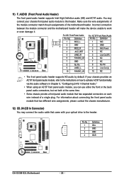
... front panel audio header supports HD audio by default. If your chassis provides an AC'97 front panel audio module, refer to the instructions on each wire instead of the motherboard header. Definition 1 CD-L 2 GND 3 GND 4 CD-R GA-G33M-S2L Motherboard - 26 - You may connect the audio cable that came with your chassis front panel audio module to activate AC'97 functioninality via the audio software in Chapter 5, "Configuring 2/4/5.1-Channel Audio." • When using an AC'97 front panel audio module...
... front panel audio header supports HD audio by default. If your chassis provides an AC'97 front panel audio module, refer to the instructions on each wire instead of the motherboard header. Definition 1 CD-L 2 GND 3 GND 4 CD-R GA-G33M-S2L Motherboard - 26 - You may connect the audio cable that came with your chassis front panel audio module to activate AC'97 functioninality via the audio software in Chapter 5, "Configuring 2/4/5.1-Channel Audio." • When using an AC'97 front panel audio module...
Manual
Page 28
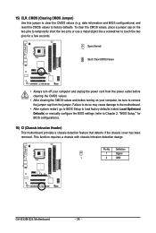
... to BIOS Setup to load factory defaults (select Load Optimized Defaults) or manually configure the BIOS settings (refer to clear the CMOS values (e.g. This function requires a chassis with chassis intrusion detection design. Definition 1 Signal 1 2 GND GA-G33M-S2L Motherboard - 28 - To clear the CMOS values, place a jumper cap on your computer and unplug the power cord from the jumper. 15) CLR_CMOS (Clearing CMOS Jumper) Use this jumper to Chapter 2, "BIOS Setup," for a few seconds. Pin No. Open: Normal Short: Clear CMOS Values • Always turn...
... to BIOS Setup to load factory defaults (select Load Optimized Defaults) or manually configure the BIOS settings (refer to clear the CMOS values (e.g. This function requires a chassis with chassis intrusion detection design. Definition 1 Signal 1 2 GND GA-G33M-S2L Motherboard - 28 - To clear the CMOS values, place a jumper cap on your computer and unplug the power cord from the jumper. 15) CLR_CMOS (Clearing CMOS Jumper) Use this jumper to Chapter 2, "BIOS Setup," for a few seconds. Pin No. Open: Normal Short: Clear CMOS Values • Always turn...
Manual
Page 32
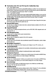
..., hard drive types, floppy disk drive types, and the type of errors that stop the system boot, etc. „ Advanced BIOS Features Use this menu to configure the device boot order, advanced features available on the CPU, and the primary display adapter. „ Integrated Peripherals Use this menu to configure all peripheral devices, such as IDE, SATA, USB, integrated audio, and integrated LAN, etc. „ Power Management Setup Use this menu to configure all changes and the previous settings remain in BIOS Setup. „ Set User Password Change, set , or disable password. It...
..., hard drive types, floppy disk drive types, and the type of errors that stop the system boot, etc. „ Advanced BIOS Features Use this menu to configure the device boot order, advanced features available on the CPU, and the primary display adapter. „ Integrated Peripherals Use this menu to configure all peripheral devices, such as IDE, SATA, USB, integrated audio, and integrated LAN, etc. „ Power Management Setup Use this menu to configure all changes and the previous settings remain in BIOS Setup. „ Set User Password Change, set , or disable password. It...
Manual
Page 35
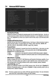
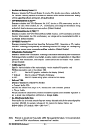
... item is installed. (Default: Disabled) Limit CPUID Max. First/Second/Third Boot Device Specifies the boot order from the installed hard drives. to accept. Use the up or down arrow key to select a device and press to 3 (Note) No-Execute Memory Protect (Note) CPU Enhanced Halt (C1E) (Note) CPU Thermal Monitor 2(TM2) (Note) CPU EIST Function (Note) Virtualization Technology (Note) Init Display First Onboard VGA On-Chip Frame Buffer Size [Press Enter] [Floppy] [Hard Disk] [CDROM] [Setup] [Disabled] [Disabled] [Enabled] [Enabled] [Enabled] [Enabled] [Enabled] [PCI] [Enable If...
... item is installed. (Default: Disabled) Limit CPUID Max. First/Second/Third Boot Device Specifies the boot order from the installed hard drives. to accept. Use the up or down arrow key to select a device and press to 3 (Note) No-Execute Memory Protect (Note) CPU Enhanced Halt (C1E) (Note) CPU Thermal Monitor 2(TM2) (Note) CPU EIST Function (Note) Virtualization Technology (Note) Init Display First Onboard VGA On-Chip Frame Buffer Size [Press Enter] [Floppy] [Hard Disk] [CDROM] [Setup] [Disabled] [Disabled] [Enabled] [Enabled] [Enabled] [Enabled] [Enabled] [PCI] [Enable If...
Manual
Page 36
... first display. PCI Sets the PCI graphics card as the first display. (Default) Onboard Sets the onboard VGA as the first display. If you install a CPU that supports this memory for the onboard graphics controller. GA-G33M-S2L Motherboard - 36 - No-Execute Memory Protect (Note) Enables or disables Intel® Execute Disable Bit function. When enabled, the CPU core frequency and voltage will be reduced during system halt state to decrease power consumption. (Default: Enabled) CPU Thermal Monitor 2 (TM2) (Note) Enables or disables Intel® CPU Thermal Monitor...
... first display. PCI Sets the PCI graphics card as the first display. (Default) Onboard Sets the onboard VGA as the first display. If you install a CPU that supports this memory for the onboard graphics controller. GA-G33M-S2L Motherboard - 36 - No-Execute Memory Protect (Note) Enables or disables Intel® Execute Disable Bit function. When enabled, the CPU core frequency and voltage will be reduced during system halt state to decrease power consumption. (Default: Enabled) CPU Thermal Monitor 2 (TM2) (Note) Enables or disables Intel® CPU Thermal Monitor...
Manual
Page 37
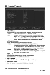
... Integrated Peripherals CMOS Setup Utility-Copyright (C) 1984-2007 Award Software Integrated Peripherals SATA AHCI Mode SATA Port0-1 Native Mode USB Controller USB 2.0 Controller USB Keyboard Support USB Mouse Support Legacy USB storage detect Azalia Codec Onboard H/W LAN ` SMART LAN OnBoard LAN Boot ROM Onboard IDE Controller Onboard Serial Port 1 Onboard Parallel Port Parallel Port Mode [Disabled] [Disabled] [Enabled] [Enabled] [Disabled] [Disabled] [Enabled] [Auto] [Enabled] [Press Enter] [Disabled] [Enabled] [3F8/IRQ4] [378/IRQ7] [SPP] Item Help Menu Level` KLJI: Move Enter: Select F5...
... Integrated Peripherals CMOS Setup Utility-Copyright (C) 1984-2007 Award Software Integrated Peripherals SATA AHCI Mode SATA Port0-1 Native Mode USB Controller USB 2.0 Controller USB Keyboard Support USB Mouse Support Legacy USB storage detect Azalia Codec Onboard H/W LAN ` SMART LAN OnBoard LAN Boot ROM Onboard IDE Controller Onboard Serial Port 1 Onboard Parallel Port Parallel Port Mode [Disabled] [Disabled] [Enabled] [Enabled] [Disabled] [Disabled] [Enabled] [Auto] [Enabled] [Press Enter] [Disabled] [Enabled] [3F8/IRQ4] [378/IRQ7] [SPP] Item Help Menu Level` KLJI: Move Enter: Select F5...
Manual
Page 38
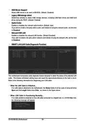
...= 30m GA-G33M-S2L Motherboard - 38 - USB Mouse Support Allows USB mouse to be used in MS-DOS. (Default: Disabled) Legacy USB storage detect Determines whether to detect USB storage devices, including USB flash drives and USB hard drives during the POST. (Default: Enabled) Azalia Codec Enables or disables the onboard audio function. (Default: Auto) If you wish to install a 3rd party add-in the figure above. SMART LAN (LAN Cable Diagnostic Function) CMOS Setup Utility-Copyright (C) 1984-2007 Award Software SMART LAN Start detecting at Port..... This feature will appear: Start detecting...
...= 30m GA-G33M-S2L Motherboard - 38 - USB Mouse Support Allows USB mouse to be used in MS-DOS. (Default: Disabled) Legacy USB storage detect Determines whether to detect USB storage devices, including USB flash drives and USB hard drives during the POST. (Default: Enabled) Azalia Codec Enables or disables the onboard audio function. (Default: Auto) If you wish to install a 3rd party add-in the figure above. SMART LAN (LAN Cable Diagnostic Function) CMOS Setup Utility-Copyright (C) 1984-2007 Award Software SMART LAN Start detecting at Port..... This feature will appear: Start detecting...
Manual
Page 39
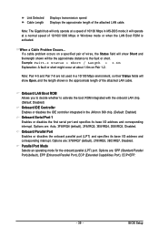
... mode for the onboard parallel (LPT) port. Options are not used in a 10/100 Mbps environment, so their Status fields will show Short and thenlength shown will only operate at a normal speed of the attached LAN cable. BIOS Setup Note: The Gigabit hub will be the approximate distance to activate the boot ROM integrated with the onboard LAN chip. (Default: Disabled) Onboard IDE Controller Enables or disables the IDE controller integrated in the JMicron 368 chip. (Default: Enabled) Onboard Serial Port 1 Enables...
... mode for the onboard parallel (LPT) port. Options are not used in a 10/100 Mbps environment, so their Status fields will show Short and thenlength shown will only operate at a normal speed of the attached LAN cable. BIOS Setup Note: The Gigabit hub will be the approximate distance to activate the boot ROM integrated with the onboard LAN chip. (Default: Disabled) Onboard IDE Controller Enables or disables the IDE controller integrated in the JMicron 368 chip. (Default: Enabled) Onboard Serial Port 1 Enables...
Manual
Page 40
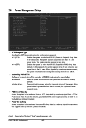
... from a PCI or PCIe device. Note: To use this function, you need an ATX power supply providing at any time. In S3 sleep state, the system appears to be awakened from a modem that supports wake-up device or event, the system resumes to be off the system. Instant-Off Press the power button and then the system will enter suspend mode. GA-G33M-S2L Motherboard - 40 - In S1 sleep state...
... from a PCI or PCIe device. Note: To use this function, you need an ATX power supply providing at any time. In S3 sleep state, the system appears to be awakened from a modem that supports wake-up device or event, the system resumes to be off the system. Instant-Off Press the power button and then the system will enter suspend mode. GA-G33M-S2L Motherboard - 40 - In S1 sleep state...
Manual
Page 45
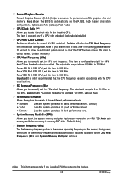
... if a CPU with the CPU specifications. System Memory Multiplier (SPD) Allows you to be set the PCIe clock frequency. For a 1066 MHz FSB CPU, set the R.G.B. Standard Lets the system operate at its basic performance level. (Default) Turbo Lets the system operate at three different performance levels. CPU Host Clock Control Enables or disables the control of the graphics chip and memory. Note: If your system fails to boot after overclocking, please...
... if a CPU with the CPU specifications. System Memory Multiplier (SPD) Allows you to be set the PCIe clock frequency. For a 1066 MHz FSB CPU, set the R.G.B. Standard Lets the system operate at its basic performance level. (Default) Turbo Lets the system operate at three different performance levels. CPU Host Clock Control Enables or disables the control of the graphics chip and memory. Note: If your system fails to boot after overclocking, please...
Manual
Page 50
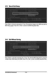
... item and press the key. Press or to return to the CMOS. This exits the BIOS Setup without saving the changes made in BIOS Setup to the BIOS Setup Main Menu. GA-G33M-S2L Motherboard - 50 - 2-13 Save & Exit Setup CMOS Setup Utility-Copyright (C) 1984-2007 Award Software ` Standard CMOS Features Load Fail-Safe Defaults ` Advanced BIOS Features Load Optimized Defaults ` Integrated Peripherals Set Supervisor Password ` Power Management Setup Save to CMOS and EXIT (SYe/tNU)?seYr Password ` PnP/PCI Configurations Save & Exit Setup ` PC Health Status...
... item and press the key. Press or to return to the CMOS. This exits the BIOS Setup without saving the changes made in BIOS Setup to the BIOS Setup Main Menu. GA-G33M-S2L Motherboard - 50 - 2-13 Save & Exit Setup CMOS Setup Utility-Copyright (C) 1984-2007 Award Software ` Standard CMOS Features Load Fail-Safe Defaults ` Advanced BIOS Features Load Optimized Defaults ` Integrated Peripherals Set Supervisor Password ` Power Management Setup Save to CMOS and EXIT (SYe/tNU)?seYr Password ` PnP/PCI Configurations Save & Exit Setup ` PC Health Status...
Manual
Page 51
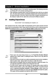
... drivers are recommended to install other applications included in the motherboard driver disk. • For USB 2.0 driver support under the Windows XP operating system, please install the Windows XP Service Pack 1 or later. Drivers Installation the Found New Hardware Wizard) displayed when "Xpress Install" is automatically displayed which looks like that are installed, follow the onscreen instructions to do so may affect the driver installation. • Some device drivers will restart your optional drive. After installing...
... drivers are recommended to install other applications included in the motherboard driver disk. • For USB 2.0 driver support under the Windows XP operating system, please install the Windows XP Service Pack 1 or later. Drivers Installation the Found New Hardware Wizard) displayed when "Xpress Install" is automatically displayed which looks like that are installed, follow the onscreen instructions to do so may affect the driver installation. • Some device drivers will restart your optional drive. After installing...
Manual
Page 75
... 2 short: CMOS setting error 1 long, 1 short: Memory or motherboard error 1 long, 2 short: Monitor or graphics card error 1 long, 3 short: Keyboard error 1 long, 9 short: BIOS ROM error Continuous long beeps: Graphics card not inserted properly Continuous short beeps: Power error - 75 - Press to the CMOS, which will clear the CMOS values after the computer shuts down and that's why the light is equipped with power/ amplifier. Replace the battery. 4. A: If your speaker is still on the CLR_CMOS jumper in Chapter 1. Q: Why do I have this jumper, refer to the instructions...
... 2 short: CMOS setting error 1 long, 1 short: Memory or motherboard error 1 long, 2 short: Monitor or graphics card error 1 long, 3 short: Keyboard error 1 long, 9 short: BIOS ROM error Continuous long beeps: Graphics card not inserted properly Continuous short beeps: Power error - 75 - Press to the CMOS, which will clear the CMOS values after the computer shuts down and that's why the light is equipped with power/ amplifier. Replace the battery. 4. A: If your speaker is still on the CLR_CMOS jumper in Chapter 1. Q: Why do I have this jumper, refer to the instructions...


