Manual
Page 1
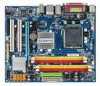
GA-G33M-S2L LGA775 socket motherboard for Intel® CoreTM processor family/ Intel® Pentium® processor family/Intel® Celeron® processor family User's Manual Rev. 1001 12ME-G33MS2L-1001R
GA-G33M-S2L LGA775 socket motherboard for Intel® CoreTM processor family/ Intel® Pentium® processor family/Intel® Celeron® processor family User's Manual Rev. 1001 12ME-G33MS2L-1001R
Manual
Page 3
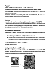
... In order to assist in this : "REV: X.X." Check your motherboard looks like this manual may be made by GIGABYTE without GIGABYTE's prior written permission. is exclusively licensed to the specifications and features in the use GIGABYTE's unique features, read the User's Manual. „ For instructions on your motherboard revision before updating motherboard BIOS, drivers, or...
... In order to assist in this : "REV: X.X." Check your motherboard looks like this manual may be made by GIGABYTE without GIGABYTE's prior written permission. is exclusively licensed to the specifications and features in the use GIGABYTE's unique features, read the User's Manual. „ For instructions on your motherboard revision before updating motherboard BIOS, drivers, or...
Manual
Page 6
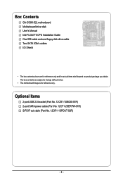
The box contents are for reference only. Optional Items 2-port USB 2.0 bracket (Part No. 12CR1-1UB030-51R) 2-port SATA power cable (Part No. 12CF1-2SERPW-01R) S/PDIF out cable (Part No. 12CR1-1SPOUT-02R) - 6 - Box Contents GA-G33M-S2L motherboard Motherboard driver disk User's Manual Intel® LGA775 CPU Installation Guide One IDE cable and one floppy disk drive cable Two SATA 3Gb/s cables I/O Shield • The box contents above are subject to change without notice. • The motherboard image is for reference only and the actual items shall depend on product package you obtain.
The box contents are for reference only. Optional Items 2-port USB 2.0 bracket (Part No. 12CR1-1UB030-51R) 2-port SATA power cable (Part No. 12CF1-2SERPW-01R) S/PDIF out cable (Part No. 12CR1-1SPOUT-02R) - 6 - Box Contents GA-G33M-S2L motherboard Motherboard driver disk User's Manual Intel® LGA775 CPU Installation Guide One IDE cable and one floppy disk drive cable Two SATA 3Gb/s cables I/O Shield • The box contents above are subject to change without notice. • The motherboard image is for reference only and the actual items shall depend on product package you obtain.
Manual
Page 9
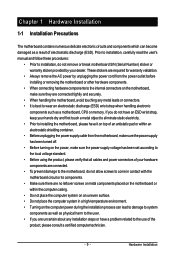
... physical harm to the user. • If you do not have an ESD wrist strap, keep your dealer. Prior to installation, carefully read the user's manual and follow these procedures: • Prior to the use of electrostatic discharge (ESD). Hardware Installation If you are connected tightly and securely. • When handling...
... physical harm to the user. • If you do not have an ESD wrist strap, keep your dealer. Prior to installation, carefully read the user's manual and follow these procedures: • Prior to the use of electrostatic discharge (ESD). Hardware Installation If you are connected tightly and securely. • When handling...
Manual
Page 15
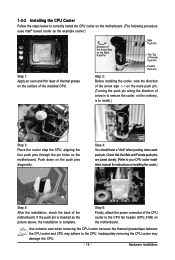
... direction of the arrow sign on the male push pin. (Turning the push pin along the direction of arrow is to your CPU cooler installation manual for instructions on installing the cooler.) Step 5: After the installation, check the back of thermal grease on the motherboard. Check that the Male and Female...
... direction of the arrow sign on the male push pin. (Turning the push pin along the direction of arrow is to your CPU cooler installation manual for instructions on installing the cooler.) Step 5: After the installation, check the back of thermal grease on the motherboard. Check that the Male and Female...
Manual
Page 18
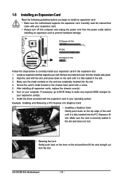
.... 5. Make sure the card is fully inserted into the slot. 4. After installing all expansion cards, replace the chassis cover(s). 6. Carefully read the manual that supports your expansion card(s). 7. GA-G33M-S2L Motherboard - 18 - 1-5 Installing an Expansion Card Read the following guidelines before installing an expansion card to prevent hardware damage. Remove the metal slot...
.... 5. Make sure the card is fully inserted into the slot. 4. After installing all expansion cards, replace the chassis cover(s). 6. Carefully read the manual that supports your expansion card(s). 7. GA-G33M-S2L Motherboard - 18 - 1-5 Installing an Expansion Card Read the following guidelines before installing an expansion card to prevent hardware damage. Remove the metal slot...
Manual
Page 28
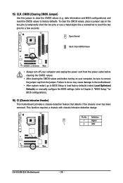
... factory defaults (select Load Optimized Defaults) or manually configure the BIOS settings (refer to touch the two pins for BIOS configurations). 16) CI (Chassis Intrusion Header) This motherboard provides a chassis detection feature that detects if the chassis cover has been removed. Definition 1 Signal 1 2 GND GA-G33M-S2L Motherboard - 28 - To clear the CMOS values...
... factory defaults (select Load Optimized Defaults) or manually configure the BIOS settings (refer to touch the two pins for BIOS configurations). 16) CI (Chassis Intrusion Header) This motherboard provides a chassis detection feature that detects if the chassis cover has been removed. Definition 1 Signal 1 2 GND GA-G33M-S2L Motherboard - 28 - To clear the CMOS values...
Manual
Page 33
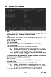
...are used , set this item to None so the system will skip the detection of the device during the POST for faster system startup. • Manual Allows you to None so the system will skip the detection of the hard drive when the hard drive access mode is set the time...(default), Large. - 33 - BIOS Setup For example, 1 p.m. Select the desired field and use the up arrow or down arrow key to set this item to manually enter the specifications of the device during the POST for faster system startup. is week (read-only), month, date and year. Access Mode Sets the...
...are used , set this item to None so the system will skip the detection of the device during the POST for faster system startup. • Manual Allows you to None so the system will skip the detection of the hard drive when the hard drive access mode is set the time...(default), Large. - 33 - BIOS Setup For example, 1 p.m. Select the desired field and use the up arrow or down arrow key to set this item to manually enter the specifications of the device during the POST for faster system startup. is week (read-only), month, date and year. Access Mode Sets the...
Manual
Page 34
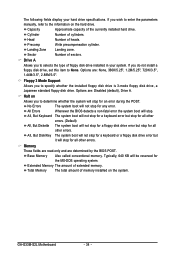
Cylinder Number of heads. If you wish to enter the parameters manually, refer to the information on the hard drive. Halt on the system. All Errors Whenever the BIOS detects a non-fatal error the system boot will .../5.25", 720K/3.5", 1.44M/3.5", 2.88M/3.5". The following fields display your system. Landing Zone Landing zone. Options are: Disabled (default), Drive A. Base Memory Also called conventional memory. GA-G33M-S2L Motherboard - 34 -
Cylinder Number of heads. If you wish to enter the parameters manually, refer to the information on the hard drive. Halt on the system. All Errors Whenever the BIOS detects a non-fatal error the system boot will .../5.25", 720K/3.5", 1.44M/3.5", 2.88M/3.5". The following fields display your system. Landing Zone Landing zone. Options are: Disabled (default), Drive A. Base Memory Also called conventional memory. GA-G33M-S2L Motherboard - 34 -
Manual
Page 44
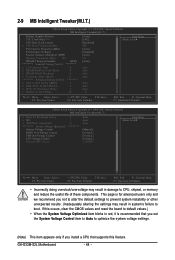
... x tRD x tRD Phase Adjustment ******** System Voltage Optimized System Voltage Control DDR2 OverVoltage Control FSB OverVoltage Control CPU Voltage Control Normal CPU Vcore 2 5 0 ******** Auto Auto Auto [Manual] [Normal] [Normal] [Normal] 1.32500V Item Help Menu Level` KLJI: Move Enter: Select F5: Previous Values +/-/PU/PD: Value F10: Save F6: Fail-Safe Defaults ESC... result in system's failure to CPU, chipset, or memory and reduce the useful life of these components. This page is recommended that supports this feature. GA-G33M-S2L Motherboard - 44 -
... x tRD x tRD Phase Adjustment ******** System Voltage Optimized System Voltage Control DDR2 OverVoltage Control FSB OverVoltage Control CPU Voltage Control Normal CPU Vcore 2 5 0 ******** Auto Auto Auto [Manual] [Normal] [Normal] [Normal] 1.32500V Item Help Menu Level` KLJI: Move Enter: Select F5: Previous Values +/-/PU/PD: Value F10: Save F6: Fail-Safe Defaults ESC... result in system's failure to CPU, chipset, or memory and reduce the useful life of these components. This page is recommended that supports this feature. GA-G33M-S2L Motherboard - 44 -
Manual
Page 45
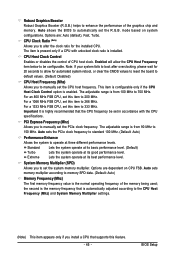
...to be configurable. Auto sets the PCIe clock frequency to standard 100 MHz. (Default: Auto) Performance Enhance Allows the system to manually set the system memory multiplier. Standard Lets the system operate at its basic performance level. (Default) Turbo Lets the system operate ... are dependent on system configurations. Extreme Lets the system operate at its good performance level. The adjustable range is automatically adjusted according to manually set the R.G.B. CPU Clock Ratio (Note) Allows you to the CPU Host Frequency (Mhz) and System Memory Multiplier settings. (Note)...
...to be configurable. Auto sets the PCIe clock frequency to standard 100 MHz. (Default: Auto) Performance Enhance Allows the system to manually set the system memory multiplier. Standard Lets the system operate at its basic performance level. (Default) Turbo Lets the system operate ... are dependent on system configurations. Extreme Lets the system operate at its good performance level. The adjustable range is automatically adjusted according to manually set the R.G.B. CPU Clock Ratio (Note) Allows you to the CPU Host Frequency (Mhz) and System Memory Multiplier settings. (Note)...

Manual
Page 46
... (default), 1~31. Rank Write To READ Delay Options are : Auto (default), 1~31. tRD Phase Adjustment Options are : Auto (default), Manual. Options are : Auto (default), 1~31. Precharge delay (tRAS) Options are : Auto (default), 1~15. GA-G33M-S2L Motherboard - 46 - Refresh to CAS# Delay Options are : Auto (default), 1~15. DRAM RAS# Precharge Options are : Auto (default...
... (default), 1~31. Rank Write To READ Delay Options are : Auto (default), 1~31. tRD Phase Adjustment Options are : Auto (default), Manual. Options are : Auto (default), 1~31. Precharge delay (tRAS) Options are : Auto (default), 1~15. GA-G33M-S2L Motherboard - 46 - Refresh to CAS# Delay Options are : Auto (default), 1~15. DRAM RAS# Precharge Options are : Auto (default...

Manual
Page 47
...voltages as required. (Default) +0.1V ~ +0.3V Increases FSB voltage by 0.1V to set the CPU voltage. Manual allows all voltage control items below to be configurable. (Default: Manual) DDR2 OverVoltage Control Allows you to your CPU or reduce the useful life of your CPU. - 47 - ...the Front Side Bus voltage. Normal sets the CPU voltage as required. (Default) +0.1V ~ +0.4V Increases memory voltage by 0.1V to manually set the system voltages. System Voltage Control Determines whether to 0.3V at 0.1V increment. Normal Supplies the memory voltage as required. Normal ...
...voltages as required. (Default) +0.1V ~ +0.3V Increases FSB voltage by 0.1V to set the CPU voltage. Manual allows all voltage control items below to be configurable. (Default: Manual) DDR2 OverVoltage Control Allows you to your CPU or reduce the useful life of your CPU. - 47 - ...the Front Side Bus voltage. Normal sets the CPU voltage as required. (Default) +0.1V ~ +0.4V Increases memory voltage by 0.1V to manually set the system voltages. System Voltage Control Determines whether to 0.3V at 0.1V increment. Normal Supplies the memory voltage as required. Normal ...
Manual
Page 53
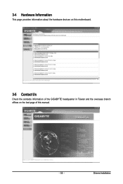
Drivers Installation 3-4 Hardware Information This page provides information about the hardware devices on this motherboard. 3-5 Contact Us Check the contacts information of the GIGABYTE headquarter in Taiwan and the overseas branch offices on the last page of this manual. - 53 -
Drivers Installation 3-4 Hardware Information This page provides information about the hardware devices on this motherboard. 3-5 Contact Us Check the contacts information of the GIGABYTE headquarter in Taiwan and the overseas branch offices on the last page of this manual. - 53 -
Manual
Page 64
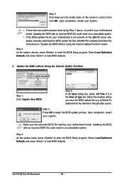
g33ms2l.f1) obtained from GIGABYTE's website and follow the instructions in "Update the BIOS without Using the Internet Update Function Click Update New BIOS Step 1: Click Update New BIOS. Select ... doing Step 3 above, recomfirm your system. • If more than one model is correct, then click OK. GA-G33M-S2L Motherboard - 64 - Step 3: First make sure the model name on the @BIOS server site, please manually download the BIOS update file from the Internet or through other source. Step 2: In the Open dialog box...
g33ms2l.f1) obtained from GIGABYTE's website and follow the instructions in "Update the BIOS without Using the Internet Update Function Click Update New BIOS Step 1: Click Update New BIOS. Select ... doing Step 3 above, recomfirm your system. • If more than one model is correct, then click OK. GA-G33M-S2L Motherboard - 64 - Step 3: First make sure the model name on the @BIOS server site, please manually download the BIOS update file from the Internet or through other source. Step 2: In the Open dialog box...
Manual
Page 78
... disposal of life" product, you can responsibly recycle or reuse most major worldwide safety requirements. GA-G33M-S2L Motherboard - 78 - Restriction of Hazardous Substances (RoHS) Directive Statement GIGABYTE products have been carefully selected to the waste collection centers for any responsibility for errors or omissions...information on how you may contact us at GIGABYTE are continuing our efforts to a third party nor be used equipment must be disposed of harmful substances into the environment and to your product's user's manual and we at the Customer Care number ...
... disposal of life" product, you can responsibly recycle or reuse most major worldwide safety requirements. GA-G33M-S2L Motherboard - 78 - Restriction of Hazardous Substances (RoHS) Directive Statement GIGABYTE products have been carefully selected to the waste collection centers for any responsibility for errors or omissions...information on how you may contact us at GIGABYTE are continuing our efforts to a third party nor be used equipment must be disposed of harmful substances into the environment and to your product's user's manual and we at the Customer Care number ...


