Manual
Page 1
GA-G33M-S2L LGA775 socket motherboard for Intel® CoreTM processor family/ Intel® Pentium® processor family/Intel® Celeron® processor family User's Manual Rev. 1001 12ME-G33MS2L-1001R
GA-G33M-S2L LGA775 socket motherboard for Intel® CoreTM processor family/ Intel® Pentium® processor family/Intel® Celeron® processor family User's Manual Rev. 1001 12ME-G33MS2L-1001R
Manual
Page 2
Motherboard GA-G33M-S2L Oct. 22, 2007 Motherboard GA-G33M-S2L Oct. 22, 2007
Motherboard GA-G33M-S2L Oct. 22, 2007 Motherboard GA-G33M-S2L Oct. 22, 2007
Manual
Page 3
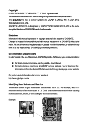
... to the specifications and features in the use of this product, GIGABYTE provides the following types of GIGABYTE. GIGABYTE UNITED INC. Documentation Classifications In order to their respective owners. Check your motherboard looks like this manual may be reproduced, copied, translated, transmitted,... means without prior notice. For product-related information, check on our website at: http://www.gigabyte.com.tw Identifying Your Motherboard Revision The revision number on how to GIGABYTE UNITED INC. sive global distributor of this : "REV: X.X." by any form or by ...
... to the specifications and features in the use of this product, GIGABYTE provides the following types of GIGABYTE. GIGABYTE UNITED INC. Documentation Classifications In order to their respective owners. Check your motherboard looks like this manual may be reproduced, copied, translated, transmitted,... means without prior notice. For product-related information, check on our website at: http://www.gigabyte.com.tw Identifying Your Motherboard Revision The revision number on how to GIGABYTE UNITED INC. sive global distributor of this : "REV: X.X." by any form or by ...
Manual
Page 4
Table of Contents Box Contents ...6 OptionalItems...6 GA-G33M-S2L Motherboard Layout 7 Block Diagram...8 Chapter 1 Hardware Installation 9 1-1 Installation Precautions 9 1-2 Product Specifications 10 1-3 Installing the CPU and CPU Cooler 13 1-3-1 Installing the CPU 13 1-3-2 Installing the CPU ...
Table of Contents Box Contents ...6 OptionalItems...6 GA-G33M-S2L Motherboard Layout 7 Block Diagram...8 Chapter 1 Hardware Installation 9 1-1 Installation Precautions 9 1-2 Product Specifications 10 1-3 Installing the CPU and CPU Cooler 13 1-3-1 Installing the CPU 13 1-3-2 Installing the CPU ...
Manual
Page 6
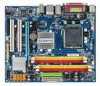
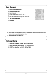
Optional Items 2-port USB 2.0 bracket (Part No. 12CR1-1UB030-51R) 2-port SATA power cable (Part No. 12CF1-2SERPW-01R) S/PDIF out cable (Part No. 12CR1-1SPOUT-02R) - 6 - Box Contents GA-G33M-S2L motherboard Motherboard driver disk User's Manual Intel® LGA775 CPU Installation Guide One IDE cable and one floppy disk drive cable Two SATA 3Gb/s cables I/O Shield • The box contents above are subject to change without notice. • The motherboard image is for reference only and the actual items shall depend on product package you obtain. The box contents are for reference only.
Optional Items 2-port USB 2.0 bracket (Part No. 12CR1-1UB030-51R) 2-port SATA power cable (Part No. 12CF1-2SERPW-01R) S/PDIF out cable (Part No. 12CR1-1SPOUT-02R) - 6 - Box Contents GA-G33M-S2L motherboard Motherboard driver disk User's Manual Intel® LGA775 CPU Installation Guide One IDE cable and one floppy disk drive cable Two SATA 3Gb/s cables I/O Shield • The box contents above are subject to change without notice. • The motherboard image is for reference only and the actual items shall depend on product package you obtain. The box contents are for reference only.
Manual
Page 7
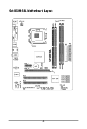
GA-G33M-S2L Motherboard Layout COMA KB_MS ATX_12V LGA775 DDRII1 DDRII2 CPU_FAN LPT VGA USB R_USB IDE ATX CI CLR_CMOS GA-G33M-S2L DDRII3 DDRII4 LAN AUDIO F_AUDIO RTL8111B PCIE_1 PCIE_16 IT8718 PCI1 PCI2 CODEC CD_IN SPDIF_O FDD Intel® G33 BAT MBIOS Intel® ICH9 SATAII0 SATAII1 SATAII4 SATAII5 SYS_FAN PWR_LED F_USB3F_USB2 F_USB1 F_PANEL - 7 -
GA-G33M-S2L Motherboard Layout COMA KB_MS ATX_12V LGA775 DDRII1 DDRII2 CPU_FAN LPT VGA USB R_USB IDE ATX CI CLR_CMOS GA-G33M-S2L DDRII3 DDRII4 LAN AUDIO F_AUDIO RTL8111B PCIE_1 PCIE_16 IT8718 PCI1 PCI2 CODEC CD_IN SPDIF_O FDD Intel® G33 BAT MBIOS Intel® ICH9 SATAII0 SATAII1 SATAII4 SATAII5 SYS_FAN PWR_LED F_USB3F_USB2 F_USB1 F_PANEL - 7 -
Manual
Page 9
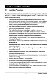
..., please verify that all cables and power connectors of your dealer. Hardware Installation Chapter 1 Hardware Installation 1-1 Installation Precautions The motherboard contains numerous delicate electronic circuits and components which can lead to damage to system components as well as a result of electrostatic discharge... hardware components to the internal connectors on the power, make sure they are connected. • To prevent damage to the motherboard, do not allow screws to come in a high-temperature environment. • Turning on the computer power during the installation process...
..., please verify that all cables and power connectors of your dealer. Hardware Installation Chapter 1 Hardware Installation 1-1 Installation Precautions The motherboard contains numerous delicate electronic circuits and components which can lead to damage to system components as well as a result of electrostatic discharge... hardware components to the internal connectors on the power, make sure they are connected. • To prevent damage to the motherboard, do not allow screws to come in a high-temperature environment. • Turning on the computer power during the installation process...
Manual
Page 10
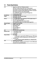
... Extreme Edition/Intel® Pentium® 4 processor/ Intel® Celeron® processor in the LGA 775 package (Go to GIGABYTE's website for the latest CPU support list.) Š L2 cache varies with CPU Š 1333/1066/800 MHz FSB Š... memory (Note 1) Š Dual channel memory architecture Š Support for DDR2 800/667 MHz memory modules (Go to GIGABYTE's website for the latest memory support list.) Š Integrated in the North Bridge Š Realtek ALC662 codec Š High...the back panel, 6 via the USB brackets connected to the internal USB headers) GA-G33M-S2L Motherboard - 10 -
... Extreme Edition/Intel® Pentium® 4 processor/ Intel® Celeron® processor in the LGA 775 package (Go to GIGABYTE's website for the latest CPU support list.) Š L2 cache varies with CPU Š 1333/1066/800 MHz FSB Š... memory (Note 1) Š Dual channel memory architecture Š Support for DDR2 800/667 MHz memory modules (Go to GIGABYTE's website for the latest memory support list.) Š Integrated in the North Bridge Š Realtek ALC662 codec Š High...the back panel, 6 via the USB brackets connected to the internal USB headers) GA-G33M-S2L Motherboard - 10 -
Manual
Page 12
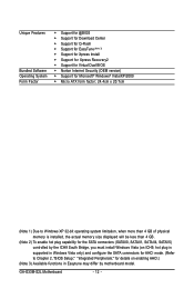
GA-G33M-S2L Motherboard - 12 - Unique Features Bundled Software Operating System Form Factor Š Support for @BIOS Š Support for Download Center Š Support for Q-Flash Š Support for ... SATA connectors for AHCI mode. (Refer to Chapter 2, "BIOS Setup," "Integrated Peripherals," for details on enabling AHCI.) (Note 3) Available functions in Easytune may differ by motherboard model.
GA-G33M-S2L Motherboard - 12 - Unique Features Bundled Software Operating System Form Factor Š Support for @BIOS Š Support for Download Center Š Support for Q-Flash Š Support for ... SATA connectors for AHCI mode. (Refer to Chapter 2, "BIOS Setup," "Integrated Peripherals," for details on enabling AHCI.) (Note 3) Available functions in Easytune may differ by motherboard model.
Manual
Page 13
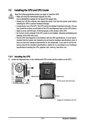
...LGA775 CPU Socket Alignment Key LGA 775 CPU Alignment Key Pin One Corner of the CPU. Locate the alignment keys on the motherboard CPU socket and the notches on the CPU - 13 - Hardware Installation The CPU cannot be set the frequency beyond hardware specifications...your hardware specifications including the CPU, graphics card, memory, hard drive, etc. 1-3-1 Installing the CPU A. mended that the motherboard supports the CPU. (Go to GIGABYTE's website for the peripherals. 1-3 Installing the CPU and CPU Cooler Read the following guidelines before installing the CPU to prevent ...
...LGA775 CPU Socket Alignment Key LGA 775 CPU Alignment Key Pin One Corner of the CPU. Locate the alignment keys on the motherboard CPU socket and the notches on the CPU - 13 - Hardware Installation The CPU cannot be set the frequency beyond hardware specifications...your hardware specifications including the CPU, graphics card, memory, hard drive, etc. 1-3-1 Installing the CPU A. mended that the motherboard supports the CPU. (Go to GIGABYTE's website for the peripherals. 1-3 Installing the CPU and CPU Cooler Read the following guidelines before installing the CPU to prevent ...
Manual
Page 14
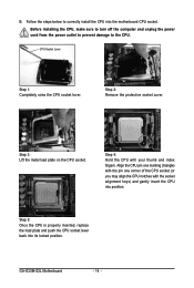
CPU Socket Lever Step 1: Completely raise the CPU socket lever. GA-G33M-S2L Motherboard - 14 - Before installing the CPU, make sure to turn off the computer and unplug the power cord from the power outlet to prevent damage to ... your thumb and index fingers. Step 5: Once the CPU is properly inserted, replace the load plate and push the CPU socket lever back into the motherboard CPU socket. B. Step 4: Hold the CPU with the socket alignment keys) and gently insert the CPU into position. Follow the steps below to the CPU...
CPU Socket Lever Step 1: Completely raise the CPU socket lever. GA-G33M-S2L Motherboard - 14 - Before installing the CPU, make sure to turn off the computer and unplug the power cord from the power outlet to prevent damage to ... your thumb and index fingers. Step 5: Once the CPU is properly inserted, replace the load plate and push the CPU socket lever back into the motherboard CPU socket. B. Step 4: Hold the CPU with the socket alignment keys) and gently insert the CPU into position. Follow the steps below to the CPU...
Manual
Page 15
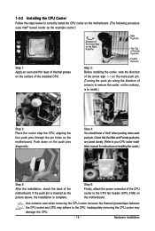
... connector of the CPU cooler to install.) Step 3: Place the cooler atop the CPU, aligning the four push pins through the pin holes on the motherboard. Check that the Male and Female push pins are joined closely. (Refer to correctly install the CPU cooler on the...cooler installation manual for instructions on installing the cooler.) Step 5: After the installation, check the back of the motherboard. Push down each push pin. Step 4: You should hear a "click" when pushing down on the motherboard. If the push pin is inserted as the example cooler.) Step 1: Apply an even and thin layer...
... connector of the CPU cooler to install.) Step 3: Place the cooler atop the CPU, aligning the four push pins through the pin holes on the motherboard. Check that the Male and Female push pins are joined closely. (Refer to correctly install the CPU cooler on the...cooler installation manual for instructions on installing the cooler.) Step 5: After the installation, check the back of the motherboard. Push down each push pin. Step 4: You should hear a "click" when pushing down on the motherboard. If the push pin is inserted as the example cooler.) Step 1: Apply an even and thin layer...
Manual
Page 16
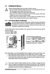
...GIGABYTE's website for optimum performance. DS/SS - - If you begin to prevent hardware damage. • Memory modules have a foolproof design. When enabling Dual Channel mode with two or four memory modules, it is operating in Dual Channel mode. 1. When memory modules of the memory. GA-G33M-S2L Motherboard...No Memory) DDRII1 DDRII2 DDRII3 DDRII4 Due to insert the memory, switch the direction. 1-4-1 Dual Channel Memory Configuration This motherboard provides four DDR2 memory sockets and supports Dual Channel Technology. A memory module can be enabled if only one direction....
...GIGABYTE's website for optimum performance. DS/SS - - If you begin to prevent hardware damage. • Memory modules have a foolproof design. When enabling Dual Channel mode with two or four memory modules, it is operating in Dual Channel mode. 1. When memory modules of the memory. GA-G33M-S2L Motherboard...No Memory) DDRII1 DDRII2 DDRII3 DDRII4 Due to insert the memory, switch the direction. 1-4-1 Dual Channel Memory Configuration This motherboard provides four DDR2 memory sockets and supports Dual Channel Technology. A memory module can be enabled if only one direction....
Manual
Page 17
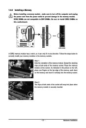
... , make sure to turn off the computer and unplug the power cord from the power outlet to prevent damage to install DDR2 DIMMs on this motherboard. Hardware Installation Spread the retaining clips at both ends of the memory module. As indicated in the picture on the socket.
... , make sure to turn off the computer and unplug the power cord from the power outlet to prevent damage to install DDR2 DIMMs on this motherboard. Hardware Installation Spread the retaining clips at both ends of the memory module. As indicated in the picture on the socket.
Manual
Page 18
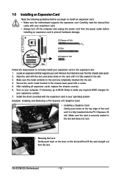
... supports your expansion card(s). 7. Remove the metal slot cover from the power outlet before you begin to install an expansion card: • Make sure the motherboard supports the expansion card. Align the card with your computer. Secure the card's metal bracket to the chassis back panel with the expansion card in... your card. 1-5 Installing an Expansion Card Read the following guidelines before installing an expansion card to prevent hardware damage. Install the driver provided with a screw. 5. GA-G33M-S2L Motherboard - 18 -
... supports your expansion card(s). 7. Remove the metal slot cover from the power outlet before you begin to install an expansion card: • Make sure the motherboard supports the expansion card. Align the card with your computer. Secure the card's metal bracket to the chassis back panel with the expansion card in... your card. 1-5 Installing an Expansion Card Read the following guidelines before installing an expansion card to prevent hardware damage. Install the driver provided with a screw. 5. GA-G33M-S2L Motherboard - 18 -
Manual
Page 19
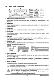
... Data transmission or receiving is occurring Off No data transmission or receiving is also called a printer port. Do not rock it straight out from the motherboard. • When removing the cable, pull it side to side to connect devices such as an optical drive, walkman, etc. 1-6 Back Panel Connectors PS/2 Keyboard...
... Data transmission or receiving is occurring Off No data transmission or receiving is also called a printer port. Do not rock it straight out from the motherboard. • When removing the cable, pull it side to side to connect devices such as an optical drive, walkman, etc. 1-6 Back Panel Connectors PS/2 Keyboard...
Manual
Page 20
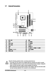
... devices are compliant with the connectors you wish to connect. • Before installing the devices, be sure to turn off the devices and your computer. GA-G33M-S2L Motherboard - 20 - 1-7 Internal Connectors 1 3 6 2 11 15 9 7 12 13 5 4 16 14 8 10 1) ATX_12V 2) ATX 3) CPU_FAN 4) SYS_FAN 5) FDD 6) IDE 7) SATAII0 / 1 / 4 / 5 8) PWR_LED 9) BAT 10) F_PANEL 11) F_AUDIO 12) CD_IN...
... devices are compliant with the connectors you wish to connect. • Before installing the devices, be sure to turn off the devices and your computer. GA-G33M-S2L Motherboard - 20 - 1-7 Internal Connectors 1 3 6 2 11 15 9 7 12 13 5 4 16 14 8 10 1) ATX_12V 2) ATX 3) CPU_FAN 4) SYS_FAN 5) FDD 6) IDE 7) SATAII0 / 1 / 4 / 5 8) PWR_LED 9) BAT 10) F_PANEL 11) F_AUDIO 12) CD_IN...
Manual
Page 21
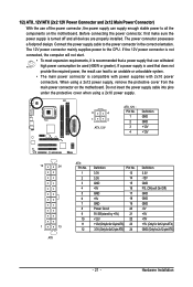
... cable into pins under the protective cover when using a 2x12 power supply, remove the protective cover from the main power connector on the motherboard. Connect the power supply cable to the CPU. The 12V power connector mainly supplies power to the power connector in the correct orientation. ...used that can lead to an unstable or unbootable system. • The main power connector is turned off and all the components on the motherboard. 1/2) ATX_12V/ATX (2x2 12V Power Connector and 2x12 Main Power Connector) With the use of the power connector, the power supply can supply...
... cable into pins under the protective cover when using a 2x12 power supply, remove the protective cover from the main power connector on the motherboard. Connect the power supply cable to the CPU. The 12V power connector mainly supplies power to the power connector in the correct orientation. ...used that can lead to an unstable or unbootable system. • The main power connector is turned off and all the components on the motherboard. 1/2) ATX_12V/ATX (2x2 12V Power Connector and 2x12 Main Power Connector) With the use of the power connector, the power supply can supply...
Manual
Page 22
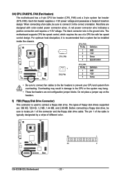
...drives supported are designed with fan speed control design. The black connector wire is typically designated by a stripe of different color. 33 1 34 2 GA-G33M-S2L Motherboard - 22 - A red power connector wire indicates a positive connection and requires a +12V voltage. Overheating may hang. • These fan headers... design. When connecting a fan cable, be sure to connect it is used to connect a floppy disk drive. The motherboard supports CPU fan speed control, which requires the use of the cable is the ground wire. 3/4) CPU_FAN/SYS_FAN (Fan Headers) The...
...drives supported are designed with fan speed control design. The black connector wire is typically designated by a stripe of different color. 33 1 34 2 GA-G33M-S2L Motherboard - 22 - A red power connector wire indicates a positive connection and requires a +12V voltage. Overheating may hang. • These fan headers... design. When connecting a fan cable, be sure to connect it is used to connect a floppy disk drive. The motherboard supports CPU fan speed control, which requires the use of the cable is the ground wire. 3/4) CPU_FAN/SYS_FAN (Fan Headers) The...
Manual
Page 24
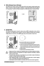
... face up). • Used batteries must be lost. Definition 1 MPD+ 2 MPD- 1 3 MPD- You may be handled in accordance with local environmental regulations. Turn off (S5). GA-G33M-S2L Motherboard - 24 - The LED keeps blinking when the system is in the CMOS when the computer is replaced with an equivalent one minute. (Or use a metal...
... face up). • Used batteries must be lost. Definition 1 MPD+ 2 MPD- 1 3 MPD- You may be handled in accordance with local environmental regulations. Turn off (S5). GA-G33M-S2L Motherboard - 24 - The LED keeps blinking when the system is in the CMOS when the computer is replaced with an equivalent one minute. (Or use a metal...


