
Manual
Page 3
... information, carefully read the User's Manual. For instructions on how to use of this product, GIGABYTE provides the following types of the motherboard is the property of this manual may be reproduced, copied, translated, transmitted, or published in the use GIGABYTE's unique features, read or download the information on/from the Support&Downloads\Motherboard\Technology Guide page on your motherboard revision before updating motherboard BIOS, drivers, or when looking for...
... information, carefully read the User's Manual. For instructions on how to use of this product, GIGABYTE provides the following types of the motherboard is the property of this manual may be reproduced, copied, translated, transmitted, or published in the use GIGABYTE's unique features, read or download the information on/from the Support&Downloads\Motherboard\Technology Guide page on your motherboard revision before updating motherboard BIOS, drivers, or when looking for...
Manual
Page 4
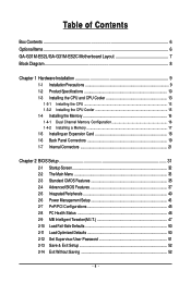
......6 GA-G31M-ES2L/GA-G31M-ES2C Motherboard Layout 7 Block Diagram...8 Chapter 1 Hardware Installation 9 1-1 Installation Precautions 9 1-2 Product Specifications 10 1-3 Installing the CPU and CPU Cooler 13 1-3-1 Installing the CPU 13 1-3-2 Installing the CPU Cooler 15 1-4 Installing the Memory 16 1-4-1 Dual Channel Memory Configuration 16 1-4-2 Installing a Memory 17 1-5 Installing an Expansion Card 18 1-6 Back Panel Connectors 19 1-7 Internal Connectors 21 Chapter 2 BIOS Setup 31 2-1 Startup Screen 32 2-2 The Main Menu 33 2-3 Standard CMOS Features 35 2-4 Advanced BIOS...
......6 GA-G31M-ES2L/GA-G31M-ES2C Motherboard Layout 7 Block Diagram...8 Chapter 1 Hardware Installation 9 1-1 Installation Precautions 9 1-2 Product Specifications 10 1-3 Installing the CPU and CPU Cooler 13 1-3-1 Installing the CPU 13 1-3-2 Installing the CPU Cooler 15 1-4 Installing the Memory 16 1-4-1 Dual Channel Memory Configuration 16 1-4-2 Installing a Memory 17 1-5 Installing an Expansion Card 18 1-6 Back Panel Connectors 19 1-7 Internal Connectors 21 Chapter 2 BIOS Setup 31 2-1 Startup Screen 32 2-2 The Main Menu 33 2-3 Standard CMOS Features 35 2-4 Advanced BIOS...
Manual
Page 10
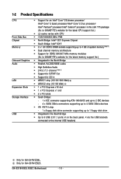
... Mbit) 1 x PCI Express x16 slot 1 x PCI Express x1 slot 2 x PCI slots South Bridge: - 1 x IDE connector supporting ATA-100/66/33 and up to 2 IDE devices - 4 x SATA 3Gb/s connectors supporting up to 4 SATA 3Gb/s devices iTE IT8718 chip: - 1 x floppy disk drive connector supporting up to 1 floppy disk drive Integrated in the South Bridge Up to 8 USB 2.0/1.1 ports (4 on the back panel, 4 via the USB brackets connected to the internal USB headers) Only for GA-G31M-ES2C. Only for GA-G31M-ES2L. GA-G31M-ES2L/ES2C Motherboard - 10 -
... Mbit) 1 x PCI Express x16 slot 1 x PCI Express x1 slot 2 x PCI slots South Bridge: - 1 x IDE connector supporting ATA-100/66/33 and up to 2 IDE devices - 4 x SATA 3Gb/s connectors supporting up to 4 SATA 3Gb/s devices iTE IT8718 chip: - 1 x floppy disk drive connector supporting up to 1 floppy disk drive Integrated in the South Bridge Up to 8 USB 2.0/1.1 ports (4 on the back panel, 4 via the USB brackets connected to the internal USB headers) Only for GA-G31M-ES2C. Only for GA-G31M-ES2L. GA-G31M-ES2L/ES2C Motherboard - 10 -
Manual
Page 12
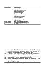
GA-G31M-ES2L/ES2C Motherboard - 12 - For example, 4 GB of memory size will instead be shown as 3.xx GB during system startup. (Note 2) To configure 7.1-channel audio, you need connect with the port of memory is reserved for system usage and therefore the actual memory size is supported will depend on the CPU you install. (Note 4) Available functions in EasyTune may differ by motherboard model. (Note 5) Due to the hardware...
GA-G31M-ES2L/ES2C Motherboard - 12 - For example, 4 GB of memory size will instead be shown as 3.xx GB during system startup. (Note 2) To configure 7.1-channel audio, you need connect with the port of memory is reserved for system usage and therefore the actual memory size is supported will depend on the CPU you install. (Note 4) Available functions in EasyTune may differ by motherboard model. (Note 5) Due to the hardware...
Manual
Page 16
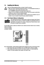
..., speed, and chips be used . GA-G31M-ES2L/ES2C Motherboard - 16 - The two DDR2 memory sockets are unable to prevent hardware damage. • Memory modules have a foolproof design. Enabling Dual Channel memory mode will automatically detect the specifications and capacity of the same capacity, brand, speed, and chips be installed in Dual Channel mode. 1. A memory module can be used . (Go to GIGABYTE's website for the latest memory support list.) • Always turn off the computer and unplug the power cord...
..., speed, and chips be used . GA-G31M-ES2L/ES2C Motherboard - 16 - The two DDR2 memory sockets are unable to prevent hardware damage. • Memory modules have a foolproof design. Enabling Dual Channel memory mode will automatically detect the specifications and capacity of the same capacity, brand, speed, and chips be installed in Dual Channel mode. 1. A memory module can be used . (Go to GIGABYTE's website for the latest memory support list.) • Always turn off the computer and unplug the power cord...
Manual
Page 18
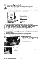
... card to prevent hardware damage. Remove the metal slot cover from the slot. After installing all expansion cards, replace the chassis cover(s). 6. Install the driver provided with the slot, and press down on the slot and then lift the card straight out from the chassis back panel. 2. GA-G31M-ES2L/ES2C Motherboard - 18 - Secure the card's metal bracket to make any required BIOS changes for your operating system. Example: Installing and Removing a PCI Express x16 Graphics Card: • Installing a Graphics Card...
... card to prevent hardware damage. Remove the metal slot cover from the slot. After installing all expansion cards, replace the chassis cover(s). 6. Install the driver provided with the slot, and press down on the slot and then lift the card straight out from the chassis back panel. 2. GA-G31M-ES2L/ES2C Motherboard - 18 - Secure the card's metal bracket to make any required BIOS changes for your operating system. Example: Installing and Removing a PCI Express x16 Graphics Card: • Installing a Graphics Card...
Manual
Page 29
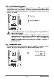
... chassis cover has been removed. Open: Normal Short: Clear CMOS Values • Always turn off your computer, be sure to factory defaults. Pin No. Hardware Installation 15) CLR_CMOS (Clearing CMOS Jumper) Use this jumper to Chapter 2, "BIOS Setup," for a few seconds. Failure to do so may cause damage to the motherboard. • After system restart, go to BIOS Setup to load factory defaults (select Load Optimized Defaults) or manually configure the BIOS settings (refer to clear the CMOS values (e.g. To clear...
... chassis cover has been removed. Open: Normal Short: Clear CMOS Values • Always turn off your computer, be sure to factory defaults. Pin No. Hardware Installation 15) CLR_CMOS (Clearing CMOS Jumper) Use this jumper to Chapter 2, "BIOS Setup," for a few seconds. Failure to do so may cause damage to the motherboard. • After system restart, go to BIOS Setup to load factory defaults (select Load Optimized Defaults) or manually configure the BIOS settings (refer to clear the CMOS values (e.g. To clear...
Manual
Page 34
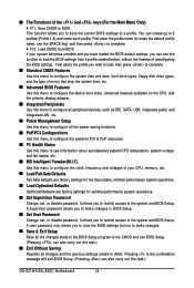
..., hard drive types, floppy disk drive types, and the type of errors that stop the system boot, etc. Advanced BIOS Features Use this menu to configure the device boot order, advanced features available on the CPU, and the primary display adapter. Integrated Peripherals Use this menu to configure all peripheral devices, such as IDE, SATA, USB, integrated audio, and integrated LAN, etc. Power Management Setup Use this menu to configure all the power-saving functions. PnP/PCI Configurations Use this menu to configure the...
..., hard drive types, floppy disk drive types, and the type of errors that stop the system boot, etc. Advanced BIOS Features Use this menu to configure the device boot order, advanced features available on the CPU, and the primary display adapter. Integrated Peripherals Use this menu to configure all peripheral devices, such as IDE, SATA, USB, integrated audio, and integrated LAN, etc. Power Management Setup Use this menu to configure all the power-saving functions. PnP/PCI Configurations Use this menu to configure the...

Manual
Page 35
...; IDE Channel 3 Slave [None] [None] [None] [None] [None] [None] Drive A Floppy 3 Mode Support [1.44M, 3.5"] [Disabled] Halt On [All, But Keyboard] Base Memory Extended Memory Total Memory 640K 510M 512M Move Enter: Select F5: Previous Values +/-/PU/PD: Value F10: Save F6: Fail-Safe Defaults ESC: Exit F1: General Help F7: Optimized Defaults Date Sets the system date. IDE Channel 0 Master/Slave Configure your IDE/SATA devices by using one of the device during the POST...
...; IDE Channel 3 Slave [None] [None] [None] [None] [None] [None] Drive A Floppy 3 Mode Support [1.44M, 3.5"] [Disabled] Halt On [All, But Keyboard] Base Memory Extended Memory Total Memory 640K 510M 512M Move Enter: Select F5: Previous Values +/-/PU/PD: Value F10: Save F6: Fail-Safe Defaults ESC: Exit F1: General Help F7: Optimized Defaults Date Sets the system date. IDE Channel 0 Master/Slave Configure your IDE/SATA devices by using one of the device during the POST...
Manual
Page 37
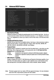
..., USB-ZIP, USB-CDROM, USB-HDD, LAN, Disabled. Use the up or down arrow key to select a hard drive, then press the plus key (or ) or the minus key (or ) to 3 (Note) No-Execute Memory Protect (Note) CPU Enhanced Halt (C1E) (Note) CPU Thermal Monitor 2(TM2) (Note) CPU EIST Function (Note) Virtualization Technology (Note) Init Display First Onboard VGA On-Chip Frame Buffer Size [Press Enter] [Floppy] [Hard Disk] [CDROM] [Setup] [Disabled] [Enabled] [Disabled] [Enabled] [Enabled] [Enabled] [Enabled] [Enabled] [PCI] [Enable If No Ext PEG] [8MB+1~2MB for entering the BIOS Setup...
..., USB-ZIP, USB-CDROM, USB-HDD, LAN, Disabled. Use the up or down arrow key to select a hard drive, then press the plus key (or ) or the minus key (or ) to 3 (Note) No-Execute Memory Protect (Note) CPU Enhanced Halt (C1E) (Note) CPU Thermal Monitor 2(TM2) (Note) CPU EIST Function (Note) Virtualization Technology (Note) Init Display First Onboard VGA On-Chip Frame Buffer Size [Press Enter] [Floppy] [Hard Disk] [CDROM] [Setup] [Disabled] [Enabled] [Disabled] [Enabled] [Enabled] [Enabled] [Enabled] [Enabled] [PCI] [Enable If No Ext PEG] [8MB+1~2MB for entering the BIOS Setup...

Manual
Page 39
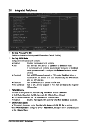
... installed. Options are: 8MB+1~2MB for GTT (default), 1MB+1~2MB for the onboard graphics controller. Onboard VGA Enables or disables the onboard VGA function. MS-DOS, for example, will use only this item to set up a dual view configuration, set this memory for display. BIOS Setup Enable If No Ext PEG Activates the onboard VGA only if no PCI Express VGA card is installed. (Default) Always Enable Always activates the onboard VGA, whether or not a PCI Express card is the total amount of the monitor display from the installed PCI graphics card, PCI Express graphics card...
... installed. Options are: 8MB+1~2MB for GTT (default), 1MB+1~2MB for the onboard graphics controller. Onboard VGA Enables or disables the onboard VGA function. MS-DOS, for example, will use only this item to set up a dual view configuration, set this memory for display. BIOS Setup Enable If No Ext PEG Activates the onboard VGA only if no PCI Express VGA card is installed. (Default) Always Enable Always activates the onboard VGA, whether or not a PCI Express card is the total amount of the monitor display from the installed PCI graphics card, PCI Express graphics card...
Manual
Page 40
.... GA-G31M-ES2L/ES2C Motherboard - 40 - SATA Port 0/2 Set to This value is set SATA devices to operate in PATA mode and disables the integrated IDE controller. If your onboard SATA controller is selected. Ch.0 Master/Slave Sets the IDE channels to Ch. 0 Master/Slave. (Default) Ch.1 Master/Slave Sets the IDE channels to USB Controller USB 2.0 Controller USB Keyboard Support USB Mouse Support Legacy USB storage detect Azalia Codec Onboard H/W LAN SMART LAN Onboard LAN Boot ROM Onboard Serial Port 1 Onboard Parallel Port Parallel Port Mode [Enabled...
.... GA-G31M-ES2L/ES2C Motherboard - 40 - SATA Port 0/2 Set to This value is set SATA devices to operate in PATA mode and disables the integrated IDE controller. If your onboard SATA controller is selected. Ch.0 Master/Slave Sets the IDE channels to Ch. 0 Master/Slave. (Default) Ch.1 Master/Slave Sets the IDE channels to USB Controller USB 2.0 Controller USB Keyboard Support USB Mouse Support Legacy USB storage detect Azalia Codec Onboard H/W LAN SMART LAN Onboard LAN Boot ROM Onboard Serial Port 1 Onboard Parallel Port Parallel Port Mode [Enabled...

Manual
Page 41
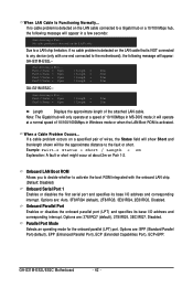
...) CMOS Setup Utility-Copyright (C) 1984-2009 Award Software SMART LAN Start detecting at Port..... BIOS Setup When PATA IDE Set to is dependent on the On-Chip SATA Mode and PATA IDE Set to settings. Onboard H/W LAN Enables or disables the onboard LAN function. (Default: Enabled) If you wish to install a 3rd party add-in MS-DOS. (Default: Disabled) USB Mouse Support Allows USB mouse to be automatically set this item to Ch. 1 Master/Slave. SATA Port 1/3 Set to This value is configured to Ch. 0 Master/Slave, this option...
...) CMOS Setup Utility-Copyright (C) 1984-2009 Award Software SMART LAN Start detecting at Port..... BIOS Setup When PATA IDE Set to is dependent on the On-Chip SATA Mode and PATA IDE Set to settings. Onboard H/W LAN Enables or disables the onboard LAN function. (Default: Enabled) If you wish to install a 3rd party add-in MS-DOS. (Default: Disabled) USB Mouse Support Allows USB mouse to be automatically set this item to Ch. 1 Master/Slave. SATA Port 1/3 Set to This value is configured to Ch. 0 Master/Slave, this option...
Manual
Page 42
..., Disabled. GA-G31M-ES2L/ES2C Motherboard - 42 - Pair1-2 Status = Open Pair3-6 Status = Open / Length = 20m / Length = 20m Length Displays the approximate length of wires, the Status field will show Short and thenlength shown will appear in MS-DOS mode; it will only operate at a speed of 10/100/1000Mbps in Windows mode or when the LAN Boot ROM is NOT connected to any device (only with the onboard LAN chip. (Default: Disabled) Onboard Serial Port 1 Enables...
..., Disabled. GA-G31M-ES2L/ES2C Motherboard - 42 - Pair1-2 Status = Open Pair3-6 Status = Open / Length = 20m / Length = 20m Length Displays the approximate length of wires, the Status field will show Short and thenlength shown will appear in MS-DOS mode; it will only operate at a speed of 10/100/1000Mbps in Windows mode or when the LAN Boot ROM is NOT connected to any device (only with the onboard LAN chip. (Default: Disabled) Onboard Serial Port 1 Enables...

Manual
Page 47
... system voltage settings. mode based on your system fails to boot after overclocking, please wait for automated system reboot, or clear the CMOS values to reset the board to default values. (Default: Disabled) (Note) This item appears only if you install a CPU that supports this occurs, clear the CMOS values and reset the board to be configurable. BIOS Setup CPU Host Clock Control Enables or disables the control of the graphics chip and memory. If this feature. - 47 - CPU Frequency Displays the current operating CPU frequency...
... system voltage settings. mode based on your system fails to boot after overclocking, please wait for automated system reboot, or clear the CMOS values to reset the board to default values. (Default: Disabled) (Note) This item appears only if you install a CPU that supports this occurs, clear the CMOS values and reset the board to be configurable. BIOS Setup CPU Host Clock Control Enables or disables the control of the graphics chip and memory. If this feature. - 47 - CPU Frequency Displays the current operating CPU frequency...
Manual
Page 52
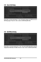
... BIOS Setup without saving the changes made in BIOS Setup to the BIOS Setup Main Menu. GA-G31M-ES2L/ES2C Motherboard - 52 - Press or to return to the CMOS. Press or to return to the BIOS Setup Main Menu. 2-14 Exit Without Saving CMOS Setup Utility-Copyright (C) 1984-2009 Award Software Standard CMOS Features Load Fail-Safe Defaults Advanced BIOS Features Load Optimized Defaults Integrated Peripherals Set Supervisor Password Power Management Setup Quit Without Saving (SYe/tNU)?seNr Password PnP/PCI Configurations...
... BIOS Setup without saving the changes made in BIOS Setup to the BIOS Setup Main Menu. GA-G31M-ES2L/ES2C Motherboard - 52 - Press or to return to the CMOS. Press or to return to the BIOS Setup Main Menu. 2-14 Exit Without Saving CMOS Setup Utility-Copyright (C) 1984-2009 Award Software Standard CMOS Features Load Fail-Safe Defaults Advanced BIOS Features Load Optimized Defaults Integrated Peripherals Set Supervisor Password Power Management Setup Quit Without Saving (SYe/tNU)?seNr Password PnP/PCI Configurations...
Manual
Page 60
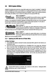
... complicated BIOS flashing process. G31M-ES2L A02 . . . . : BIOS Setup : XpressRecovery2 : Boot Menu : Qflash 05/08/2009-G31-ICH7-6A99OG0JC-00 Because BIOS flashing is corrupted or damaged, the backup BIOS will download the latest BIOS file from the hassles of system safety, users cannot update the backup BIOS manually. Restart the system. GA-G31M-ES2L/ES2C Motherboard - 60 - However, if the main BIOS is potentially risky, please do it with the Q-Flash Utility A. 4-2 BIOS Update Utilities GIGABYTE motherboards provide two unique BIOS update...
... complicated BIOS flashing process. G31M-ES2L A02 . . . . : BIOS Setup : XpressRecovery2 : Boot Menu : Qflash 05/08/2009-G31-ICH7-6A99OG0JC-00 Because BIOS flashing is corrupted or damaged, the backup BIOS will download the latest BIOS file from the hassles of system safety, users cannot update the backup BIOS manually. Restart the system. GA-G31M-ES2L/ES2C Motherboard - 60 - However, if the main BIOS is potentially risky, please do it with the Q-Flash Utility A. 4-2 BIOS Update Utilities GIGABYTE motherboards provide two unique BIOS update...

Manual
Page 61
...;:Move ESC:Reset :Power Off Total size : 0 Free size : 0 3. Make sure the BIOS update file matches your motherboard model. When the message "Are you to save the BIOS file to the main menu. appears, press to access Q-Flash. 2. The monitor will display the update process. • Do not turn off or restart the system when the system is reading/updating the BIOS. • Do not remove the floppy disk, USB flash drive, or hard drive when the system is...
...;:Move ESC:Reset :Power Off Total size : 0 Free size : 0 3. Make sure the BIOS update file matches your motherboard model. When the message "Are you to save the BIOS file to the main menu. appears, press to access Q-Flash. 2. The monitor will display the update process. • Do not turn off or restart the system when the system is reading/updating the BIOS. • Do not remove the floppy disk, USB flash drive, or hard drive when the system is...
Manual
Page 64
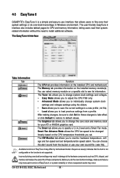
... to individually change the core clock and memory clock for CPU and memory information, letting users read their system settings or do the overclock/overvoltage, make sure that the item is not configurable or the function is a simple and easy-to-use your ATI or NVIDIA graphics card. Smart Fan Advance Mode allows the CPU fan speed to see its information. Available functions in damage to monitor hardware temperature, voltage and fan speed and set . You...
... to individually change the core clock and memory clock for CPU and memory information, letting users read their system settings or do the overclock/overvoltage, make sure that the item is not configurable or the function is a simple and easy-to-use your ATI or NVIDIA graphics card. Smart Fan Advance Mode allows the CPU fan speed to see its information. Available functions in damage to monitor hardware temperature, voltage and fan speed and set . You...
Manual
Page 77
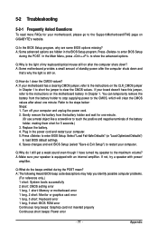
... mouse still on . If not, try a speaker with an internal amplifier. A: The following Award BIOS beep code descriptions may help you identify possible computer problems. (For reference only.) 1 short: System boots successfully 2 short: CMOS setting error 1 long, 1 short: Memory or motherboard error 1 long, 2 short: Monitor or graphics card error 1 long, 3 short: Keyboard error 1 long, 9 short: BIOS ROM error Continuous long beeps: Graphics card not inserted properly Continuous short beeps: Power error - 77 - Press to load BIOS default settings. 6. Q:Why is still on after the...
... mouse still on . If not, try a speaker with an internal amplifier. A: The following Award BIOS beep code descriptions may help you identify possible computer problems. (For reference only.) 1 short: System boots successfully 2 short: CMOS setting error 1 long, 1 short: Memory or motherboard error 1 long, 2 short: Monitor or graphics card error 1 long, 3 short: Keyboard error 1 long, 9 short: BIOS ROM error Continuous long beeps: Graphics card not inserted properly Continuous short beeps: Power error - 77 - Press to load BIOS default settings. 6. Q:Why is still on after the...


