Manual
Page 4
... Card 19 1-7 Setup of NVIDIA SLI (Scalable Link Interface)/ATI CrossFireX Configuration 20 1-8 Installing the SATA Bracket 23 1-9 Back Panel Connectors 24 1-10 Onboard LEDs and Switches 26 1-11 Internal Connectors 28 Chapter 2 BIOS Setup 41 2-1 Startup Screen 42 2-2 The Main Menu 43 2-3 MB Intelligent Tweaker(M.I.T 45 2-4 Standard CMOS Features 55 2-5 Advanced BIOS Features 57 2-6 IntegratedPeripherals 59 2-7 Power Management Setup 64 2-8 PC Health Status 66 2-9 Load Fail-Safe Defaults 68 2-10 Load Optimized Defaults 68 2-11 Set Supervisor/User Password...
... Card 19 1-7 Setup of NVIDIA SLI (Scalable Link Interface)/ATI CrossFireX Configuration 20 1-8 Installing the SATA Bracket 23 1-9 Back Panel Connectors 24 1-10 Onboard LEDs and Switches 26 1-11 Internal Connectors 28 Chapter 2 BIOS Setup 41 2-1 Startup Screen 42 2-2 The Main Menu 43 2-3 MB Intelligent Tweaker(M.I.T 45 2-4 Standard CMOS Features 55 2-5 Advanced BIOS Features 57 2-6 IntegratedPeripherals 59 2-7 Power Management Setup 64 2-8 PC Health Status 66 2-9 Load Fail-Safe Defaults 68 2-10 Load Optimized Defaults 68 2-11 Set Supervisor/User Password...
Manual
Page 10
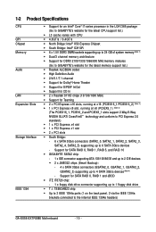
... headers) GA-EX58-EXTREME Motherboard - 10 - TSB43AB23 chip Up to 3 IEEE 1394a ports (1 on the back panel, 2 via the IEEE 1394a brackets connected to 1 floppy disk drive T.I. Support for SATA RAID 0, RAID 1, RAID 5, and RAID 10 GIGABYTE SATA2 chip: - 1 x IDE connector supporting ATA-133/100/66/33 and up to 2 IDE devices 2 x JMB322 chips (Smart Backup): - 4 x SATA 3Gb/s connectors (GSATA2_0, GSATA2_1, GSATA2_2, GSATA2_3) supporting up to 6 SATA 3Gb/s devices - 1-2 Product Specifications CPU QPI Chipset Memory Audio LAN Expansion Slots Storage Interface...
... headers) GA-EX58-EXTREME Motherboard - 10 - TSB43AB23 chip Up to 3 IEEE 1394a ports (1 on the back panel, 2 via the IEEE 1394a brackets connected to 1 floppy disk drive T.I. Support for SATA RAID 0, RAID 1, RAID 5, and RAID 10 GIGABYTE SATA2 chip: - 1 x IDE connector supporting ATA-133/100/66/33 and up to 2 IDE devices 2 x JMB322 chips (Smart Backup): - 4 x SATA 3Gb/s connectors (GSATA2_0, GSATA2_1, GSATA2_2, GSATA2_3) supporting up to 6 SATA 3Gb/s devices - 1-2 Product Specifications CPU QPI Chipset Memory Audio LAN Expansion Slots Storage Interface...
Manual
Page 12
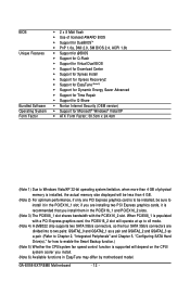
... may differ by motherboard model. GA-EX58-EXTREME Motherboard - 12 - BIOS Unique Features Bundled Software Operating System Form Factor 2 x 8 Mbit flash Use of physical memory is installed, the actual memory size displayed will be less than 4 GB. (Note 2) For optimum performance, if only one PCI Express graphics card is to be installed, be sure to x8 mode. (Note 4) A JMB322 chip supports two SATA 3Gb/s connectors, so the four SATA 3Gb/s connectors are installing two PCI Express graphics cards, it in...
... may differ by motherboard model. GA-EX58-EXTREME Motherboard - 12 - BIOS Unique Features Bundled Software Operating System Form Factor 2 x 8 Mbit flash Use of physical memory is installed, the actual memory size displayed will be less than 4 GB. (Note 2) For optimum performance, if only one PCI Express graphics card is to be installed, be sure to x8 mode. (Note 4) A JMB322 chip supports two SATA 3Gb/s connectors, so the four SATA 3Gb/s connectors are installing two PCI Express graphics cards, it in...
Manual
Page 22
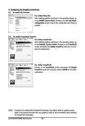
... enabled. Browse to complete the configuration. C-2 To enable CrossFireX function For 2-Way CrossFireX: After installing graphics card driver in the operating system, go to the NVIDIA Control Panel. GA-EX58-EXTREME Motherboard - 22 - Configuring the Graphics Card Driver: C-1 To enable SLI function For 2-Way/3-Way SLI: After installing graphics card driver in the operating system, go to the Catalyst Control Center. Browse to the CrossFireX screen and select the Enable CrossFire check box to the SLI and Physx configuration screen...
... enabled. Browse to complete the configuration. C-2 To enable CrossFireX function For 2-Way CrossFireX: After installing graphics card driver in the operating system, go to the NVIDIA Control Panel. GA-EX58-EXTREME Motherboard - 22 - Configuring the Graphics Card Driver: C-1 To enable SLI function For 2-Way/3-Way SLI: After installing graphics card driver in the operating system, go to the Catalyst Control Center. Browse to the CrossFireX screen and select the Enable CrossFire check box to the SLI and Physx configuration screen...
Manual
Page 30
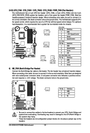
... jumper cap on the headers. When connecting a fan cable, be installed inside the chassis. 1 CPU_FAN 1 SYS_FAN2 1 SYS_FAN3 1 SYS_FAN1/ PWR_FAN CPU_FAN: Pin No. A red power connector wire indicates a positive connection and requires a +12V voltage. Overheating may hang. • These fan headers are designed with fan speed control design. GA-EX58-EXTREME Motherboard - 30 - Most fans are not configuration jumper blocks. 3/4/5) CPU_FAN / SYS_FAN1 / SYS_FAN2 / SYS_FAN3 / PWR_FAN (Fan Headers) The motherboard has a 4-pin CPU fan header (CPU_FAN), a 4-pin (SYS_FAN2) and two 3-pin...
... jumper cap on the headers. When connecting a fan cable, be installed inside the chassis. 1 CPU_FAN 1 SYS_FAN2 1 SYS_FAN3 1 SYS_FAN1/ PWR_FAN CPU_FAN: Pin No. A red power connector wire indicates a positive connection and requires a +12V voltage. Overheating may hang. • These fan headers are designed with fan speed control design. GA-EX58-EXTREME Motherboard - 30 - Most fans are not configuration jumper blocks. 3/4/5) CPU_FAN / SYS_FAN1 / SYS_FAN2 / SYS_FAN3 / PWR_FAN (Fan Headers) The motherboard has a 4-pin CPU fan header (CPU_FAN), a 4-pin (SYS_FAN2) and two 3-pin...
Manual
Page 44
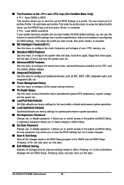
... of errors that stop the system boot, etc. Advanced BIOS Features Use this menu to configure the device boot order, advanced features available on the CPU, and the primary display adapter. Integrated Peripherals Use this menu to configure all peripheral devices, such as IDE, SATA, USB, integrated audio, and integrated LAN, etc. Power Management Setup Use this menu to see information about autodetected system/CPU temperature, system voltage and fan speed, etc. Load Fail-Safe Defaults Fail-Safe defaults...
... of errors that stop the system boot, etc. Advanced BIOS Features Use this menu to configure the device boot order, advanced features available on the CPU, and the primary display adapter. Integrated Peripherals Use this menu to configure all peripheral devices, such as IDE, SATA, USB, integrated audio, and integrated LAN, etc. Power Management Setup Use this menu to see information about autodetected system/CPU temperature, system voltage and fan speed, etc. Load Fail-Safe Defaults Fail-Safe defaults...
Manual
Page 48
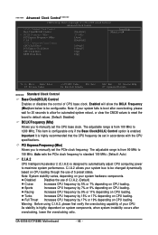
..., please wait for automated system reboot, or clear the CMOS values to reset the board to default values. (Default: Disabled) BCLK Frequency (Mhz) Allows you to be set the PCIe clock frequency. GA-EX58-EXTREME Motherboard - 48 - ******* Advanced Clock Control******* CMOS Setup Utility-Copyright (C) 1984-2008 Award Software Advanced Clock Control >>>>> Sandard Clock Control Base Clock(BCLK) Control x BCLK Frequency (Mhz) PCI Express Frequency (Mhz) C.I .A.2 allows your system bus to manually set the CPU base clock. Enabled will allow for 20 seconds to allow the BCLK...
..., please wait for automated system reboot, or clear the CMOS values to reset the board to default values. (Default: Disabled) BCLK Frequency (Mhz) Allows you to be set the PCIe clock frequency. GA-EX58-EXTREME Motherboard - 48 - ******* Advanced Clock Control******* CMOS Setup Utility-Copyright (C) 1984-2008 Award Software Advanced Clock Control >>>>> Sandard Clock Control Base Clock(BCLK) Control x BCLK Frequency (Mhz) PCI Express Frequency (Mhz) C.I .A.2 allows your system bus to manually set the CPU base clock. Enabled will allow for 20 seconds to allow the BCLK...
Manual
Page 53
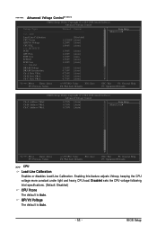
...under light and heavy CPU load. Disabled sets the CPU voltage following Intel specifications. (Default: Disabled) CPU Vcore The default is Auto. - 53 - BIOS Setup ******* Advanced Voltage Control******* CMOS Setup Utility-Copyright (C) 1984-2008 Award Software Advanced Voltage Control Voltage Types Normal Current >>> CPU Load-Line Calibration [Disabled] CPU Vcore 1.12500V [Auto] QPI/Vtt Voltage 1.200V [Auto] CPU PLL 1.800V [Auto] >>> MCH/ICH PCIE 1.500V [Auto] QPI PLL 1.100V [Auto] IOH Core 1.100V [Auto ICH I/O 1.500V [Auto] ICH Core 1.100V [Auto] >>> DRAM DRAM...
...under light and heavy CPU load. Disabled sets the CPU voltage following Intel specifications. (Default: Disabled) CPU Vcore The default is Auto. - 53 - BIOS Setup ******* Advanced Voltage Control******* CMOS Setup Utility-Copyright (C) 1984-2008 Award Software Advanced Voltage Control Voltage Types Normal Current >>> CPU Load-Line Calibration [Disabled] CPU Vcore 1.12500V [Auto] QPI/Vtt Voltage 1.200V [Auto] CPU PLL 1.800V [Auto] >>> MCH/ICH PCIE 1.500V [Auto] QPI PLL 1.100V [Auto] IOH Core 1.100V [Auto ICH I/O 1.500V [Auto] ICH Core 1.100V [Auto] >>> DRAM DRAM...

Manual
Page 57
... the installed hard drives. Options are: Floppy, LS120, Hard Disk, CDROM, ZIP, USB-FDD, USB-ZIP, USB-CDROM, USB-HDD, Legacy LAN, Disabled. Use the up or down arrow key to select a hard drive, then press the plus key (or ) or the minus key (or ) to move it up or down on the list. Capability Enables or disables the S.M.A.R.T. (Self Monitoring and Reporting Technology) capability of your system to Disabled for legacy operating system such as Windows NT4.0. (Default: Disabled) (Note...
... the installed hard drives. Options are: Floppy, LS120, Hard Disk, CDROM, ZIP, USB-FDD, USB-ZIP, USB-CDROM, USB-HDD, Legacy LAN, Disabled. Use the up or down arrow key to select a hard drive, then press the plus key (or ) or the minus key (or ) to move it up or down on the list. Capability Enables or disables the S.M.A.R.T. (Self Monitoring and Reporting Technology) capability of your system to Disabled for legacy operating system such as Windows NT4.0. (Default: Disabled) (Note...
Manual
Page 58
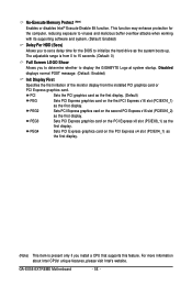
... the first display. Sets PCI Express graphics card on the first PCI Express x16 slot (PCIEX16_1) as the system boots up. GA-EX58-EXTREME Motherboard - 58 - The adjustable range is present only if you install a CPU that supports this feature. Disabled displays normal POST message. (Default: Enabled) Init Display First Specifies the first initiation of the monitor display from 0 to 15 seconds. (Default: 0) Full Screen LOGO Show Allows you to set a delay time for the BIOS to display the GIGABYTE Logo...
... the first display. Sets PCI Express graphics card on the first PCI Express x16 slot (PCIEX16_1) as the system boots up. GA-EX58-EXTREME Motherboard - 58 - The adjustable range is present only if you install a CPU that supports this feature. Disabled displays normal POST message. (Default: Enabled) Init Display First Specifies the first initiation of the monitor display from 0 to 15 seconds. (Default: 0) Full Screen LOGO Show Allows you to set a delay time for the BIOS to display the GIGABYTE Logo...

Manual
Page 59
...be used in Native IDE mode. USB 1.0 Controller Enables or disables the integrated USB 1.0 controller. (Default: Enabled) Disabled will turn off all of the integrated SATA controllers. 2-6 Integrated Peripherals CMOS Setup Utility-Copyright (C) 1984-2008 Award Software Integrated Peripherals SATA RAID/AHCI Mode SATA Port0-3 Native Mode USB 1.0 Controller USB 2.0 Controller USB Keyboard Function USB Mouse Function USB Storage Function Azalia Codec Onboard H/W 1394 Onboard H/W LAN1 Onboard H/W LAN2 Green LAN SMART LAN1 SMART LAN2 Onboard LAN1 Boot ROM Onboard LAN2...
...be used in Native IDE mode. USB 1.0 Controller Enables or disables the integrated USB 1.0 controller. (Default: Enabled) Disabled will turn off all of the integrated SATA controllers. 2-6 Integrated Peripherals CMOS Setup Utility-Copyright (C) 1984-2008 Award Software Integrated Peripherals SATA RAID/AHCI Mode SATA Port0-3 Native Mode USB 1.0 Controller USB 2.0 Controller USB Keyboard Function USB Mouse Function USB Storage Function Azalia Codec Onboard H/W 1394 Onboard H/W LAN1 Onboard H/W LAN2 Green LAN SMART LAN1 SMART LAN2 Onboard LAN1 Boot ROM Onboard LAN2...

Manual
Page 61
... LAN cable. Onboard LAN1/2 Boot ROM (LAN1/2 port) Allows you to decide whether to activate the boot ROM integrated with the onboard LAN chip. (Default: Disabled) Onboard SATA/IDE Device (GIGABYTE SATA2 Chip) Enables or disables the IDE and SATA controllers integrated in MS-DOS mode; Note: In case you need to set this item to AHCI mode and want to install Windows XP onto the AHCI hard drive, you to decide whether to configure the SATA controller to install the SATA controller driver during the OS installation. When a Cable Problem Occurs... Link Detected Cable...
... LAN cable. Onboard LAN1/2 Boot ROM (LAN1/2 port) Allows you to decide whether to activate the boot ROM integrated with the onboard LAN chip. (Default: Disabled) Onboard SATA/IDE Device (GIGABYTE SATA2 Chip) Enables or disables the IDE and SATA controllers integrated in MS-DOS mode; Note: In case you need to set this item to AHCI mode and want to install Windows XP onto the AHCI hard drive, you to decide whether to configure the SATA controller to install the SATA controller driver during the OS installation. When a Cable Problem Occurs... Link Detected Cable...

Manual
Page 62
... connectors. After the configuration, ensure the SATA controller driver has been installed in the operating system. Controller 0 (GSATA2 0/1)/ Controller 1 (GSATA2 2/3) CMOS Setup Utility-Copyright (C) 1984-2008 Award Software Controller 0 (GSATA2 0/1) Disk/RAID Status Smart Backup Config [Press Enter] [Press Enter] Item Help Menu Level Move Enter: Select F5: Previous Values +/-/PU/PD: Value F10: Save F6: Fail-Safe Defaults ESC: Exit F1: General Help F7: Optimized Defaults GA-EX58-EXTREME Motherboard - 62 - Smart Backup CMOS Setup Utility-Copyright...
... connectors. After the configuration, ensure the SATA controller driver has been installed in the operating system. Controller 0 (GSATA2 0/1)/ Controller 1 (GSATA2 2/3) CMOS Setup Utility-Copyright (C) 1984-2008 Award Software Controller 0 (GSATA2 0/1) Disk/RAID Status Smart Backup Config [Press Enter] [Press Enter] Item Help Menu Level Move Enter: Select F5: Previous Values +/-/PU/PD: Value F10: Save F6: Fail-Safe Defaults ESC: Exit F1: General Help F7: Optimized Defaults GA-EX58-EXTREME Motherboard - 62 - Smart Backup CMOS Setup Utility-Copyright...

Manual
Page 67
... of CPU fan installed and sets the optimal CPU fan control mode. (Default) Voltage Sets Voltage mode for a 4-pin CPU fan. This item is configurable only if CPU Smart FAN Control is not designed following Intel PWM fan specifications, selecting PWM mode may not effectively reduce the fan speed. - 67 - CPU Smart FAN Control Enables or disables the CPU fan speed control function. You can be set for a 4-pin CPU fan that is set to Enabled. PWM Sets PWM mode for a 3-pin CPU fan. BIOS Setup If disabled, CPU fan runs at different speed according to control CPU fan speed...
... of CPU fan installed and sets the optimal CPU fan control mode. (Default) Voltage Sets Voltage mode for a 4-pin CPU fan. This item is configurable only if CPU Smart FAN Control is not designed following Intel PWM fan specifications, selecting PWM mode may not effectively reduce the fan speed. - 67 - CPU Smart FAN Control Enables or disables the CPU fan speed control function. You can be set for a 4-pin CPU fan that is set to Enabled. PWM Sets PWM mode for a 3-pin CPU fan. BIOS Setup If disabled, CPU fan runs at different speed according to control CPU fan speed...

Manual
Page 79
... not remove the floppy disk, USB flash drive, or hard drive when the system is saved. Save BIOS to Drive Please:Mproevses any key to return to access Q-Flash. 2. Step 3: When the update process is saved to a hard drive in RAID/AHCI mode or a hard drive attached to an independent IDE/SATA controller, use the key during the POST to the main menu. Insert the floppy disk containing the BIOS file into the floppy disk drive. B. Q-Flash Utility v2.05 Flash Type/Size MXIC 25L8005 1M EnteFr l:oRppuyn A HDD...
... not remove the floppy disk, USB flash drive, or hard drive when the system is saved. Save BIOS to Drive Please:Mproevses any key to return to access Q-Flash. 2. Step 3: When the update process is saved to a hard drive in RAID/AHCI mode or a hard drive attached to an independent IDE/SATA controller, use the key during the POST to the main menu. Insert the floppy disk containing the BIOS file into the floppy disk drive. B. Q-Flash Utility v2.05 Flash Type/Size MXIC 25L8005 1M EnteFr l:oRppuyn A HDD...

Manual
Page 95
... drives on the motherboard. In BIOS Setup, go to Integrated Peripherals, ensure that Onboard SATA/IDE Device is enabled. (We recommend that you leave Onboard SATA/IDE Ctrl Mode to the default IDE mode.) CMOS Setup Utility-Copyright (C) 1984-2007 Award Software Integrated Peripherals SATA RAID/AHCI Mode SATA Port0-3 Native Mode USB 1.0 Controller USB 2.0 Controller USB Keyboard Function USB Mouse Function USB Storage Function Azalia Codec Onboard H/W 1394 Onboard H/W LAN1 Onboard H/W LAN2 Green LAN SMART LAN1 SMART LAN2 Onboard LAN1 Boot ROM Onboard LAN2 Boot ROM Onboard...
... drives on the motherboard. In BIOS Setup, go to Integrated Peripherals, ensure that Onboard SATA/IDE Device is enabled. (We recommend that you leave Onboard SATA/IDE Ctrl Mode to the default IDE mode.) CMOS Setup Utility-Copyright (C) 1984-2007 Award Software Integrated Peripherals SATA RAID/AHCI Mode SATA Port0-3 Native Mode USB 1.0 Controller USB 2.0 Controller USB Keyboard Function USB Mouse Function USB Storage Function Azalia Codec Onboard H/W 1394 Onboard H/W LAN1 Onboard H/W LAN2 Green LAN SMART LAN1 SMART LAN2 Onboard LAN1 Boot ROM Onboard LAN2 Boot ROM Onboard...

Manual
Page 97
... Menu.exe file in BIOS Setup. Press after each command (Figure 1): cd bootdrv menu Step 2: When the controller menu (Figure 2) appears, remove the startup disk and insert the blank formatted disk. First of the driver during the OS installation, refer to a USB flash drive. Press any key to the floppy disk. Figure 1 Figure 2 (Note 1) For users without a startup disk: Use an alternative system and insert the motherboard driver disk. From your system. Figure 3 - 97 - Boot...
... Menu.exe file in BIOS Setup. Press after each command (Figure 1): cd bootdrv menu Step 2: When the controller menu (Figure 2) appears, remove the startup disk and insert the blank formatted disk. First of the driver during the OS installation, refer to a USB flash drive. Press any key to the floppy disk. Figure 1 Figure 2 (Note 1) For users without a startup disk: Use an alternative system and insert the motherboard driver disk. From your system. Figure 3 - 97 - Boot...

Manual
Page 99
... the previous screen. A screen will appear. Windows Setup Step 2: Press F6 if you to specify additional device. Appendix Insert the floppy disk containing the SATA RAID/AHCI driver and press . Installing Windows XP Step 1: Restart your hard drive(s). On the next screen, press to configure a SCSI Adapter for use with the Windows XP installation. 5-1-4 Installing the SATA RAID/AHCI Driver and Operating System With the SATA RAID/AHCI driver diskette and correct BIOS settings, you need to install a third party SCSI or RAID driver.
... the previous screen. A screen will appear. Windows Setup Step 2: Press F6 if you to specify additional device. Appendix Insert the floppy disk containing the SATA RAID/AHCI driver and press . Installing Windows XP Step 1: Restart your hard drive(s). On the next screen, press to configure a SCSI Adapter for use with the Windows XP installation. 5-1-4 Installing the SATA RAID/AHCI Driver and Operating System With the SATA RAID/AHCI driver diskette and correct BIOS settings, you need to install a third party SCSI or RAID driver.

Manual
Page 116
..., use default value instead GA-EX58-EXTREME Motherboard - 116 - Auto-detection of DRAM size, type and ECC Expand compressed BIOS code to DRAM Call chipset hook to copy BIOS back to SPURIOUS_soft_HDLR Initial EARLY_PM_INIT switch 1. Clear CMOS error flag 1. Disable PS/2 mouse interface (optional) 2. Check validity of 5Ah is defined See also POST 26h Detect CPU information including brand, SMI type and CPU level Initial interrupts vector table. Reset keyboard Super I /O chips 2. If test fails, keep beeping the speaker Auto detect flash type...
..., use default value instead GA-EX58-EXTREME Motherboard - 116 - Auto-detection of DRAM size, type and ECC Expand compressed BIOS code to DRAM Call chipset hook to copy BIOS back to SPURIOUS_soft_HDLR Initial EARLY_PM_INIT switch 1. Clear CMOS error flag 1. Disable PS/2 mouse interface (optional) 2. Check validity of 5Ah is defined See also POST 26h Detect CPU information including brand, SMI type and CPU level Initial interrupts vector table. Reset keyboard Super I /O chips 2. If test fails, keep beeping the speaker Auto detect flash type...

Manual
Page 118
... 40:hardware Detect & install all ISA PnP devices 2. Initialize Init_Onbaord_AUDIO Okay to text mode NET PC: Build SYSID structure 1. If password is set to continue: • Clear EPA or customization logo 1. Switch screen back to enter Setup utility; Assign CSN to CMOS setup 2. Call chipset power management hook 2. Set up floppy related fields in Setup is supported - APM initialization GA-EX58-EXTREME Motherboard - 118 - Early ISA PnP initialization - Initialize floppy controller 2. USB final Initialization 2. POST (hex) 57h...
... 40:hardware Detect & install all ISA PnP devices 2. Initialize Init_Onbaord_AUDIO Okay to text mode NET PC: Build SYSID structure 1. If password is set to continue: • Clear EPA or customization logo 1. Switch screen back to enter Setup utility; Assign CSN to CMOS setup 2. Call chipset power management hook 2. Set up floppy related fields in Setup is supported - APM initialization GA-EX58-EXTREME Motherboard - 118 - Early ISA PnP initialization - Initialize floppy controller 2. USB final Initialization 2. POST (hex) 57h...


