Manual
Page 4
... Contents Box Contents ...6 OptionalItems...6 GA-EP43C-DS3 Motherboard Layout 7 Block Diagram...8 Chapter 1 Hardware Installation 9 1-1 Installation Precautions 9 1-2 Product Specifications 10 1-3 Installing the CPU and CPU Cooler 13 1-3-1 Installing the CPU 13 1-3-2 Installing the CPU Cooler 15 1-4 Installing the Memory 16 1-4-1 Dual Channel Memory Configuration 16 1-4-2 Installing a Memory 17 1-5 Installing an Expansion Card 18 1-6 Back Panel Connectors 19 1-7 Internal Connectors 21 Chapter 2 BIOS Setup 33 2-1 Startup Screen 34 2-2 The Main Menu 35 2-3 MB Intelligent Tweaker...
... Contents Box Contents ...6 OptionalItems...6 GA-EP43C-DS3 Motherboard Layout 7 Block Diagram...8 Chapter 1 Hardware Installation 9 1-1 Installation Precautions 9 1-2 Product Specifications 10 1-3 Installing the CPU and CPU Cooler 13 1-3-1 Installing the CPU 13 1-3-2 Installing the CPU Cooler 15 1-4 Installing the Memory 16 1-4-1 Dual Channel Memory Configuration 16 1-4-2 Installing a Memory 17 1-5 Installing an Expansion Card 18 1-6 Back Panel Connectors 19 1-7 Internal Connectors 21 Chapter 2 BIOS Setup 33 2-1 Startup Screen 34 2-2 The Main Menu 35 2-3 MB Intelligent Tweaker...
Manual
Page 10
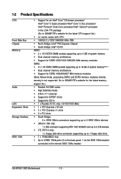
... latest memory support list.) Š Realtek ALC888 codec Š High Definition Audio Š 2/4/5.1/7.1-channel Š Support for S/PDIF In/Out Š Support for CD In Š 1 x Realtek 8111C chip (10/100/1000 Mbit) Š 1 x PCI Express x16 slot Š 3 x PCI Express x1 slots Š 3 x PCI slots Š South Bridge: - 6 x SATA 3Gb/s connectors supporting up to 6 SATA 3Gb/s devices Š JMicron 368 chip: - 1 x IDE connector supporting ATA-133/100/66/33 and up to 2 IDE devices Š iTE IT8718 chip: - 1 x floppy disk drive connector supporting...
... latest memory support list.) Š Realtek ALC888 codec Š High Definition Audio Š 2/4/5.1/7.1-channel Š Support for S/PDIF In/Out Š Support for CD In Š 1 x Realtek 8111C chip (10/100/1000 Mbit) Š 1 x PCI Express x16 slot Š 3 x PCI Express x1 slots Š 3 x PCI slots Š South Bridge: - 6 x SATA 3Gb/s connectors supporting up to 6 SATA 3Gb/s devices Š JMicron 368 chip: - 1 x IDE connector supporting ATA-133/100/66/33 and up to 2 IDE devices Š iTE IT8718 chip: - 1 x floppy disk drive connector supporting...
Manual
Page 16
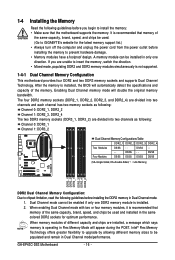
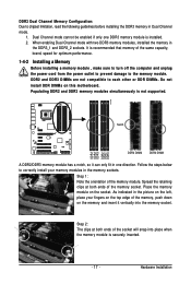
... : Channel 0: DDR2_1, DDR2_2 Channel 1: DDR2_3, DDR2_4 The two DDR3 memory sockets (DDR3_1, DDR3_2) are unable to install the memory: • Make sure that the motherboard supports the memory. When enabling Dual Channel mode with two or four memory modules, it is installed. 2. After the memory is not supported. 1-4-1 Dual Channel Memory Configuration This motherboard provides four DDR2 and two DDR3 memory sockets and supports Dual Channel Technology. Intel® Flex Memory Technology offers greater flexibility to upgrade by allowing different memory sizes to GIGABYTE...
... : Channel 0: DDR2_1, DDR2_2 Channel 1: DDR2_3, DDR2_4 The two DDR3 memory sockets (DDR3_1, DDR3_2) are unable to install the memory: • Make sure that the motherboard supports the memory. When enabling Dual Channel mode with two or four memory modules, it is installed. 2. After the memory is not supported. 1-4-1 Dual Channel Memory Configuration This motherboard provides four DDR2 and two DDR3 memory sockets and supports Dual Channel Technology. Intel® Flex Memory Technology offers greater flexibility to upgrade by allowing different memory sizes to GIGABYTE...
Manual
Page 17
... in one DDR3 memory module is recommended that memory of the same capacity, brand, speed for optimum performance. 1-4-2 Installing a Memory Before installing a memory module , make sure to turn off the computer and unplug the power cord from the power outlet to prevent damage to each other or DDR DIMMs. Do not install DDR DIMMs on the socket. Dual Channel mode cannot be enabled if only one...
... in one DDR3 memory module is recommended that memory of the same capacity, brand, speed for optimum performance. 1-4-2 Installing a Memory Before installing a memory module , make sure to turn off the computer and unplug the power cord from the power outlet to prevent damage to each other or DDR DIMMs. Do not install DDR DIMMs on the socket. Dual Channel mode cannot be enabled if only one...
Manual
Page 18
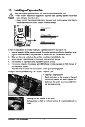
... expansion slot. 1. Install the driver provided with a screw. 5. GA-EP43C-DS3 Motherboard - 18 - Make sure the card is fully inserted into the slot. 4. PCI Express x1 Slot PCI Express x16 Slot PCI Slot Follow the steps below to make any required BIOS changes for your card. Carefully read the manual that supports your expansion card(s). 7. Align the card with your computer. Example: Installing and Removing a PCI Express Graphics Card: • Installing a Graphics Card: Gently push down on the card are completely inserted into the PCI Express slot...
... expansion slot. 1. Install the driver provided with a screw. 5. GA-EP43C-DS3 Motherboard - 18 - Make sure the card is fully inserted into the slot. 4. PCI Express x1 Slot PCI Express x16 Slot PCI Slot Follow the steps below to make any required BIOS changes for your card. Carefully read the manual that supports your expansion card(s). 7. Align the card with your computer. Example: Installing and Removing a PCI Express Graphics Card: • Installing a Graphics Card: Gently push down on the card are completely inserted into the PCI Express slot...
Manual
Page 22
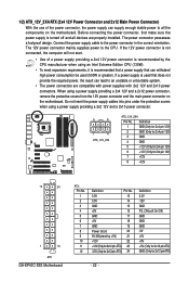
... main power connector on the motherboard. If a power supply is used (500W or greater). Connect the power supply cable to the CPU. The 12V power connector mainly supplies power to the power connector in the correct orientation. Definition 1 GND (Only for 2x4 pin 12V) 2 GND (Only for 2x4 pin 12V) 3 GND 4 GND 5 +12V (Only for 2x4 pin 12V) 6 +12V (Only for 2x12 pin ATX) - 22 - If the 12V power connector is not connected, the computer will not start...
... main power connector on the motherboard. If a power supply is used (500W or greater). Connect the power supply cable to the CPU. The 12V power connector mainly supplies power to the power connector in the correct orientation. Definition 1 GND (Only for 2x4 pin 12V) 2 GND (Only for 2x4 pin 12V) 3 GND 4 GND 5 +12V (Only for 2x4 pin 12V) 6 +12V (Only for 2x12 pin ATX) - 22 - If the 12V power connector is not connected, the computer will not start...
Manual
Page 23
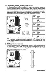
...6) FDD (Floppy Disk Drive Connector) This connector is recommended that a system fan be sure to locate pin 1 of floppy disk drives supported are not configuration jumper blocks. Definition 1 GND 2 +12V 3 Sense • Be sure to connect fan cables to the fan headers to connect a floppy disk drive. 3/4/5) CPU_FAN/SYS_FAN1/SYS_FAN2/PWR_FAN (Fan Headers) The motherboard has a 4-pin CPU fan header (CPU_FAN), a 3-pin (SYS_FAN1) and a 4-pin (SYS_FAN2) system fan headers, and a 3-pin power fan header (PWR_FAN). The motherboard supports CPU fan speed control, which requires the use of...
...6) FDD (Floppy Disk Drive Connector) This connector is recommended that a system fan be sure to locate pin 1 of floppy disk drives supported are not configuration jumper blocks. Definition 1 GND 2 +12V 3 Sense • Be sure to connect fan cables to the fan headers to connect a floppy disk drive. 3/4/5) CPU_FAN/SYS_FAN1/SYS_FAN2/PWR_FAN (Fan Headers) The motherboard has a 4-pin CPU fan header (CPU_FAN), a 3-pin (SYS_FAN1) and a 4-pin (SYS_FAN2) system fan headers, and a 3-pin power fan header (PWR_FAN). The motherboard supports CPU fan speed control, which requires the use of...

Manual
Page 31
... (Chassis Intrusion Header) This motherboard provides a chassis detection feature that detects if the chassis cover has been removed. Pin No. To clear the CMOS values, place a jumper cap on your computer, be sure to touch the two pins for BIOS configurations). - 31 - Hardware Installation date information and BIOS configurations) and reset the CMOS values to clear the CMOS values (e.g. Open: Normal Short: Clear CMOS Values • Always turn off your computer and unplug the power...
... (Chassis Intrusion Header) This motherboard provides a chassis detection feature that detects if the chassis cover has been removed. Pin No. To clear the CMOS values, place a jumper cap on your computer, be sure to touch the two pins for BIOS configurations). - 31 - Hardware Installation date information and BIOS configurations) and reset the CMOS values to clear the CMOS values (e.g. Open: Normal Short: Clear CMOS Values • Always turn off your computer and unplug the power...

Manual
Page 36
... CPU, memory, etc. „ Standard CMOS Features Use this menu to configure the system time and date, hard drive types, floppy disk drive types, and the type of errors that stop the system boot, etc. „ Advanced BIOS Features Use this menu to configure the device boot order, advanced features available on the CPU, and the primary display adapter. „ Integrated Peripherals Use this menu to configure all peripheral devices, such as IDE, SATA, USB, integrated audio, and integrated LAN, etc. „ Power Management Setup Use...
... CPU, memory, etc. „ Standard CMOS Features Use this menu to configure the system time and date, hard drive types, floppy disk drive types, and the type of errors that stop the system boot, etc. „ Advanced BIOS Features Use this menu to configure the device boot order, advanced features available on the CPU, and the primary display adapter. „ Integrated Peripherals Use this menu to configure all peripheral devices, such as IDE, SATA, USB, integrated audio, and integrated LAN, etc. „ Power Management Setup Use...

Manual
Page 38
...CPU clock ratio set the R.G.B. Enabled will work stably with unlocked clock ratio is installed. GA-EP43C-DS3 Motherboard - 38 - Auto allows the BIOS to CPU, chipset, or memory and reduce the useful life of CPU host clock. Options are: Auto (default), Fast, Turbo. CMOS Setup Utility-Copyright (C) 1984-2008 Award Software MB Intelligent Tweaker(M.I.T.) MCH Core MCH Reference MCH/DRAM Reference ICH I/O >>> DRAM DRAM Voltage DRAM Termination Channel A Reference Channel B Reference 1.100V 0.760V 0.900V 1.500V [Auto] [Auto] [Auto] [Auto] 1.800V 0.900V 0.900V 0.900V [Auto] [Auto] [Auto...
...CPU clock ratio set the R.G.B. Enabled will work stably with unlocked clock ratio is installed. GA-EP43C-DS3 Motherboard - 38 - Auto allows the BIOS to CPU, chipset, or memory and reduce the useful life of CPU host clock. Options are: Auto (default), Fast, Turbo. CMOS Setup Utility-Copyright (C) 1984-2008 Award Software MB Intelligent Tweaker(M.I.T.) MCH Core MCH Reference MCH/DRAM Reference ICH I/O >>> DRAM DRAM Voltage DRAM Termination Channel A Reference Channel B Reference 1.100V 0.760V 0.900V 1.500V [Auto] [Auto] [Auto] [Auto] 1.800V 0.900V 0.900V 0.900V [Auto] [Auto] [Auto...

Manual
Page 47
... ) or the minus key (or ) to move it up or down on the list. Options are: Floppy, LS120, Hard Disk, CDROM, ZIP, USB-FDD, USB-ZIP, USB-CDROM, USB-HDD, Legacy LAN, Disabled. HDD S.M.A.R.T. 2-5 Advanced BIOS Features CMOS Setup Utility-Copyright (C) 1984-2008 Award Software Advanced BIOS Features ` Hard Disk Boot Priority First Boot Device Second Boot Device Third Boot Device Password Check HDD S.M.A.R.T. Capability Enables or disables the S.M.A.R.T. (Self Monitoring and Reporting Technology) capability of your system to report read/write errors of loading the operating system from...
... ) or the minus key (or ) to move it up or down on the list. Options are: Floppy, LS120, Hard Disk, CDROM, ZIP, USB-FDD, USB-ZIP, USB-CDROM, USB-HDD, Legacy LAN, Disabled. HDD S.M.A.R.T. 2-5 Advanced BIOS Features CMOS Setup Utility-Copyright (C) 1984-2008 Award Software Advanced BIOS Features ` Hard Disk Boot Priority First Boot Device Second Boot Device Third Boot Device Password Check HDD S.M.A.R.T. Capability Enables or disables the S.M.A.R.T. (Self Monitoring and Reporting Technology) capability of your system to report read/write errors of loading the operating system from...

Manual
Page 50
...(Default: Enabled) GA-EP43C-DS3 Motherboard - 50 - In Legacy mode the SATA controllers use dedicated IRQs that support Native mode. Enable Native IDE mode if you wish to install operating Enabled systems that allows the storage driver to AHCI mode. 2-6 Integrated Peripherals CMOS Setup Utility-Copyright (C) 1984-2008 Award Software Integrated Peripherals SATA AHCI Mode SATA Port0-3 Native Mode USB Controller USB 2.0 Controller USB Keyboard Support USB Mouse Support Legacy USB storage detect Azalia Codec Onboard H/W 1394 Onboard H/W LAN Green LAN ` SMART LAN Onboard LAN Boot ROM...
...(Default: Enabled) GA-EP43C-DS3 Motherboard - 50 - In Legacy mode the SATA controllers use dedicated IRQs that support Native mode. Enable Native IDE mode if you wish to install operating Enabled systems that allows the storage driver to AHCI mode. 2-6 Integrated Peripherals CMOS Setup Utility-Copyright (C) 1984-2008 Award Software Integrated Peripherals SATA AHCI Mode SATA Port0-3 Native Mode USB Controller USB 2.0 Controller USB Keyboard Support USB Mouse Support Legacy USB storage detect Azalia Codec Onboard H/W 1394 Onboard H/W LAN Green LAN ` SMART LAN Onboard LAN Boot ROM...
Manual
Page 51
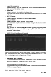
...51 - Legacy USB storage detect Determines whether to detect USB storage devices, including USB flash drives and USB hard drives during the POST. (Default: Enabled) Azalia Codec Enables or disables the onboard audio function. (Default: Auto) If you wish to install a 3rd party add-in network card instead of using the onboard audio, set this item to Disabled. If not, the corresponding LAN controller will be disabled automatically. (Default: Disabled) SMART LAN (LAN Cable Diagnostic Function) CMOS Setup Utility-Copyright (C) 1984-2008 Award Software SMART LAN Start detecting at Port.....
...51 - Legacy USB storage detect Determines whether to detect USB storage devices, including USB flash drives and USB hard drives during the POST. (Default: Enabled) Azalia Codec Enables or disables the onboard audio function. (Default: Auto) If you wish to install a 3rd party add-in network card instead of using the onboard audio, set this item to Disabled. If not, the corresponding LAN controller will be disabled automatically. (Default: Disabled) SMART LAN (LAN Cable Diagnostic Function) CMOS Setup Utility-Copyright (C) 1984-2008 Award Software SMART LAN Start detecting at Port.....
Manual
Page 52
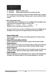
... pair of 10/100/1000 Mbps in Windows mode or when the LAN Boot ROM is the approximate length of 10/100 Mbps in MS-DOS mode; Link Detected --> 100Mbps Cable Length= 30m Link Detected Cable Length Displays transmission speed Displays the approximate length of the attached LAN cable. Onboard Parallel Port Enables or disables the onboard parallel port (LPT) and specifies its base I /O address and corresponding interrupt. GA-EP43C-DS3 Motherboard - 52 -
... pair of 10/100/1000 Mbps in Windows mode or when the LAN Boot ROM is the approximate length of 10/100 Mbps in MS-DOS mode; Link Detected --> 100Mbps Cable Length= 30m Link Detected Cable Length Displays transmission speed Displays the approximate length of the attached LAN cable. Onboard Parallel Port Enables or disables the onboard parallel port (LPT) and specifies its base I /O address and corresponding interrupt. GA-EP43C-DS3 Motherboard - 52 -

Manual
Page 56
CPU Warning Temperature Sets the warning threshold for CPU temperature. When CPU temperature exceeds the threshold, BIOS will emit warning sound. CPU/SYSTEM/POWER FAN Fail Warning Allows the system to emit warning sound if the CPU/system/power fan is removed, this occurs. (Default: Disabled) GA-EP43C-DS3 Motherboard - 56 - To clear the chassis intrusion status record, set Reset Case Open Status to Enabled, save the settings to the motherboard CI header. Current System/CPU Temperature Displays current system/CPU temperature. Options are: Disabled (default), 60oC/140oF, 70oC/158oF, ...
CPU Warning Temperature Sets the warning threshold for CPU temperature. When CPU temperature exceeds the threshold, BIOS will emit warning sound. CPU/SYSTEM/POWER FAN Fail Warning Allows the system to emit warning sound if the CPU/system/power fan is removed, this occurs. (Default: Disabled) GA-EP43C-DS3 Motherboard - 56 - To clear the chassis intrusion status record, set Reset Case Open Status to Enabled, save the settings to the motherboard CI header. Current System/CPU Temperature Displays current system/CPU temperature. Options are: Disabled (default), 60oC/140oF, 70oC/158oF, ...

Manual
Page 61
.... (The system will automatically scan your optional drive. You can click the Install All button and "Xpress Install" will continue to install other applications included in the motherboard driver disk. • For USB 2.0 driver support under the Windows XP operating system, please install the Windows XP Service Pack 1 or later. Chapter 3 Drivers Installation • Before installing the drivers, first install the operating system. (The following instructions use Windows XP as the example operating system...
.... (The system will automatically scan your optional drive. You can click the Install All button and "Xpress Install" will continue to install other applications included in the motherboard driver disk. • For USB 2.0 driver support under the Windows XP operating system, please install the Windows XP Service Pack 1 or later. Chapter 3 Drivers Installation • Before installing the drivers, first install the operating system. (The following instructions use Windows XP as the example operating system...
Manual
Page 70
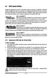
... key to an independent IDE/SATA controller, use FAT32/16/12 file system. 3. Additionally, this motherboard features the DualBIOSTM design, which enhances protection for the safety and stability of your floppy disk, USB flash drive, or hard drive. Normally, the system works on the next system boot and copy the BIOS file to the main BIOS to enter operating systems like MS-DOS or Window first. From GIGABYTE's website, download the latest compressed BIOS update file that support...
... key to an independent IDE/SATA controller, use FAT32/16/12 file system. 3. Additionally, this motherboard features the DualBIOSTM design, which enhances protection for the safety and stability of your floppy disk, USB flash drive, or hard drive. Normally, the system works on the next system boot and copy the BIOS file to the main BIOS to enter operating systems like MS-DOS or Window first. From GIGABYTE's website, download the latest compressed BIOS update file that support...

Manual
Page 71
... main menu of the system reading the BIOS file from the floppy disk is saved. The follow procedure assumes that you save the current BIOS file. • Q-Flash only supports USB flash drive or hard drives using FAT32/16/12 file system. • If the BIOS update file is saved to a hard drive in RAID/AHCI mode or a hard drive attached to an independent IDE/SATA controller, use the up or down arrow key to begin the BIOS update. Q-Flash Utility v2.05 Flash Type/Size MXIC 25L8005 1M Enter...
... main menu of the system reading the BIOS file from the floppy disk is saved. The follow procedure assumes that you save the current BIOS file. • Q-Flash only supports USB flash drive or hard drives using FAT32/16/12 file system. • If the BIOS update file is saved to a hard drive in RAID/AHCI mode or a hard drive attached to an independent IDE/SATA controller, use the up or down arrow key to begin the BIOS update. Q-Flash Utility v2.05 Flash Type/Size MXIC 25L8005 1M Enter...
Manual
Page 74
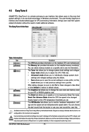
... install additional software. Smart Fan Advance Mode allows the CPU fan speed to be sure to click Go for CPU and memory information, lettings users read their system settings or do the overclock/overvoltage, make sure that the item is not configurable or the function is a simple and easy-to-use your ATI or NVIDIA graphics card. Grayed-out area(s) indicates that you to individually change the core clock and memory clock...
... install additional software. Smart Fan Advance Mode allows the CPU fan speed to be sure to click Go for CPU and memory information, lettings users read their system settings or do the overclock/overvoltage, make sure that the item is not configurable or the function is a simple and easy-to-use your ATI or NVIDIA graphics card. Grayed-out area(s) indicates that you to individually change the core clock and memory clock...

Manual
Page 87
... your motherboard has a clearing CMOS jumper, refer to the instructions on GIGABYTE's website. If not, try a speaker with an internal amplifier. A: The following Award BIOS beep code descriptions may help you identify possible computer problems. (For reference only.) 1 short: System boots successfully 2 short: CMOS setting error 1 long, 1 short: Memory or motherboard error 1 long, 2 short: Monitor or graphics card error 1 long, 3 short: Keyboard error 1 long, 9 short: BIOS ROM error Continuous long beeps: Graphics card not inserted properly Continuous short beeps: Power error - 87...
... your motherboard has a clearing CMOS jumper, refer to the instructions on GIGABYTE's website. If not, try a speaker with an internal amplifier. A: The following Award BIOS beep code descriptions may help you identify possible computer problems. (For reference only.) 1 short: System boots successfully 2 short: CMOS setting error 1 long, 1 short: Memory or motherboard error 1 long, 2 short: Monitor or graphics card error 1 long, 3 short: Keyboard error 1 long, 9 short: BIOS ROM error Continuous long beeps: Graphics card not inserted properly Continuous short beeps: Power error - 87...


