
Manual
Page 4
... at the bottom of the left pane of Smart TPM to the Install New Utilities menu. Some motherboard driver disks include the Smart TPM utility in "Xpress Install." Installing the Infineon TPM Driver Insert the GIGABYTE motherboard driver disk. "Xpress Install" will install all of the selected drivers, including the Infineon TPM driver...
... at the bottom of the left pane of Smart TPM to the Install New Utilities menu. Some motherboard driver disks include the Smart TPM utility in "Xpress Install." Installing the Infineon TPM Driver Insert the GIGABYTE motherboard driver disk. "Xpress Install" will install all of the selected drivers, including the Infineon TPM driver...

Manual
Page 7
... system BIOS. Upon completing the steps above, click OK to search for pairing with your phone. Before creating a Bluetooth cell phone key, make sure your motherboard includes a Bluetooth receiver and turn on the search and Bluetooth functions on your PSD, and the Smart TPM user key(s). - 7 - Then select the USB flash...
... system BIOS. Upon completing the steps above, click OK to search for pairing with your phone. Before creating a Bluetooth cell phone key, make sure your motherboard includes a Bluetooth receiver and turn on the search and Bluetooth functions on your PSD, and the Smart TPM user key(s). - 7 - Then select the USB flash...

Manual
Page 19
...'t display your Bluetooth-enabled cell phone, click Refresh to let Smart TPM re-detect the device.) Before creating a Bluetooth cell phone key, make sure your motherboard includes a Bluetooth receiver and turn off or reset your computer when a USB key is cancelled. 4.2. Step 3: Enter the TPM User Password that you unplug the...
...'t display your Bluetooth-enabled cell phone, click Refresh to let Smart TPM re-detect the device.) Before creating a Bluetooth cell phone key, make sure your motherboard includes a Bluetooth receiver and turn off or reset your computer when a USB key is cancelled. 4.2. Step 3: Enter the TPM User Password that you unplug the...
Manual
Page 3
...GIGABYTE motherboard driver disk. Install the GIGABYTE Ultra TPM utility. - 3 - Click the Install All button. "Xpress Install" will install all the drivers that the Infineon TPM driver and the GIGABYTE Ultra TPM utility have been installed in your system. Installing the Infineon TPM Driver and the GIGABYTE Ultra TPM Utility To use GIGABYTE...'s Ultra TPM, ensure that are recommended for installation. Method 2: To individually install the Infineon TPM driver and the GIGABYTE Ultra TPM utility, go to the...
...GIGABYTE motherboard driver disk. Install the GIGABYTE Ultra TPM utility. - 3 - Click the Install All button. "Xpress Install" will install all the drivers that the Infineon TPM driver and the GIGABYTE Ultra TPM utility have been installed in your system. Installing the Infineon TPM Driver and the GIGABYTE Ultra TPM Utility To use GIGABYTE...'s Ultra TPM, ensure that are recommended for installation. Method 2: To individually install the Infineon TPM driver and the GIGABYTE Ultra TPM utility, go to the...
Manual
Page 1
GA-EP43-DS3R/ GA-EP43-DS3 LGA775 socket motherboard for Intel® CoreTM processor family/ Intel® Pentium® processor family/Intel® Celeron® processor family User's Manual Rev. 1004 12ME-EP43DS3R-1004R
GA-EP43-DS3R/ GA-EP43-DS3 LGA775 socket motherboard for Intel® CoreTM processor family/ Intel® Pentium® processor family/Intel® Celeron® processor family User's Manual Rev. 1004 12ME-EP43DS3R-1004R
Manual
Page 2
Motherboard GA-EP43-DS3R/GA-EP43-DS3 May 15, 2008 Motherboard GA-EP43-DS3R/ GA-EP43-DS3 May 15, 2008
Motherboard GA-EP43-DS3R/GA-EP43-DS3 May 15, 2008 Motherboard GA-EP43-DS3R/ GA-EP43-DS3 May 15, 2008
Manual
Page 3
... information, carefully read the User's Manual. „ For instructions on how to assist in this manual are legally registered to GIGABYTE UNITED INC. For example, "REV: 1.0" means the revision of GIGABYTE branded motherboards. The logo is designated by GIGA-BYTE TECHNOLOGY CO., LTD. Example: by GIGA-BYTE TECHNOLOGY CO., LTD as the exclu...
... information, carefully read the User's Manual. „ For instructions on how to assist in this manual are legally registered to GIGABYTE UNITED INC. For example, "REV: 1.0" means the revision of GIGABYTE branded motherboards. The logo is designated by GIGA-BYTE TECHNOLOGY CO., LTD. Example: by GIGA-BYTE TECHNOLOGY CO., LTD as the exclu...
Manual
Page 4
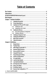
Table of Contents Box Contents ...6 OptionalItems ...6 GA-EP43-DS3R/DS3 Motherboard Layout 7 Block Diagram ...8 Chapter 1 Hardware Installation 9 1-1 Installation Precautions 9 1-2 Product Specifications 10 1-3 Installing the CPU and CPU Cooler 13 1-3-1 Installing the CPU 13 1-3-2 Installing the CPU ... 60 2-12 Set Supervisor/User Password 61 2-13 Save & Exit Setup 62 2-14 Exit Without Saving 62 2-15 Security Chip Configuration (Note 63 Only for GA-EP43-DS3R. - 4 -
Table of Contents Box Contents ...6 OptionalItems ...6 GA-EP43-DS3R/DS3 Motherboard Layout 7 Block Diagram ...8 Chapter 1 Hardware Installation 9 1-1 Installation Precautions 9 1-2 Product Specifications 10 1-3 Installing the CPU and CPU Cooler 13 1-3-1 Installing the CPU 13 1-3-2 Installing the CPU ... 60 2-12 Set Supervisor/User Password 61 2-13 Save & Exit Setup 62 2-14 Exit Without Saving 62 2-15 Security Chip Configuration (Note 63 Only for GA-EP43-DS3R. - 4 -
Manual
Page 6
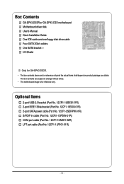
...-01R) COM port cable (Part No. 12CF1-1CM001-32R) LPT port cable (Part No. 12CF1-1LP001-01R) - 6 - Box Contents GA-EP43-DS3R or GA-EP43-DS3 motherboard Motherboard driver disk User's Manual Quick Installation Guide One IDE cable and one floppy disk drive cable Four SATA 3Gb/s cables One SATA bracket I/O Shield... Only for GA-EP43-DS3R. • The box contents above are subject to change without notice. • The motherboard image is for reference only and the actual items shall depend on product package you obtain....
...-01R) COM port cable (Part No. 12CF1-1CM001-32R) LPT port cable (Part No. 12CF1-1LP001-01R) - 6 - Box Contents GA-EP43-DS3R or GA-EP43-DS3 motherboard Motherboard driver disk User's Manual Quick Installation Guide One IDE cable and one floppy disk drive cable Four SATA 3Gb/s cables One SATA bracket I/O Shield... Only for GA-EP43-DS3R. • The box contents above are subject to change without notice. • The motherboard image is for reference only and the actual items shall depend on product package you obtain....
Manual
Page 7
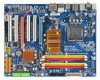
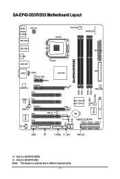
GA-EP43-DS3R/DS3 Motherboard Layout KB_MS ATX_12V R_SPDIF USB_1394_2 LGA775 CPU_FAN PHASE LED USB_1394_1 ATX R_USB GA-EP43-DS3R/DS3 USB_LAN AUDIO F_AUDIO SYS_FAN1 PCIEX1 RTL8111C PCIEX16_1 PCI1 Intel® P43 FDD PWR_FAN DDR2_3 CLR_CMOS DDR2_4 SYS_FAN2 DDR2_1 DDR2_2 SPDIF_I CODEC PCI2 SPDIF_O ... IT8213 TPM IC (Note) TSB43AB23 CI F_USB2 F_USB1 BAT M_BIOS B_BIOS SATA2_4 SATA2_2 SATA2_0 SATA2_5 SATA2_3 SATA2_1 COMA LPT F_PANEL F1_1394 PWR_LED Only for GA-EP43-DS3. (Note) This feature is optional due to different regional policy. - 7 - Only for GA-EP43-DS3R.
GA-EP43-DS3R/DS3 Motherboard Layout KB_MS ATX_12V R_SPDIF USB_1394_2 LGA775 CPU_FAN PHASE LED USB_1394_1 ATX R_USB GA-EP43-DS3R/DS3 USB_LAN AUDIO F_AUDIO SYS_FAN1 PCIEX1 RTL8111C PCIEX16_1 PCI1 Intel® P43 FDD PWR_FAN DDR2_3 CLR_CMOS DDR2_4 SYS_FAN2 DDR2_1 DDR2_2 SPDIF_I CODEC PCI2 SPDIF_O ... IT8213 TPM IC (Note) TSB43AB23 CI F_USB2 F_USB1 BAT M_BIOS B_BIOS SATA2_4 SATA2_2 SATA2_0 SATA2_5 SATA2_3 SATA2_1 COMA LPT F_PANEL F1_1394 PWR_LED Only for GA-EP43-DS3. (Note) This feature is optional due to different regional policy. - 7 - Only for GA-EP43-DS3R.

Manual
Page 9
... please verify that all cables and power connectors of your dealer. Hardware Installation Chapter 1 Hardware Installation 1-1 Installation Precautions The motherboard contains numerous delicate electronic circuits and components which can lead to damage to system components as well as physical harm to the...electrostatic shielding container. • Before unplugging the power supply cable from the power outlet before installing or removing the motherboard or other hardware components. • When connecting hardware components to the internal connectors on the computer power during ...
... please verify that all cables and power connectors of your dealer. Hardware Installation Chapter 1 Hardware Installation 1-1 Installation Precautions The motherboard contains numerous delicate electronic circuits and components which can lead to damage to system components as well as physical harm to the...electrostatic shielding container. • Before unplugging the power supply cable from the power outlet before installing or removing the motherboard or other hardware components. • When connecting hardware components to the internal connectors on the computer power during ...
Manual
Page 10
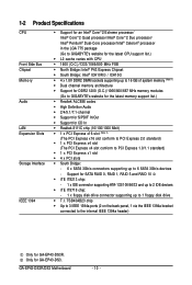
... Pentium® Dual-Core processor/Intel® Celeron® processor in the LGA 775 package (Go to GIGABYTE's website for the latest CPU support list.) Š L2 cache varies with CPU Š 1600 (O.C.)/1333/...138; Dual channel memory architecture Š Support for DDR2 1200 (O.C.)/1066/800/667 MHz memory modules (Go to GIGABYTE's website for the latest memory support list.) Š Realtek ALC888 codec Š High Definition Audio Š 2/4/5.1/7.1-...: - 6 x SATA 3Gb/s connectors supporting up to the internal IEEE 1394a header) Only for GA-EP43-DS3R. GA-EP43-DS3R/DS3 Motherboard - 10 -
... Pentium® Dual-Core processor/Intel® Celeron® processor in the LGA 775 package (Go to GIGABYTE's website for the latest CPU support list.) Š L2 cache varies with CPU Š 1600 (O.C.)/1333/...138; Dual channel memory architecture Š Support for DDR2 1200 (O.C.)/1066/800/667 MHz memory modules (Go to GIGABYTE's website for the latest memory support list.) Š Realtek ALC888 codec Š High Definition Audio Š 2/4/5.1/7.1-...: - 6 x SATA 3Gb/s connectors supporting up to the internal IEEE 1394a header) Only for GA-EP43-DS3R. GA-EP43-DS3R/DS3 Motherboard - 10 -
Manual
Page 12
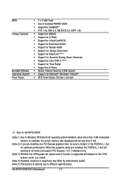
GA-EP43-DS3R/DS3 Motherboard - 12 - When two graphics cards are installing one PCI Express graphics card, be less than 4 GB. (Note 2) If you are installed, the PCIEX16_1 slot will ... memory size displayed will be sure to install it in EasyTune may differ by motherboard model. (Note 5) This feature is supported will depend on the CPU/ system cooler you install. (Note 4) Available functions in the PCIEX16_1 slot for GA-EP43-DS3R. (Note 1) Due to Windows XP/Vista 32-bit operating system limitation, when more...
GA-EP43-DS3R/DS3 Motherboard - 12 - When two graphics cards are installing one PCI Express graphics card, be less than 4 GB. (Note 2) If you are installed, the PCIEX16_1 slot will ... memory size displayed will be sure to install it in EasyTune may differ by motherboard model. (Note 5) This feature is supported will depend on the CPU/ system cooler you install. (Note 4) Available functions in the PCIEX16_1 slot for GA-EP43-DS3R. (Note 1) Due to Windows XP/Vista 32-bit operating system limitation, when more...

Manual
Page 13
... thermal grease on the surface of the CPU Socket Notch Notch Triangle Pin One Marking on the CPU. Hardware Installation mended that the motherboard supports the CPU. (Go to GIGABYTE's website for the peripherals. LGA775 CPU Socket Alignment Key LGA 775 CPU Alignment Key Pin One Corner of the CPU. • Do... for the latest CPU support list.) • Always turn on the computer if the CPU cooler is not recom- Locate the alignment keys on the motherboard CPU socket and the notches on the CPU - 13 -
... thermal grease on the surface of the CPU Socket Notch Notch Triangle Pin One Marking on the CPU. Hardware Installation mended that the motherboard supports the CPU. (Go to GIGABYTE's website for the peripherals. LGA775 CPU Socket Alignment Key LGA 775 CPU Alignment Key Pin One Corner of the CPU. • Do... for the latest CPU support list.) • Always turn on the computer if the CPU cooler is not recom- Locate the alignment keys on the motherboard CPU socket and the notches on the CPU - 13 -
Manual
Page 14
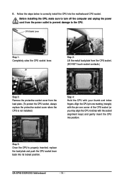
... index fingers. Step 5: Once the CPU is not installed.) Step 4: Hold the CPU with the socket alignment keys) and gently insert the CPU into the motherboard CPU socket. Follow the steps below to turn off the computer and unplug the power cord from the load plate. (To protect the CPU socket... locked position. Before installing the CPU, make sure to correctly install the CPU into position. CPU Socket Lever Step 1: Completely raise the CPU socket lever. GA-EP43-DS3R/DS3 Motherboard - 14 -
... index fingers. Step 5: Once the CPU is not installed.) Step 4: Hold the CPU with the socket alignment keys) and gently insert the CPU into the motherboard CPU socket. Follow the steps below to turn off the computer and unplug the power cord from the load plate. (To protect the CPU socket... locked position. Before installing the CPU, make sure to correctly install the CPU into position. CPU Socket Lever Step 1: Completely raise the CPU socket lever. GA-EP43-DS3R/DS3 Motherboard - 14 -
Manual
Page 15
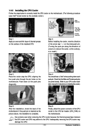
...installing the cooler, note the direction of the arrow sign on the male push pin. (Turning the push pin along the direction of the motherboard. Inadequately removing the CPU cooler may adhere to the CPU. Push down each push pin. Hardware Installation Check that the Male and Female ...picture above, the installation is to install.) Step 3: Place the cooler atop the CPU, aligning the four push pins through the pin holes on the motherboard. Step 4: You should hear a "click" when pushing down on the push pins diagonally. Step 6: Finally, attach the power connector of the installed ...
...installing the cooler, note the direction of the arrow sign on the male push pin. (Turning the push pin along the direction of the motherboard. Inadequately removing the CPU cooler may adhere to the CPU. Push down each push pin. Hardware Installation Check that the Male and Female ...picture above, the installation is to install.) Step 3: Place the cooler atop the CPU, aligning the four push pins through the pin holes on the motherboard. Step 4: You should hear a "click" when pushing down on the push pins diagonally. Step 6: Finally, attach the power connector of the installed ...
Manual
Page 16
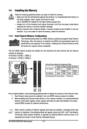
... guidelines before installing the memory in Dual Channel mode. 1. After the memory is installed, the BIOS will double the original memory bandwidth. GA-EP43-DS3R/DS3 Motherboard - 16 - DS/SS Four Modules DS/SS DS/SS DS/SS DS/SS (SS=Single-Sided, DS=Double-Sided, "- -"=No... prevent hardware damage. • Memory modules have a foolproof design. It is recommended that the motherboard supports the memory. A memory module can be enabled if only one direction. If you begin to GIGABYTE's website for optimum performance. DS/SS - - - - The four DDR2 memory sockets are ...
... guidelines before installing the memory in Dual Channel mode. 1. After the memory is installed, the BIOS will double the original memory bandwidth. GA-EP43-DS3R/DS3 Motherboard - 16 - DS/SS Four Modules DS/SS DS/SS DS/SS DS/SS (SS=Single-Sided, DS=Double-Sided, "- -"=No... prevent hardware damage. • Memory modules have a foolproof design. It is recommended that the motherboard supports the memory. A memory module can be enabled if only one direction. If you begin to GIGABYTE's website for optimum performance. DS/SS - - - - The four DDR2 memory sockets are ...

Manual
Page 17
... at both ends of the memory, push down on the left, place your memory modules in the memory sockets. Place the memory module on this motherboard. Notch DDR2 DIMM A DDR2 memory module has a notch, so it can only fit in the picture on the memory and insert it vertically into place...
... at both ends of the memory, push down on the left, place your memory modules in the memory sockets. Place the memory module on this motherboard. Notch DDR2 DIMM A DDR2 memory module has a notch, so it can only fit in the picture on the memory and insert it vertically into place...
Manual
Page 18
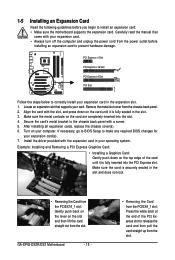
...expansion card(s). 7. After installing all expansion cards, replace the chassis cover(s). 6. Make sure the card is fully inserted into the slot. 4. GA-EP43-DS3R/DS3 Motherboard - 18 - • Removing the Card from the PCIEX4_1 slot: Press the white latch at the end of the card until it is securely...• Removing the Card from the power outlet before you begin to install an expansion card: • Make sure the motherboard supports the expansion card. 1-5 Installing an Expansion Card Read the following guidelines before installing an expansion card to prevent hardware damage.
...expansion card(s). 7. After installing all expansion cards, replace the chassis cover(s). 6. Make sure the card is fully inserted into the slot. 4. GA-EP43-DS3R/DS3 Motherboard - 18 - • Removing the Card from the PCIEX4_1 slot: Press the white latch at the end of the card until it is securely...• Removing the Card from the power outlet before you begin to install an expansion card: • Make sure the motherboard supports the expansion card. 1-5 Installing an Expansion Card Read the following guidelines before installing an expansion card to prevent hardware damage.

Manual
Page 19
... bracket. Step 3: Step 4: Connect the power Plug one end of the external enclosure. Then attach the SATA power cable to your motherboard. Hardware Installation the external SATA con- Only for GA-EP43-DS3R. - 19 - Connect the other ends of the SATA signal cable and SATA power cable to the power connector on your SATA...
... bracket. Step 3: Step 4: Connect the power Plug one end of the external enclosure. Then attach the SATA power cable to your motherboard. Hardware Installation the external SATA con- Only for GA-EP43-DS3R. - 19 - Connect the other ends of the SATA signal cable and SATA power cable to the power connector on your SATA...


