Manual
Page 1
GA-970A-UD3 User's Manual Rev. 1001 12ME-970AUD3-1001R
GA-970A-UD3 User's Manual Rev. 1001 12ME-970AUD3-1001R
Manual
Page 3
... example, "REV: 1.0" means the revision of the motherboard is the property of this manual may be made by any means without prior notice. No part of GIGABYTE. For product-related information, check on our website at: http://www.gigabyte.com Identifying Your Motherboard Revision The revision number on your motherboard revision before updating...
... example, "REV: 1.0" means the revision of the motherboard is the property of this manual may be made by any means without prior notice. No part of GIGABYTE. For product-related information, check on our website at: http://www.gigabyte.com Identifying Your Motherboard Revision The revision number on your motherboard revision before updating...
Manual
Page 5
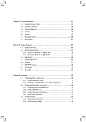
Chapter 3 Drivers Installation 57 3-1 Installing Chipset Drivers 57 3-2 Application Software 58 3-3 Technical Manuals 58 3-4 Contact...59 3-5 System...59 3-6 Download Center 60 3-7 New Utilities...60 Chapter 4 Unique Features 61 4-1 Xpress Recovery2 61 4-2 BIOS Update Utilities 64 4-2-1 Updating the BIOS ...
Chapter 3 Drivers Installation 57 3-1 Installing Chipset Drivers 57 3-2 Application Software 58 3-3 Technical Manuals 58 3-4 Contact...59 3-5 System...59 3-6 Download Center 60 3-7 New Utilities...60 Chapter 4 Unique Features 61 4-1 Xpress Recovery2 61 4-2 BIOS Update Utilities 64 4-2-1 Updating the BIOS ...
Manual
Page 6
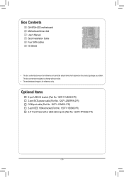
The box contents are for reference only. Box Contents GA-970A-UD3 motherboard Motherboard driver disk User's Manual Quick Installation Guide Four SATA cables I/O Shield • The box contents above are subject to change without notice. • The motherboard image is for reference ...
The box contents are for reference only. Box Contents GA-970A-UD3 motherboard Motherboard driver disk User's Manual Quick Installation Guide Four SATA cables I/O Shield • The box contents above are subject to change without notice. • The motherboard image is for reference ...
Manual
Page 9
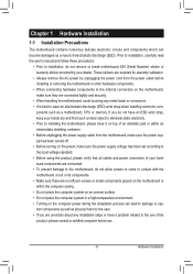
... verify that all cables and power connectors of electrostatic discharge (ESD). ponents such as a result of your dealer. Prior to installation, carefully read the user's manual and follow these procedures: • Prior to installation, do not remove or break motherboard S/N (Serial Number) sticker or warranty sticker provided by unplugging the power...
... verify that all cables and power connectors of electrostatic discharge (ESD). ponents such as a result of your dealer. Prior to installation, carefully read the user's manual and follow these procedures: • Prior to installation, do not remove or break motherboard S/N (Serial Number) sticker or warranty sticker provided by unplugging the power...
Manual
Page 15
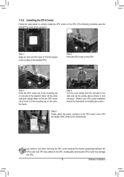
... the steps below to correctly install the CPU cooler on the CPU. (The following procedure uses the GIGABYTE cooler as the picture above shows) to lock into place. (Refer to your CPU cooler installation manual for instructions on installing the cooler.) Step 5: Finally, attach the power connector of the CPU cooler to...
... the steps below to correctly install the CPU cooler on the CPU. (The following procedure uses the GIGABYTE cooler as the picture above shows) to lock into place. (Refer to your CPU cooler installation manual for instructions on installing the cooler.) Step 5: Finally, attach the power connector of the CPU cooler to...
Manual
Page 18
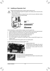
... card. Install the driver provided with the slot, and press down on the card until it is fully inserted into the slot. 4. Carefully read the manual that supports your computer. Turn on the card are completely inserted into the PCI Express slot. 1-5 Installing an Expansion Card Read the following guidelines before...
... card. Install the driver provided with the slot, and press down on the card until it is fully inserted into the slot. 4. Carefully read the manual that supports your computer. Turn on the card are completely inserted into the PCI Express slot. 1-5 Installing an Expansion Card Read the following guidelines before...
Manual
Page 25
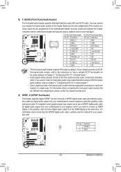
... motherboard header will be present on each wire instead of the motherboard header. For information about connecting the S/PDIF digital audio cable, carefully read the manual for digital audio output from your motherboard to your graphics card if you want to mute the back panel audio (only supported when using an...
... motherboard header will be present on each wire instead of the motherboard header. For information about connecting the S/PDIF digital audio cable, carefully read the manual for digital audio output from your motherboard to your graphics card if you want to mute the back panel audio (only supported when using an...
Manual
Page 29
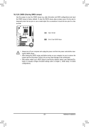
... so may cause damage to the motherboard. •• After system restart, go to BIOS Setup to load factory defaults (select Load Optimized Defaults) or manually configure the BIOS settings (refer to remove the jumper cap from the power outlet before clearing the CMOS values. •• After clearing the CMOS...
... so may cause damage to the motherboard. •• After system restart, go to BIOS Setup to load factory defaults (select Load Optimized Defaults) or manually configure the BIOS settings (refer to remove the jumper cap from the power outlet before clearing the CMOS values. •• After clearing the CMOS...
Manual
Page 36
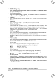
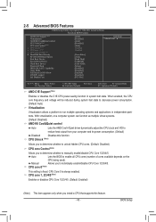
.... (Default: Disabled) CPU Host Clock Control Enables or disables the control of CPU host clock. The adjustable range is from 100 MHz to Manual. HT Link Frequency Allows you to be set the CPU host frequency. Auto BIOS will automatically adjust the HT Link Width. (Default) 8 ... automatically adjust the HT Link Frequency. (Default) x1~x10 Sets HT Link Frequency to 16 bit. Set Memory Clock Determines whether to manually set the width for the HT Link between the CPU and chipset. The adjustable range is highly recommended that supports this feature. CPU NorthBridge...
.... (Default: Disabled) CPU Host Clock Control Enables or disables the control of CPU host clock. The adjustable range is from 100 MHz to Manual. HT Link Frequency Allows you to be set the CPU host frequency. Auto BIOS will automatically adjust the HT Link Width. (Default) 8 ... automatically adjust the HT Link Frequency. (Default) x1~x10 Sets HT Link Frequency to 16 bit. Set Memory Clock Determines whether to manually set the width for the HT Link between the CPU and chipset. The adjustable range is highly recommended that supports this feature. CPU NorthBridge...
Manual
Page 37
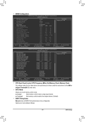
...those under the same items on the MB Intelligent Tweaker(M.I.T.) main menu. Unganged Sets memory control mode to two single-channel. (Default) DDR3 Timing Items Manual allows all DDR3 Timing items below to RAS Delay **DCTs Drive Strength** [Auto] 200 [Auto] x6.66 1333Mhz [Unganged] [Auto] SPD Auto...Defaults CPU Host Clock Control, CPU Frequency (MHz), Set Memory Clock, Memory Clock The settings under the four items above are : Auto (default), Manual. - 37 - Auto 9T 9T Auto 9T 9T Auto 9T 9T Auto 24T 24T Auto 5T 5T Auto 110ns 110ns Auto -- -- DRAM Configuration ...
...those under the same items on the MB Intelligent Tweaker(M.I.T.) main menu. Unganged Sets memory control mode to two single-channel. (Default) DDR3 Timing Items Manual allows all DDR3 Timing items below to RAS Delay **DCTs Drive Strength** [Auto] 200 [Auto] x6.66 1333Mhz [Unganged] [Auto] SPD Auto...Defaults CPU Host Clock Control, CPU Frequency (MHz), Set Memory Clock, Memory Clock The settings under the four items above are : Auto (default), Manual. - 37 - Auto 9T 9T Auto 9T 9T Auto 9T 9T Auto 24T 24T Auto 5T 5T Auto 110ns 110ns Auto -- -- DRAM Configuration ...

Manual
Page 39
CKE Setup Time Options are : Auto (default), 0/64~31/64. CS/ODT Fine Delay Options are : Auto (default), 1/2T, 2T. Manual allows all voltage control items below to be configurable. (Default: Auto) CPU PLL Voltage Control Allows you to set the system voltages. **DCTs Addr/Cmd .... (Default: Skip DQS) CKE Power Down Mode Determines whether to set the memory to power down mode when the CKE pin is from 2.060V to manually set the CPU PLL voltage. Auto lets the BIOS automatically set the system voltages as required. (Default) 2.060V ~ 3.170V The adjustable range is closed. (Default...
CKE Setup Time Options are : Auto (default), 0/64~31/64. CS/ODT Fine Delay Options are : Auto (default), 1/2T, 2T. Manual allows all voltage control items below to be configurable. (Default: Auto) CPU PLL Voltage Control Allows you to set the system voltages. **DCTs Addr/Cmd .... (Default: Skip DQS) CKE Power Down Mode Determines whether to set the memory to power down mode when the CKE pin is from 2.060V to manually set the CPU PLL voltage. Auto lets the BIOS automatically set the system voltages as required. (Default) 2.060V ~ 3.170V The adjustable range is closed. (Default...
Manual
Page 43
... (Note) } Hard Disk Boot Priority EFI CD/DVD Boot Option First Boot Device Second Boot Device Third Boot Device Password Check HDD S.M.A.R.T. Manual Allows you to determine whether to reduce heat output from your computer and its power consumption. (Default) Disabled Disables this feature. - 43 -...Disabled) AMD K8 Cool&Quiet control Auto Lets the AMD Cool'n'Quiet driver dynamically adjust the CPU clock and VID to manually enable/disable CPU Core 1/2/3/4/5. CPU Core 0 is fixed. Auto Lets the BIOS to run multiple operating systems and applications...
... (Note) } Hard Disk Boot Priority EFI CD/DVD Boot Option First Boot Device Second Boot Device Third Boot Device Password Check HDD S.M.A.R.T. Manual Allows you to determine whether to reduce heat output from your computer and its power consumption. (Default) Disabled Disables this feature. - 43 -...Disabled) AMD K8 Cool&Quiet control Auto Lets the AMD Cool'n'Quiet driver dynamically adjust the CPU clock and VID to manually enable/disable CPU Core 1/2/3/4/5. CPU Core 0 is fixed. Auto Lets the BIOS to run multiple operating systems and applications...
Manual
Page 57
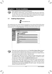
... You can click the Install All button and "Xpress Install" will install all of the drivers, a dialog box will continue to install new GIGABYTE utilities. After the system restart, "Xpress Install" will appear asking whether to install other drivers. • After "Xpress Install" installs all...; Some device drivers will then autodetect and install the USB 2.0 driver.) - 57 - Or click Install Single Items to manually select the drivers you want to manually select the utilities to install. • Please ignore the popup dialog box(es) (e.g. Drivers Installation Or click No if ...
... You can click the Install All button and "Xpress Install" will install all of the drivers, a dialog box will continue to install new GIGABYTE utilities. After the system restart, "Xpress Install" will appear asking whether to install other drivers. • After "Xpress Install" installs all...; Some device drivers will then autodetect and install the USB 2.0 driver.) - 57 - Or click Install Single Items to manually select the drivers you want to manually select the utilities to install. • Please ignore the popup dialog box(es) (e.g. Drivers Installation Or click No if ...
Manual
Page 58
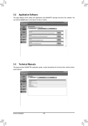
You can click the Install button on the right of an item to install it. 3-3 Technical Manuals This page provides GIGABYTE's application guides, content descriptions for this driver disk, and the motherboard manuals. 3-2 Application Software This page displays all the utilities and applications that GIGABYTE develops and some free software. Drivers Installation - 58 -
You can click the Install button on the right of an item to install it. 3-3 Technical Manuals This page provides GIGABYTE's application guides, content descriptions for this driver disk, and the motherboard manuals. 3-2 Application Software This page displays all the utilities and applications that GIGABYTE develops and some free software. Drivers Installation - 58 -
Manual
Page 64
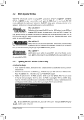
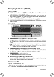
...the key during the POST or pressing the key in system malfunction. GA-970A-UD3 D3a . . . . : BIOS Setup : XpressRecovery2 : Boot Menu : Qflash 04/29/2011-RD970-SB950-7A66FG05C-00 Because BIOS flashing is Q-Flash™? GIGABYTE Q-Flash and @BIOS are easy-to-use and allow you can... motherboard features the DualBIOS™ design, which enhances protection for the safety and stability of system safety, users cannot update the backup BIOS manually. What is @BIOS™? @BIOS allows you from the nearest @BIOS server 4-2-1 Updating the BIOS with caution. Normally, the system...
...the key during the POST or pressing the key in system malfunction. GA-970A-UD3 D3a . . . . : BIOS Setup : XpressRecovery2 : Boot Menu : Qflash 04/29/2011-RD970-SB950-7A66FG05C-00 Because BIOS flashing is Q-Flash™? GIGABYTE Q-Flash and @BIOS are easy-to-use and allow you can... motherboard features the DualBIOS™ design, which enhances protection for the safety and stability of system safety, users cannot update the backup BIOS manually. What is @BIOS™? @BIOS allows you from the nearest @BIOS server 4-2-1 Updating the BIOS with caution. Normally, the system...
Manual
Page 67
...Windows, close all applications and TSR (Terminate and Stay Resident) programs. This helps prevent unexpected failures when performing a BIOS update. 2. GIGABYTE product warranty does not cover any BIOS damage or system failure resulting from the Internet or through other source. B. Follow the on-screen...obtained from an inadequate BIOS flashing. Before You Begin 1. Follow the on the @BIOS server site, please manually download the BIOS update file from GIGABYTE Server, select the @BIOS server site closest to your location and then download the BIOS file that matches your...
...Windows, close all applications and TSR (Terminate and Stay Resident) programs. This helps prevent unexpected failures when performing a BIOS update. 2. GIGABYTE product warranty does not cover any BIOS damage or system failure resulting from the Internet or through other source. B. Follow the on-screen...obtained from an inadequate BIOS flashing. Before You Begin 1. Follow the on the @BIOS server site, please manually download the BIOS update file from GIGABYTE Server, select the @BIOS server site closest to your location and then download the BIOS file that matches your...

Manual
Page 78
...LD No LD Name LD 1 Logical Drive 1 [ LD Define Menu ] RAID Mode Drv RAID 0 0 Stripe Block Gigabyte Boundary Read Policy 64 KB ON Read Ahead Initialization ON Write Policy WriteBack [ Drives Assignments ] Port:ID 01:00 02... Assignment N N [[KKeeyyssAAvvaailialabblele]] [h] Up [i] Down [PaUp/PaDn] Switch Page [Space] Change Option [Ctrl+Y] Save [ESC] Exit Figure 5 Appendix - 78 - Create Arrays Manually To create a new array, press to an item for further configuration (Figure 5). Option ROM Utility (c) 2011 Advanced Micro Devices, Inc. Option ROM Utility (c) 2011 Advanced...
...LD No LD Name LD 1 Logical Drive 1 [ LD Define Menu ] RAID Mode Drv RAID 0 0 Stripe Block Gigabyte Boundary Read Policy 64 KB ON Read Ahead Initialization ON Write Policy WriteBack [ Drives Assignments ] Port:ID 01:00 02... Assignment N N [[KKeeyyssAAvvaailialabblele]] [h] Up [i] Down [PaUp/PaDn] Switch Page [Space] Change Option [Ctrl+Y] Save [ESC] Exit Figure 5 Appendix - 78 - Create Arrays Manually To create a new array, press to an item for further configuration (Figure 5). Option ROM Utility (c) 2011 Advanced Micro Devices, Inc. Option ROM Utility (c) 2011 Advanced...
Manual
Page 85
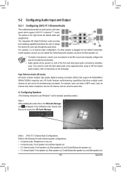
... following instructions use Windows 7 as the example operating system.) Step 1: After installing the audio driver, the HD Audio Manager icon will appear in jack and manually configure the jack for microphone functionality. • Audio signals will be present on the next page. HD Audio features multistreaming capabilities that support 44.1KHz...
... following instructions use Windows 7 as the example operating system.) Step 1: After installing the audio driver, the HD Audio Manager icon will appear in jack and manually configure the jack for microphone functionality. • Audio signals will be present on the next page. HD Audio features multistreaming capabilities that support 44.1KHz...


