
Manual
Page 1
GA-946GM-DS2/S2 (rev. 2.0) Intel® CoreTM 2 Extreme quad-core / CoreTM 2 Quad / Intel® CoreTM 2 Extreme dual-core / CoreTM 2 Duo / Intel® Pentium® Processor Extreme Edition / Intel® Pentium® D / Pentium® 4 LGA775 Processor Motherboard User's Manual Rev. 2002 12ME-946GMDR-2002R * The WEEE marking on the product indicates this product must not...
GA-946GM-DS2/S2 (rev. 2.0) Intel® CoreTM 2 Extreme quad-core / CoreTM 2 Quad / Intel® CoreTM 2 Extreme dual-core / CoreTM 2 Duo / Intel® Pentium® Processor Extreme Edition / Intel® Pentium® D / Pentium® 4 LGA775 Processor Motherboard User's Manual Rev. 2002 12ME-946GMDR-2002R * The WEEE marking on the product indicates this product must not...
Manual
Page 2
Motherboard GA-946GM-DS2/GA-946GM-S2 (rev. 2.0) Oct. 20, 2006 Motherboard GA-946GM-DS2/ GA-946GM-S2 (rev. 2.0) Oct. 20, 2006
Motherboard GA-946GM-DS2/GA-946GM-S2 (rev. 2.0) Oct. 20, 2006 Motherboard GA-946GM-DS2/ GA-946GM-S2 (rev. 2.0) Oct. 20, 2006
Manual
Page 4
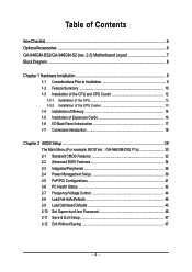
Table of Contents ItemChecklist ...6 OptionalAccessories ...6 GA-946GM-DS2/GA-946GM-S2 (rev. 2.0) Motherboard Layout 7 Block Diagram ...8 Chapter 1 Hardware Installation 9 1-1 Considerations Prior to Installation 9 1-2 Feature Summary 10 1-3 Installation of the CPU...Expansion Cards 16 1-6 I/O Back Panel Introduction 17 1-7 Connectors Introduction 18 Chapter 2 BIOS Setup 29 The Main Menu (For example: BIOS Ver. : GA-946GM-DS2 F1a 30 2-1 Standard CMOS Features 32 2-2 Advanced BIOS Features 34 2-3 IntegratedPeripherals 36 2-4 Power Management Setup 39 2-5 PnP/PCI Configurations 41 2-6...
Table of Contents ItemChecklist ...6 OptionalAccessories ...6 GA-946GM-DS2/GA-946GM-S2 (rev. 2.0) Motherboard Layout 7 Block Diagram ...8 Chapter 1 Hardware Installation 9 1-1 Considerations Prior to Installation 9 1-2 Feature Summary 10 1-3 Installation of the CPU...Expansion Cards 16 1-6 I/O Back Panel Introduction 17 1-7 Connectors Introduction 18 Chapter 2 BIOS Setup 29 The Main Menu (For example: BIOS Ver. : GA-946GM-DS2 F1a 30 2-1 Standard CMOS Features 32 2-2 Advanced BIOS Features 34 2-3 IntegratedPeripherals 36 2-4 Power Management Setup 39 2-5 PnP/PCI Configurations 41 2-6...
Manual
Page 7
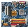
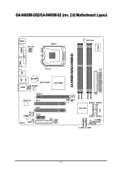
GA-946GM-DS2/GA-946GM-S2 (rev. 2.0) Motherboard Layout VGA KB_MS ATX_12V LGA775 CPU_FAN GA-946GM-DS2/GA-946GM-S2 IT8718 COMA LPT USB USB AUDIO LAN BATTERY SYS_FAN CLR_CMOS Intel® 946GZ F_AUDIO PCIE_16 RTL8111B PCI1 BIOS PCI2 CD_IN CODEC PCIE_1 REV: 2.0 SPDIF_IO FDD COMB DDRII1 DDRII2 DDRII3 DDRII4 ATX IDE SATAII2 SATAII3 Intel® ICH7 CI SATAII0 SATAII1 F_PANEL PWR_LED F_USB1 F_USB2 - 7 -
GA-946GM-DS2/GA-946GM-S2 (rev. 2.0) Motherboard Layout VGA KB_MS ATX_12V LGA775 CPU_FAN GA-946GM-DS2/GA-946GM-S2 IT8718 COMA LPT USB USB AUDIO LAN BATTERY SYS_FAN CLR_CMOS Intel® 946GZ F_AUDIO PCIE_16 RTL8111B PCI1 BIOS PCI2 CD_IN CODEC PCIE_1 REV: 2.0 SPDIF_IO FDD COMB DDRII1 DDRII2 DDRII3 DDRII4 ATX IDE SATAII2 SATAII3 Intel® ICH7 CI SATAII0 SATAII1 F_PANEL PWR_LED F_USB1 F_USB2 - 7 -
Manual
Page 8
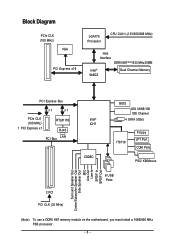
... Center/Subwoofer Speaker Out Side Speaker Out MIC Line-Out Line-In SPDIF In SPDIF Out (Note) To use a DDRII 667 memory module on the motherboard, you must install a 1066/800 MHz FSB processor. - 8 -
... Center/Subwoofer Speaker Out Side Speaker Out MIC Line-Out Line-In SPDIF In SPDIF Out (Note) To use a DDRII 667 memory module on the motherboard, you must install a 1066/800 MHz FSB processor. - 8 -

Manual
Page 9
... components, please have a problem related to improper installation. 4. Prior to be an unofficial Gigabyte product. - 9 - To prevent damage to use of an antistatic pad or within the computer casing. 6. Please do not place the computer system on the motherboard. Damage as physical harm to wear an electrostatic discharge (ESD) cuff when handling...
... components, please have a problem related to improper installation. 4. Prior to be an unofficial Gigabyte product. - 9 - To prevent damage to use of an antistatic pad or within the computer casing. 6. Please do not place the computer system on the motherboard. Damage as physical harm to wear an electrostatic discharge (ESD) cuff when handling...

Manual
Page 10
...; 1 S/PDIF In/Out connector Š 1 COMB connector Š 2 USB 2.0/1.1 connectors for additional 4 ports by cables Š 1 power LED connector Š 1 Chassis Intrusion connector "*" Only the GA-946GM-DS2 adopts All-Solid Capacitor design. GA-946GM-DS2/S2 (rev. 2.0) Motherboard - 10 -
...; 1 S/PDIF In/Out connector Š 1 COMB connector Š 2 USB 2.0/1.1 connectors for additional 4 ports by cables Š 1 power LED connector Š 1 Chassis Intrusion connector "*" Only the GA-946GM-DS2 adopts All-Solid Capacitor design. GA-946GM-DS2/S2 (rev. 2.0) Motherboard - 10 -
Manual
Page 11
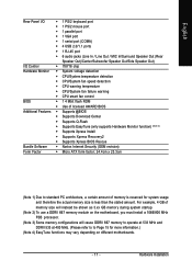
... BIOS Š 1 4 Mbit flash ROM Š Use of memory is reserved for more information.) (Note 4) EasyTune functions may vary depending on the motherboard, you must install a 1066/800 MHz FSB processor. (Note 3) Some memory configurations will instead be shown as 3.xx GB memory during system startup. ...(Note 2) To use a DDRII 667 memory module on different motherboards. - 11 - Hardware Installation For example, 4 GB of memory size will cause DDRII 667 memory to operate at 533 MHz and DDRII 533 at...
... BIOS Š 1 4 Mbit flash ROM Š Use of memory is reserved for more information.) (Note 4) EasyTune functions may vary depending on the motherboard, you must install a 1066/800 MHz FSB processor. (Note 3) Some memory configurations will instead be shown as 3.xx GB memory during system startup. ...(Note 2) To use a DDRII 667 memory module on different motherboards. - 11 - Hardware Installation For example, 4 GB of memory size will cause DDRII 667 memory to operate at 533 MHz and DDRII 533 at...
Manual
Page 12
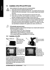
... the proper specifications, please do so according to set beyond hardware specifications since it enabled - It is not recommended that the motherboard supports the CPU. 2. Avoid twisting or bending motions that supports HT Technology - Fig. 2 Remove the plastic covering on the... the CPU Metal Lever Fig. 1 Gently lift the metal lever located on the CPU prior to the CPU during installation.) GA-946GM-DS2/S2 (rev. 2.0) Motherboard - 12 - HT functionality requirement content : Enabling the functionality of Hyper-Threading Technology for HT Technology 1-3-1 Installation of heat ...
... the proper specifications, please do so according to set beyond hardware specifications since it enabled - It is not recommended that the motherboard supports the CPU. 2. Avoid twisting or bending motions that supports HT Technology - Fig. 2 Remove the plastic covering on the... the CPU Metal Lever Fig. 1 Gently lift the metal lever located on the CPU prior to the CPU during installation.) GA-946GM-DS2/S2 (rev. 2.0) Motherboard - 12 - HT functionality requirement content : Enabling the functionality of Hyper-Threading Technology for HT Technology 1-3-1 Installation of heat ...
Manual
Page 13
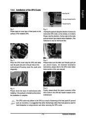
If the push pin is inserted as a result of hardening of motherboard after installing. The CPU cooler may adhere to the CPU as the picture, the installation is suggested that either thermal tape rather than heat paste ... - Fig. 6 Finally, please attach the power connector of the installed CPU. Fig. 4 Please make sure the push pins aim to the pin hole on the motherboard.Pressing down the push pins diagonally. English 1-3-2 Installation of the CPU Cooler Male Push Pin The top of Female Push Pin Female Push Pin Fig...
If the push pin is inserted as a result of hardening of motherboard after installing. The CPU cooler may adhere to the CPU as the picture, the installation is suggested that either thermal tape rather than heat paste ... - Fig. 6 Finally, please attach the power connector of the installed CPU. Fig. 4 Please make sure the push pins aim to the pin hole on the motherboard.Pressing down the push pins diagonally. English 1-3-2 Installation of the CPU Cooler Male Push Pin The top of Female Push Pin Female Push Pin Fig...
Manual
Page 14
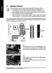
... modules, please make sure that the computer power is recommended that they can be inserted only in only one direction. The motherboard supports DDRII memory modules, whereby BIOS will automatically detect memory capacity and specifications. Notch DDRII Fig.1 The DIMM socket has a...capacity, specifications and brand be used can only fit in one direction. The memory capacity used . 2. Then push it down. GA-946GM-DS2/S2 (rev. 2.0) Motherboard - 14 - A memory module can be installed in one direction. Insert the DIMM memory module vertically into the DIMM socket. Fig...
... modules, please make sure that the computer power is recommended that they can be inserted only in only one direction. The motherboard supports DDRII memory modules, whereby BIOS will automatically detect memory capacity and specifications. Notch DDRII Fig.1 The DIMM socket has a...capacity, specifications and brand be used can only fit in one direction. The memory capacity used . 2. Then push it down. GA-946GM-DS2/S2 (rev. 2.0) Motherboard - 14 - A memory module can be installed in one direction. Insert the DIMM memory module vertically into the DIMM socket. Fig...

Manual
Page 16
... bar. Replace the screw to secure the slot bracket of the PCI Express x16 slot when you try to install/ uninstall the VGA card. GA-946GM-DS2/S2 (rev. 2.0) Motherboard - 16 - Install related driver from BIOS. 8. Remove your computer's chassis cover. 7. Installing a PCI Express x16 expansion card: Please carefully pull out the small whitedrawable...
... bar. Replace the screw to secure the slot bracket of the PCI Express x16 slot when you try to install/ uninstall the VGA card. GA-946GM-DS2/S2 (rev. 2.0) Motherboard - 16 - Install related driver from BIOS. 8. Remove your computer's chassis cover. 7. Installing a PCI Express x16 expansion card: Please carefully pull out the small whitedrawable...

Manual
Page 18
... Connector) 3) CPU_FAN 4) SYS_FAN 5) FDD 6) IDE 7) SATAII0/1/2/3 8) F_PANEL 9) F_AUDIO 10) PWR_LED 11) CD_IN 12) SPDIF_IO 13) F_USB1/F_USB2 14) COMB 15) CI 16) CLR_CMOS 17) BATTERY GA-946GM-DS2/S2 (rev. 2.0) Motherboard - 18 - Please refer to the 2-/4-/6-/8-
... Connector) 3) CPU_FAN 4) SYS_FAN 5) FDD 6) IDE 7) SATAII0/1/2/3 8) F_PANEL 9) F_AUDIO 10) PWR_LED 11) CD_IN 12) SPDIF_IO 13) F_USB1/F_USB2 14) COMB 15) CI 16) CLR_CMOS 17) BATTERY GA-946GM-DS2/S2 (rev. 2.0) Motherboard - 18 - Please refer to the 2-/4-/6-/8-

Manual
Page 19
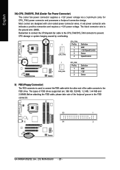
...devices are properly installed. If the ATX_12V power connector is recommended that a power supply that all the components on the motherboard. Before connecting the power connector, please make sure that can withstand high power consumption be used that does not provide ... power to handle the system voltage requirements. Please use a 24-pin ATX power supply, please remove the small cover on the power connector on the motherboard and connect tightly. Otherwise, please do not remove it. 2 1 4 3 ATX_12V Pin No. 1 2 3 4 Definition GND GND +12V +12V 12 24 1 13 ATX Pin No. 1...
...devices are properly installed. If the ATX_12V power connector is recommended that a power supply that all the components on the motherboard. Before connecting the power connector, please make sure that can withstand high power consumption be used that does not provide ... power to handle the system voltage requirements. Please use a 24-pin ATX power supply, please remove the small cover on the power connector on the motherboard and connect tightly. Otherwise, please do not remove it. 2 1 4 3 ATX_12V Pin No. 1 2 3 4 Definition GND GND +12V +12V 12 24 1 13 ATX Pin No. 1...
Manual
Page 20
... black connector wire is used to connect the FDD cable while the other end of the foolproof groove in the FDD connector. 33 1 34 2 GA-946GM-DS2/S2 (rev. 2.0) Motherboard - 20 - Before attaching the FDD cable, please take note of the cable connects to prevent CPU damage or system hanging caused by overheating. 1 CPU_FAN...
... black connector wire is used to connect the FDD cable while the other end of the foolproof groove in the FDD connector. 33 1 34 2 GA-946GM-DS2/S2 (rev. 2.0) Motherboard - 20 - Before attaching the FDD cable, please take note of the cable connects to prevent CPU damage or system hanging caused by overheating. 1 CPU_FAN...
Manual
Page 22
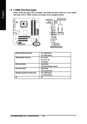
...+ HD- Pin 3: NC Pin 4: Data(-) Open: Normal Close: Reset Hardware System Open: Normal Close: Power On/Off Pin 1: LED anode(+) Pin 2: LED cathode(-) NC GA-946GM-DS2/S2 (rev. 2.0) Motherboard - 22 - of your chassis front panel to the F_PANEL connector according to the pin assignment below. English 8) F_PANEL (Front Panel Jumper) Please connect the...
...+ HD- Pin 3: NC Pin 4: Data(-) Open: Normal Close: Reset Hardware System Open: Normal Close: Power On/Off Pin 1: LED anode(+) Pin 2: LED cathode(-) NC GA-946GM-DS2/S2 (rev. 2.0) Motherboard - 22 - of your chassis front panel to the F_PANEL connector according to the pin assignment below. English 8) F_PANEL (Front Panel Jumper) Please connect the...

Manual
Page 24
Pin No. Definition 1 1 CD-L 2 GND 3 GND 4 CD-R GA-946GM-DS2/S2 (rev. 2.0) Motherboard - 24 - English 10) PWR_LED The PWR_LED connector is connected with the system power indicator to the connector. Definition 1 MPD+ 2 MPD- 3 MPD- 1 11) CD_IN (CD IN) Connect CD-ROM or DVD-ROM audio out to indicate whether the system is on/off. Pin No. It will blink when the system enters suspend mode (S1).
Pin No. Definition 1 1 CD-L 2 GND 3 GND 4 CD-R GA-946GM-DS2/S2 (rev. 2.0) Motherboard - 24 - English 10) PWR_LED The PWR_LED connector is connected with the system power indicator to the connector. Definition 1 MPD+ 2 MPD- 3 MPD- 1 11) CD_IN (CD IN) Connect CD-ROM or DVD-ROM audio out to indicate whether the system is on/off. Pin No. It will blink when the system enters suspend mode (S1).
Manual
Page 26
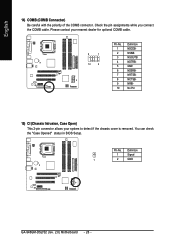
Please contact your nearest dealer for optional COMB cable. 9 1 10 2 Pin No. 1 2 3 4 5 6 7 8 9 10 Definition NDCDBNSINB NSOUTB NDTRBGND NDSRBNRTSBNCTSBNRIBNo Pin 15) CI (Chassis Intrusion, Case Open) This 2-pin connector allows your system to detect if the chassis cover is removed. You can check the "Case Opened" status in BIOS Setup. Pin No. English 14) COMB (COMB Connector) Be careful with the polarity of the COMB connector. Check the pin assignments while you connect the COMB cable. Definition 1 Signal 1 2 GND GA-946GM-DS2/S2 (rev. 2.0) Motherboard - 26 -
Please contact your nearest dealer for optional COMB cable. 9 1 10 2 Pin No. 1 2 3 4 5 6 7 8 9 10 Definition NDCDBNSINB NSOUTB NDTRBGND NDSRBNRTSBNCTSBNRIBNo Pin 15) CI (Chassis Intrusion, Case Open) This 2-pin connector allows your system to detect if the chassis cover is removed. You can check the "Case Opened" status in BIOS Setup. Pin No. English 14) COMB (COMB Connector) Be careful with the polarity of the COMB connector. Check the pin assignments while you connect the COMB cable. Definition 1 Signal 1 2 GND GA-946GM-DS2/S2 (rev. 2.0) Motherboard - 26 -
Manual
Page 28
English GA-946GM-DS2/S2 (rev. 2.0) Motherboard - 28 -
English GA-946GM-DS2/S2 (rev. 2.0) Motherboard - 28 -

Manual
Page 29
...power is turned on, pressing the button during the BIOS POST (Power-On Self Test) will take you wish to upgrade to a new BIOS, either Gigabyte's Q-Flash or @BIOS utility can enter the BIOS setup screen by pressing "Ctrl + F1". If you to quickly and easily update or backup BIOS... without entering the operating system. @BIOS is displayed at the bottom of the motherboard. CONTROL KEYS Enter> Move to Main Menu Increase the numeric value or make changes Decrease the numeric value or make changes General help window that...
...power is turned on, pressing the button during the BIOS POST (Power-On Self Test) will take you wish to upgrade to a new BIOS, either Gigabyte's Q-Flash or @BIOS utility can enter the BIOS setup screen by pressing "Ctrl + F1". If you to quickly and easily update or backup BIOS... without entering the operating system. @BIOS is displayed at the bottom of the motherboard. CONTROL KEYS Enter> Move to Main Menu Increase the numeric value or make changes Decrease the numeric value or make changes General help window that...


