
Manual
Page 1
GA-946GM-DS2/S2 (rev. 2.0) Intel® CoreTM 2 Extreme quad-core / CoreTM 2 Quad / Intel® CoreTM 2 Extreme dual-core / CoreTM 2 Duo / Intel® Pentium® Processor Extreme Edition / Intel® Pentium® D / Pentium® 4 LGA775 Processor Motherboard User's Manual Rev. 2002 12ME-946GMDR-2002R * The WEEE marking on the product indicates this product must not be...
GA-946GM-DS2/S2 (rev. 2.0) Intel® CoreTM 2 Extreme quad-core / CoreTM 2 Quad / Intel® CoreTM 2 Extreme dual-core / CoreTM 2 Duo / Intel® Pentium® Processor Extreme Edition / Intel® Pentium® D / Pentium® 4 LGA775 Processor Motherboard User's Manual Rev. 2002 12ME-946GMDR-2002R * The WEEE marking on the product indicates this product must not be...
Manual
Page 2
Motherboard GA-946GM-DS2/GA-946GM-S2 (rev. 2.0) Oct. 20, 2006 Motherboard GA-946GM-DS2/ GA-946GM-S2 (rev. 2.0) Oct. 20, 2006
Motherboard GA-946GM-DS2/GA-946GM-S2 (rev. 2.0) Oct. 20, 2006 Motherboard GA-946GM-DS2/ GA-946GM-S2 (rev. 2.0) Oct. 20, 2006
Manual
Page 4
Table of Contents ItemChecklist ...6 OptionalAccessories ...6 GA-946GM-DS2/GA-946GM-S2 (rev. 2.0) Motherboard Layout 7 Block Diagram ...8 Chapter 1 Hardware Installation 9 1-1 Considerations Prior to Installation 9 1-2 Feature Summary 10 1-3 Installation of the ...Expansion Cards 16 1-6 I/O Back Panel Introduction 17 1-7 Connectors Introduction 18 Chapter 2 BIOS Setup 29 The Main Menu (For example: BIOS Ver. : GA-946GM-DS2 F1a 30 2-1 Standard CMOS Features 32 2-2 Advanced BIOS Features 34 2-3 IntegratedPeripherals 36 2-4 Power Management Setup 39 2-5 PnP/PCI Configurations 41 2-6 ...
Table of Contents ItemChecklist ...6 OptionalAccessories ...6 GA-946GM-DS2/GA-946GM-S2 (rev. 2.0) Motherboard Layout 7 Block Diagram ...8 Chapter 1 Hardware Installation 9 1-1 Considerations Prior to Installation 9 1-2 Feature Summary 10 1-3 Installation of the ...Expansion Cards 16 1-6 I/O Back Panel Introduction 17 1-7 Connectors Introduction 18 Chapter 2 BIOS Setup 29 The Main Menu (For example: BIOS Ver. : GA-946GM-DS2 F1a 30 2-1 Standard CMOS Features 32 2-2 Advanced BIOS Features 34 2-3 IntegratedPeripherals 36 2-4 Power Management Setup 39 2-5 PnP/PCI Configurations 41 2-6 ...
Manual
Page 7
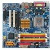
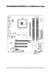
GA-946GM-DS2/GA-946GM-S2 (rev. 2.0) Motherboard Layout VGA KB_MS ATX_12V LGA775 CPU_FAN GA-946GM-DS2/GA-946GM-S2 IT8718 COMA LPT USB USB AUDIO LAN BATTERY SYS_FAN CLR_CMOS Intel® 946GZ F_AUDIO PCIE_16 RTL8111B PCI1 BIOS PCI2 CD_IN CODEC PCIE_1 REV: 2.0 SPDIF_IO FDD COMB DDRII1 DDRII2 DDRII3 DDRII4 ATX IDE SATAII2 SATAII3 Intel® ICH7 CI SATAII0 SATAII1 F_PANEL PWR_LED F_USB1 F_USB2 - 7 -
GA-946GM-DS2/GA-946GM-S2 (rev. 2.0) Motherboard Layout VGA KB_MS ATX_12V LGA775 CPU_FAN GA-946GM-DS2/GA-946GM-S2 IT8718 COMA LPT USB USB AUDIO LAN BATTERY SYS_FAN CLR_CMOS Intel® 946GZ F_AUDIO PCIE_16 RTL8111B PCI1 BIOS PCI2 CD_IN CODEC PCIE_1 REV: 2.0 SPDIF_IO FDD COMB DDRII1 DDRII2 DDRII3 DDRII4 ATX IDE SATAII2 SATAII3 Intel® ICH7 CI SATAII0 SATAII1 F_PANEL PWR_LED F_USB1 F_USB2 - 7 -

Manual
Page 10
...; 1 S/PDIF In/Out connector Š 1 COMB connector Š 2 USB 2.0/1.1 connectors for additional 4 ports by cables Š 1 power LED connector Š 1 Chassis Intrusion connector "*" Only the GA-946GM-DS2 adopts All-Solid Capacitor design. GA-946GM-DS2/S2 (rev. 2.0) Motherboard - 10 -
...; 1 S/PDIF In/Out connector Š 1 COMB connector Š 2 USB 2.0/1.1 connectors for additional 4 ports by cables Š 1 power LED connector Š 1 Chassis Intrusion connector "*" Only the GA-946GM-DS2 adopts All-Solid Capacitor design. GA-946GM-DS2/S2 (rev. 2.0) Motherboard - 10 -
Manual
Page 12
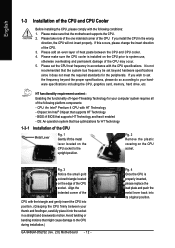
... for HT Technology 1-3-1 Installation of the CPU Metal Lever Fig. 1 Gently lift the metal lever located on the CPU prior to the CPU during installation.) GA-946GM-DS2/S2 (rev. 2.0) Motherboard - 12 - HT functionality requirement content : Enabling the functionality of Hyper-Threading Technology for the peripherals. Align the indented corner of the CPU...
... for HT Technology 1-3-1 Installation of the CPU Metal Lever Fig. 1 Gently lift the metal lever located on the CPU prior to the CPU during installation.) GA-946GM-DS2/S2 (rev. 2.0) Motherboard - 12 - HT functionality requirement content : Enabling the functionality of Hyper-Threading Technology for the peripherals. Align the indented corner of the CPU...
Manual
Page 14
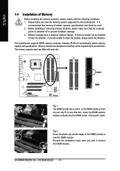
Please make sure that the computer power is switched off to lock the DIMM module. It is supported by the motherboard. Then push it down. GA-946GM-DS2/S2 (rev. 2.0) Motherboard - 14 - English 1-4 Installation of Memory Before installing the memory modules, please comply with each slot. Fig.2 Close the plastic clip at both edges of...
Please make sure that the computer power is switched off to lock the DIMM module. It is supported by the motherboard. Then push it down. GA-946GM-DS2/S2 (rev. 2.0) Motherboard - 14 - English 1-4 Installation of Memory Before installing the memory modules, please comply with each slot. Fig.2 Close the plastic clip at both edges of...

Manual
Page 16
... PCI Express x16 slot when you try to install/ uninstall the VGA card. Replace your VGA card is locked by following the steps outlined below: 1. GA-946GM-DS2/S2 (rev. 2.0) Motherboard - 16 - Please align the VGA card to the onboard PCI Express x16 slot and press firmly down on the slot. Remove your expansion...
... PCI Express x16 slot when you try to install/ uninstall the VGA card. Replace your VGA card is locked by following the steps outlined below: 1. GA-946GM-DS2/S2 (rev. 2.0) Motherboard - 16 - Please align the VGA card to the onboard PCI Express x16 slot and press firmly down on the slot. Remove your expansion...

Manual
Page 18
...) 3) CPU_FAN 4) SYS_FAN 5) FDD 6) IDE 7) SATAII0/1/2/3 8) F_PANEL 9) F_AUDIO 10) PWR_LED 11) CD_IN 12) SPDIF_IO 13) F_USB1/F_USB2 14) COMB 15) CI 16) CLR_CMOS 17) BATTERY GA-946GM-DS2/S2 (rev. 2.0) Motherboard - 18 - English In addition to the default speakers settings, the ~ audio jacks can be connected to the default Mic In jack ( ) . Please refer to...
...) 3) CPU_FAN 4) SYS_FAN 5) FDD 6) IDE 7) SATAII0/1/2/3 8) F_PANEL 9) F_AUDIO 10) PWR_LED 11) CD_IN 12) SPDIF_IO 13) F_USB1/F_USB2 14) COMB 15) CI 16) CLR_CMOS 17) BATTERY GA-946GM-DS2/S2 (rev. 2.0) Motherboard - 18 - English In addition to the default speakers settings, the ~ audio jacks can be connected to the default Mic In jack ( ) . Please refer to...
Manual
Page 20
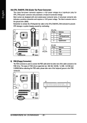
.... The black connector wire is used to connect the FDD cable while the other end of the foolproof groove in the FDD connector. 33 1 34 2 GA-946GM-DS2/S2 (rev. 2.0) Motherboard - 20 - English 3/4) CPU_FAN/SYS_FAN (Cooler Fan Power Connector) The cooler fan power connector supplies a +12V power voltage via a 3-pin/4-pin (only for CPU_FAN...
.... The black connector wire is used to connect the FDD cable while the other end of the foolproof groove in the FDD connector. 33 1 34 2 GA-946GM-DS2/S2 (rev. 2.0) Motherboard - 20 - English 3/4) CPU_FAN/SYS_FAN (Cooler Fan Power Connector) The cooler fan power connector supplies a +12V power voltage via a 3-pin/4-pin (only for CPU_FAN...
Manual
Page 22
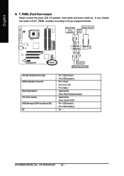
... 1: Power Pin 2- Pin 3: NC Pin 4: Data(-) Open: Normal Close: Reset Hardware System Open: Normal Close: Power On/Off Pin 1: LED anode(+) Pin 2: LED cathode(-) NC GA-946GM-DS2/S2 (rev. 2.0) Motherboard - 22 - of your chassis front panel to the F_PANEL connector according to the pin assignment below.
... 1: Power Pin 2- Pin 3: NC Pin 4: Data(-) Open: Normal Close: Reset Hardware System Open: Normal Close: Power On/Off Pin 1: LED anode(+) Pin 2: LED cathode(-) NC GA-946GM-DS2/S2 (rev. 2.0) Motherboard - 22 - of your chassis front panel to the F_PANEL connector according to the pin assignment below.

Manual
Page 24
It will blink when the system enters suspend mode (S1). Pin No. English 10) PWR_LED The PWR_LED connector is connected with the system power indicator to the connector. Definition 1 MPD+ 2 MPD- 3 MPD- 1 11) CD_IN (CD IN) Connect CD-ROM or DVD-ROM audio out to indicate whether the system is on/off. Pin No. Definition 1 1 CD-L 2 GND 3 GND 4 CD-R GA-946GM-DS2/S2 (rev. 2.0) Motherboard - 24 -
It will blink when the system enters suspend mode (S1). Pin No. English 10) PWR_LED The PWR_LED connector is connected with the system power indicator to the connector. Definition 1 MPD+ 2 MPD- 3 MPD- 1 11) CD_IN (CD IN) Connect CD-ROM or DVD-ROM audio out to indicate whether the system is on/off. Pin No. Definition 1 1 CD-L 2 GND 3 GND 4 CD-R GA-946GM-DS2/S2 (rev. 2.0) Motherboard - 24 -
Manual
Page 26
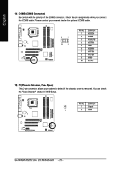
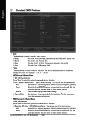
Check the pin assignments while you connect the COMB cable. Definition 1 Signal 1 2 GND GA-946GM-DS2/S2 (rev. 2.0) Motherboard - 26 - Pin No. You can check the "Case Opened" status in BIOS Setup. Please contact your nearest dealer for optional COMB cable. 9 1 10 2 Pin No. 1 2 3 4 5 6 7 8 9 10 Definition NDCDBNSINB NSOUTB NDTRBGND NDSRBNRTSBNCTSBNRIBNo Pin 15) CI (Chassis Intrusion, Case Open) This 2-pin connector allows your system to detect if the chassis cover is removed. English 14) COMB (COMB Connector) Be careful with the polarity of the COMB connector.
Check the pin assignments while you connect the COMB cable. Definition 1 Signal 1 2 GND GA-946GM-DS2/S2 (rev. 2.0) Motherboard - 26 - Pin No. You can check the "Case Opened" status in BIOS Setup. Please contact your nearest dealer for optional COMB cable. 9 1 10 2 Pin No. 1 2 3 4 5 6 7 8 9 10 Definition NDCDBNSINB NSOUTB NDTRBGND NDSRBNRTSBNCTSBNRIBNo Pin 15) CI (Chassis Intrusion, Case Open) This 2-pin connector allows your system to detect if the chassis cover is removed. English 14) COMB (COMB Connector) Be careful with the polarity of the COMB connector.

Manual
Page 28
English GA-946GM-DS2/S2 (rev. 2.0) Motherboard - 28 -
English GA-946GM-DS2/S2 (rev. 2.0) Motherboard - 28 -

Manual
Page 30
... reference only and may differ from the exact settings for your motherboard. English : Boot Menu Select boot sequence for onboard (or add-on the screen. GA-946GM-DS2/S2 (rev. 2.0) Motherboard - 30 - Award Modular BIOS v6.00PG, An Energy Star Ally Copyright (C) 1984-2006, Award Software, Inc. Boot Menu == Select a Boot First device ...CDROM ZIP USB-FDD USB-ZIP USB-CDROM USB-HDD LAN KL:Move Enter :Accept ESC:Exit The Main Menu (For example: BIOS Ver. : GA-946GM-DS2 F1a) Once you want, press "Ctrl+F1" to accept or enter the sub-menu. Use arrow keys to select among the items and ...
... reference only and may differ from the exact settings for your motherboard. English : Boot Menu Select boot sequence for onboard (or add-on the screen. GA-946GM-DS2/S2 (rev. 2.0) Motherboard - 30 - Award Modular BIOS v6.00PG, An Energy Star Ally Copyright (C) 1984-2006, Award Software, Inc. Boot Menu == Select a Boot First device ...CDROM ZIP USB-FDD USB-ZIP USB-CDROM USB-HDD LAN KL:Move Enter :Accept ESC:Exit The Main Menu (For example: BIOS Ver. : GA-946GM-DS2 F1a) Once you want, press "Ctrl+F1" to accept or enter the sub-menu. Use arrow keys to select among the items and ...
Manual
Page 32
.... IDE/SATA Device Setup. The four options are used and the system will skip the automatic detection step and allow for faster system start up . GA-946GM-DS2/S2 (rev. 2.0) Motherboard - 32 - Manual User can use one of three methods: Auto Allows BIOS to set the access mode for automatic device detection. to select...
.... IDE/SATA Device Setup. The four options are used and the system will skip the automatic detection step and allow for faster system start up . GA-946GM-DS2/S2 (rev. 2.0) Motherboard - 32 - Manual User can use one of three methods: Auto Allows BIOS to set the access mode for automatic device detection. to select...

Manual
Page 34
... hardware monitor utility is not entered at the prompt. LAN Select your boot device priority by LAN. LS120 Select your boot device priority by LS120. GA-946GM-DS2/S2 (rev. 2.0) Motherboard - 34 - Disabled Disable this function. CDROM Select your boot device priority by CDROM. Enabled Enable HDD S.M.A.R.T. Password Check Setup The system will boot...
... hardware monitor utility is not entered at the prompt. LAN Select your boot device priority by LAN. LS120 Select your boot device priority by LS120. GA-946GM-DS2/S2 (rev. 2.0) Motherboard - 34 - Disabled Disable this function. CDROM Select your boot device priority by CDROM. Enabled Enable HDD S.M.A.R.T. Password Check Setup The system will boot...

Manual
Page 36
... Help F7: Optimized Defaults On-Chip Primary PCI IDE Enabled Enable the first onboard IDE channel. (Default value) Disabled Disable the first onboard IDE channel. GA-946GM-DS2/S2 (rev. 2.0) Motherboard - 36 -
... Help F7: Optimized Defaults On-Chip Primary PCI IDE Enabled Enable the first onboard IDE channel. (Default value) Disabled Disable the first onboard IDE channel. GA-946GM-DS2/S2 (rev. 2.0) Motherboard - 36 -
Manual
Page 38
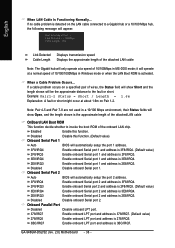
... Port 2 Auto BIOS will show Short and the length shown will operate at Port..... Note: Pair 4-5 and Pair 7-8 are not used in MS-DOS mode; GA-946GM-DS2/S2 (rev. 2.0) Motherboard - 38 - Link Detected --> 100Mbps Cable Length= 30m Link Detected Cable Length Displays transmission speed Displays the approximate length of the attached LAN cable...
... Port 2 Auto BIOS will show Short and the length shown will operate at Port..... Note: Pair 4-5 and Pair 7-8 are not used in MS-DOS mode; GA-946GM-DS2/S2 (rev. 2.0) Motherboard - 38 - Link Detected --> 100Mbps Cable Length= 30m Link Detected Cable Length Displays transmission speed Displays the approximate length of the attached LAN cable...

Manual
Page 40
... Click Disable this function. (Default value) Keyboard 98 If your keyboard has "POWER Key" button, you can press the key to power on the system. GA-946GM-DS2/S2 (rev. 2.0) Motherboard - 40 - KB Power ON Password When "Power On by Alarm is Enabled. Power On By Keyboard Password Enter from 1 to 5 characters) and press...
... Click Disable this function. (Default value) Keyboard 98 If your keyboard has "POWER Key" button, you can press the key to power on the system. GA-946GM-DS2/S2 (rev. 2.0) Motherboard - 40 - KB Power ON Password When "Power On by Alarm is Enabled. Power On By Keyboard Password Enter from 1 to 5 characters) and press...


