Manual
Page 1
GA-945PL-DS3/ GA-945PL-S3 (rev. 2.0) Intel® CoreTM 2 Extreme dual-core / CoreTM 2 Duo / Intel® Pentium® D / Pentium® 4 / Celeron® D LGA775 Processor Motherboard User's Manual Rev. 2002 12ME-945PLDS3-2002R * The WEEE marking on the product indicates this product must not be disposed of with user's other household waste and must be handed over to a designated collection point for the recycling of waste electrical and electronic equipment!! * The WEEE marking applies only in European Union's member states.
GA-945PL-DS3/ GA-945PL-S3 (rev. 2.0) Intel® CoreTM 2 Extreme dual-core / CoreTM 2 Duo / Intel® Pentium® D / Pentium® 4 / Celeron® D LGA775 Processor Motherboard User's Manual Rev. 2002 12ME-945PLDS3-2002R * The WEEE marking on the product indicates this product must not be disposed of with user's other household waste and must be handed over to a designated collection point for the recycling of waste electrical and electronic equipment!! * The WEEE marking applies only in European Union's member states.
Manual
Page 2
Motherboard GA-945PL-DS3/GA-945PL-S3 (rev. 2.0) Oct. 25, 2006 Motherboard GA-945PL-DS3/ GA-945PL-S3 (rev. 2.0) Oct. 25, 2006
Motherboard GA-945PL-DS3/GA-945PL-S3 (rev. 2.0) Oct. 25, 2006 Motherboard GA-945PL-DS3/ GA-945PL-S3 (rev. 2.0) Oct. 25, 2006
Manual
Page 4
Table of Contents ItemChecklist ...6 OptionalAccessories ...6 GA-945PL-DS3/GA-945PL-S3 (rev. 2.0) Motherboard Layout 7 Block Diagram ...8 Chapter 1 Hardware Installation 9 1-1 Considerations Prior to Installation 9 1-2 Feature Summary 10 1-3 Installation of ...Installation of Expansion Cards 16 1-6 I/O Back Panel Introduction 17 1-7 Connectors Introduction 18 Chapter 2 BIOS Setup 29 The Main Menu (For example: GA-945PL-DS3 BIOS Ver.: F1a 30 2-1 Standard CMOS Features 32 2-2 Advanced BIOS Features 34 2-3 IntegratedPeripherals 36 2-4 Power Management Setup 39 2-5 PnP/PCI Configurations...
Table of Contents ItemChecklist ...6 OptionalAccessories ...6 GA-945PL-DS3/GA-945PL-S3 (rev. 2.0) Motherboard Layout 7 Block Diagram ...8 Chapter 1 Hardware Installation 9 1-1 Considerations Prior to Installation 9 1-2 Feature Summary 10 1-3 Installation of ...Installation of Expansion Cards 16 1-6 I/O Back Panel Introduction 17 1-7 Connectors Introduction 18 Chapter 2 BIOS Setup 29 The Main Menu (For example: GA-945PL-DS3 BIOS Ver.: F1a 30 2-1 Standard CMOS Features 32 2-2 Advanced BIOS Features 34 2-3 IntegratedPeripherals 36 2-4 Power Management Setup 39 2-5 PnP/PCI Configurations...
Manual
Page 7
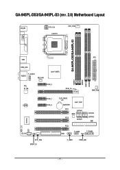
GA-945PL-DS3/GA-945PL-S3 (rev. 2.0) Motherboard Layout KB_MS ATX_12V LGA775 CPU_FAN GA-945PL-DS3/GA-945PL-S3 COMA LPT ATX USB USB_LAN F_AUDIO AUDIO NB_FAN Intel® 945PL RTL 8111B PCIE_3 PCIE_16 DDRII1 DDRII2 DDRII3 DDRII4 PWR_FAN CODEC PCIE_1 PCIE_2 CI CD_IN SYS _FAN SPDIF_IO CLR_CMOS BATTERY Intel® ICH7 PCI1 SATAII0 BIOS PCI2 SATAII1 PCI3 FDD F_USB2 SATAII2 SATAII3 IDE1 F_PANEL F_USB1 PWR_LED - 7 - REV: 2.0 IT8718
GA-945PL-DS3/GA-945PL-S3 (rev. 2.0) Motherboard Layout KB_MS ATX_12V LGA775 CPU_FAN GA-945PL-DS3/GA-945PL-S3 COMA LPT ATX USB USB_LAN F_AUDIO AUDIO NB_FAN Intel® 945PL RTL 8111B PCIE_3 PCIE_16 DDRII1 DDRII2 DDRII3 DDRII4 PWR_FAN CODEC PCIE_1 PCIE_2 CI CD_IN SYS _FAN SPDIF_IO CLR_CMOS BATTERY Intel® ICH7 PCI1 SATAII0 BIOS PCI2 SATAII1 PCI3 FDD F_USB2 SATAII2 SATAII3 IDE1 F_PANEL F_USB1 PWR_LED - 7 - REV: 2.0 IT8718
Manual
Page 9
...the conditions recommended in the user manual. 3. Thus, prior to be an unofficial Gigabyte product. - 9 - Please turn off before unplugging the power supply connector from the motherboard. Product determined to installation, please follow the instructions below: 1. Prior to installing ...to use of electrostatic discharge (ESD). English Chapter 1 Hardware Installation 1-1 Considerations Prior to Installation Preparing Your Computer The motherboard contains numerous delicate electronic circuits and components which can lead to damage to system components as well as physical harm to...
...the conditions recommended in the user manual. 3. Thus, prior to be an unofficial Gigabyte product. - 9 - Please turn off before unplugging the power supply connector from the motherboard. Product determined to installation, please follow the instructions below: 1. Prior to installing ...to use of electrostatic discharge (ESD). English Chapter 1 Hardware Installation 1-1 Considerations Prior to Installation Preparing Your Computer The motherboard contains numerous delicate electronic circuits and components which can lead to damage to system components as well as physical harm to...
Manual
Page 10
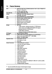
GA-945PL-(D)S3 (rev. 2.0) Motherboard - 10 - English 1-2 Feature Summary CPU Š LGA775 for Intel® CoreTM 2 Extreme dual-core / CoreTM 2 Duo / Pentium® D / Pentium® 4 / Celeron® D Š L2 cache varies with CPU Front Side Bus Š Supports 800/533 MHz FSB Chipset Northbridge: Intel® 945PL Express Chipset Š Southbridge:...PDIF In/Out connector Š 2 USB 2.0/1.1 connectors for additional 4 USB 2.0/1.1 ports by cables Š 1 power LED connector Š 1 Chassis Intrusion connector "*" Only the GA-945PL-DS3 adopts All-Solid Capacitor design.
GA-945PL-(D)S3 (rev. 2.0) Motherboard - 10 - English 1-2 Feature Summary CPU Š LGA775 for Intel® CoreTM 2 Extreme dual-core / CoreTM 2 Duo / Pentium® D / Pentium® 4 / Celeron® D Š L2 cache varies with CPU Front Side Bus Š Supports 800/533 MHz FSB Chipset Northbridge: Intel® 945PL Express Chipset Š Southbridge:...PDIF In/Out connector Š 2 USB 2.0/1.1 connectors for additional 4 USB 2.0/1.1 ports by cables Š 1 power LED connector Š 1 Chassis Intrusion connector "*" Only the GA-945PL-DS3 adopts All-Solid Capacitor design.
Manual
Page 11
... reduced from 533 MHz down to 400 MHz. (Please refer to to Page 15 for more information.) (Note 2) EasyTune functions may vary depending on different motherboards. - 11 -
... reduced from 533 MHz down to 400 MHz. (Please refer to to Page 15 for more information.) (Note 2) EasyTune functions may vary depending on different motherboards. - 11 -
Manual
Page 12
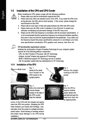
... the plastic covering on the edge of the CPU. Fig. 4 Once the CPU is installed on the CPU socket to the CPU during installation.) GA-945PL-(D)S3 (rev. 2.0) Motherboard - 12 - HT functionality requirement content : Enabling the functionality of Hyper-Threading Technology for HT Technology 1-3-1 Installation of the CPU Metal Lever Fig. 1 Gently lift...
... the plastic covering on the edge of the CPU. Fig. 4 Once the CPU is installed on the CPU socket to the CPU during installation.) GA-945PL-(D)S3 (rev. 2.0) Motherboard - 12 - HT functionality requirement content : Enabling the functionality of Hyper-Threading Technology for HT Technology 1-3-1 Installation of the CPU Metal Lever Fig. 1 Gently lift...
Manual
Page 13
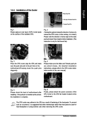
... extreme care when removing the CPU cooler. - 13 - The CPU cooler may adhere to install.) Please note the direction of arrow sign on the motherboard.Pressing down the push pins diagonally. To prevent such an occurrence, it is inserted as a result of hardening of the heat paste. Fig. 6 ...please attach the power connector of the CPU cooler to the CPU cooler installation section of the user manual) Fig. 5 Please check the back of motherboard after installing. Fig. 4 Please make sure the push pins aim to the pin hole on the male push pin doesn't face inwards before installation...
... extreme care when removing the CPU cooler. - 13 - The CPU cooler may adhere to install.) Please note the direction of arrow sign on the motherboard.Pressing down the push pins diagonally. To prevent such an occurrence, it is inserted as a result of hardening of the heat paste. Fig. 6 ...please attach the power connector of the CPU cooler to the CPU cooler installation section of the user manual) Fig. 5 Please check the back of motherboard after installing. Fig. 4 Please make sure the push pins aim to the pin hole on the male push pin doesn't face inwards before installation...
Manual
Page 14
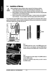
...off to remove the DIMM module. Insert the DIMM memory module vertically into the DIMM socket. It is supported by the motherboard. Before installing or removing memory modules, please make sure that the memory used is recommended that memory of similar capacity, ... only fit in one direction. The motherboard supports DDRII memory modules, whereby BIOS will automatically detect memory capacity and specifications. Fig.2 Close the plastic clip at both edges of Memory Before installing the memory modules, please comply with each slot. GA-945PL-(D)S3 (rev. 2.0) Motherboard - 14 -
...off to remove the DIMM module. Insert the DIMM memory module vertically into the DIMM socket. It is supported by the motherboard. Before installing or removing memory modules, please make sure that the memory used is recommended that memory of similar capacity, ... only fit in one direction. The motherboard supports DDRII memory modules, whereby BIOS will automatically detect memory capacity and specifications. Fig.2 Close the plastic clip at both edges of Memory Before installing the memory modules, please comply with each slot. GA-945PL-(D)S3 (rev. 2.0) Motherboard - 14 -
Manual
Page 16
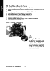
Remove your computer's chassis cover. 7. Power on the card are indeed seated in motherboard. 4. When you try uninstall the VGA card, please gently press the latch as the picture to the left shows to the onboard PCI Express x16 ... expansion slot in the slot. 5. Install related driver from BIOS. 8. Replace the screw to secure the slot bracket of expansion card from the operating system. GA-945PL-(D)S3 (rev. 2.0) Motherboard - 16 - Press the expansion card firmly into the computer. 2.
Remove your computer's chassis cover. 7. Power on the card are indeed seated in motherboard. 4. When you try uninstall the VGA card, please gently press the latch as the picture to the left shows to the onboard PCI Express x16 ... expansion slot in the slot. 5. Install related driver from BIOS. 8. Replace the screw to secure the slot bracket of expansion card from the operating system. GA-945PL-(D)S3 (rev. 2.0) Motherboard - 16 - Press the expansion card firmly into the computer. 2.
Manual
Page 18
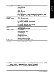
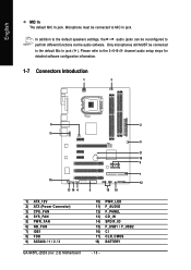
... configuration information. 1-7 Connectors Introduction 1 3 6 2 11 5 17 18 9 7 16 12 13 14 4 8 15 10 1) ATX_12V 2) ATX (Power Connector) 3) CPU_FAN 4) SYS_FAN 5) PWR_FAN 6) NB_FAN 7) IDE1 8) FDD 9) SATAII0 / 1 / 2 / 3 GA-945PL-(D)S3 (rev. 2.0) Motherboard 10) PWR_LED 11) F_AUDIO 12) F_PANEL 13) CD_IN 14) SPDIF_IO 15) F_USB1 / F_USB2 16) CI 17) CLR_CMOS 18) BATTERY - 18 - Please refer to MIC...
... configuration information. 1-7 Connectors Introduction 1 3 6 2 11 5 17 18 9 7 16 12 13 14 4 8 15 10 1) ATX_12V 2) ATX (Power Connector) 3) CPU_FAN 4) SYS_FAN 5) PWR_FAN 6) NB_FAN 7) IDE1 8) FDD 9) SATAII0 / 1 / 2 / 3 GA-945PL-(D)S3 (rev. 2.0) Motherboard 10) PWR_LED 11) F_AUDIO 12) F_PANEL 13) CD_IN 14) SPDIF_IO 15) F_USB1 / F_USB2 16) CI 17) CLR_CMOS 18) BATTERY - 18 - Please refer to MIC...
Manual
Page 19
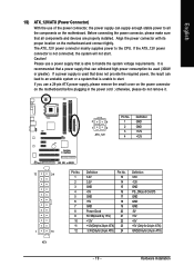
...to the CPU. If a power supply is not connected, the system will not start . Align the power connector with its proper location on the motherboard before plugging in the power cord ; Caution! If the ATX_12V power connector is used (300W or greater). otherwise, please do not remove it. ... that a power supply that is able to handle the system voltage requirements. Please use a power supply that all the components on the motherboard. Hardware Installation Before connecting the power connector, please make sure that is unable to start . If you use a 24-pin ATX power...
...to the CPU. If a power supply is not connected, the system will not start . Align the power connector with its proper location on the motherboard before plugging in the power cord ; Caution! If the ATX_12V power connector is used (300W or greater). otherwise, please do not remove it. ... that a power supply that is able to handle the system voltage requirements. Please use a power supply that all the components on the motherboard. Hardware Installation Before connecting the power connector, please make sure that is unable to start . If you use a 24-pin ATX power...
Manual
Page 20
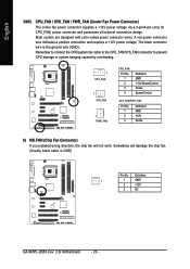
..., the chip fan will damage the chip fan. (Usually black cable is the ground wire (GND). Sometimes will not work. Definition 1 1 GND 2 +12V 3 NC GA-945PL-(D)S3 (rev. 2.0) Motherboard - 20 - The black connector wire is GND) Pin No. A red power connector wire indicates a positive connection and requires a +12V power voltage. Most coolers are...
..., the chip fan will damage the chip fan. (Usually black cable is the ground wire (GND). Sometimes will not work. Definition 1 1 GND 2 +12V 3 NC GA-945PL-(D)S3 (rev. 2.0) Motherboard - 20 - The black connector wire is GND) Pin No. A red power connector wire indicates a positive connection and requires a +12V power voltage. Most coolers are...
Manual
Page 22
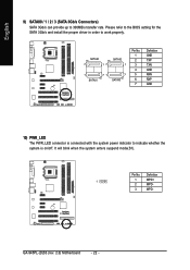
...- 3 MPD- English 9) SATAII0 / 1 / 2 / 3 (SATA 3Gb/s Connectors) SATA 3Gb/s can provide up to 300MB/s transfer rate. It will blink when the system enters suspend mode(S1). GA-945PL-(D)S3 (rev. 2.0) Motherboard - 22 -
...- 3 MPD- English 9) SATAII0 / 1 / 2 / 3 (SATA 3Gb/s Connectors) SATA 3Gb/s can provide up to 300MB/s transfer rate. It will blink when the system enters suspend mode(S1). GA-945PL-(D)S3 (rev. 2.0) Motherboard - 22 -
Manual
Page 24
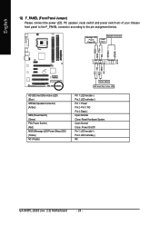
Pin 3: NC Pin 4: Data(-) Open: Normal Close: Reset Hardware System Open: Normal Close: Power On/Off Pin 1: LED anode(+) Pin 2: LED cathode(-) NC GA-945PL-(D)S3 (rev. 2.0) Motherboard - 24 - RESRES+ NC HD (IDE Hard Disk Active LED) (Blue) SPEAK (Speaker Connector) (Amber) RES (Reset Switch) (Green) PW (Power Switch) (Red) MSG (Message LED/...
Pin 3: NC Pin 4: Data(-) Open: Normal Close: Reset Hardware System Open: Normal Close: Power On/Off Pin 1: LED anode(+) Pin 2: LED cathode(-) NC GA-945PL-(D)S3 (rev. 2.0) Motherboard - 24 - RESRES+ NC HD (IDE Hard Disk Active LED) (Blue) SPEAK (Speaker Connector) (Amber) RES (Reset Switch) (Green) PW (Power Switch) (Red) MSG (Message LED/...
Manual
Page 26
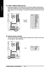
... No Pin NC 16) CI (Chassis Intrusion, Case Open) This 2-pin connector allows your system to work or even damage it. Definition 1 1 Signal 2 GND GA-945PL-(D)S3 (rev. 2.0) Motherboard - 26 - Check the pin assignment carefully while you connect the front USB cable, incorrect connection between the cable and connector will make the device...
... No Pin NC 16) CI (Chassis Intrusion, Case Open) This 2-pin connector allows your system to work or even damage it. Definition 1 1 Signal 2 GND GA-945PL-(D)S3 (rev. 2.0) Motherboard - 26 - Check the pin assignment carefully while you connect the front USB cable, incorrect connection between the cable and connector will make the device...
Manual
Page 28
English GA-945PL-(D)S3 (rev. 2.0) Motherboard - 28 -
English GA-945PL-(D)S3 (rev. 2.0) Motherboard - 28 -
Manual
Page 29
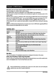
...pop up a small help window that describes the appropriate keys to use and the possible selections for Main Menu Main Menu The on the motherboard supplies the necessary power to Main Menu Increase the numeric value or make changes Decrease the numeric value or make changes General help, only... the battery on -line description of the screen. Exit current page and return to the CMOS SRAM. BIOS Setup If you to a new BIOS, either Gigabyte's Q-Flash or @BIOS utility can enter the BIOS setup screen by pressing "Ctrl + F1". The CMOS SETUP saves the configuration in system malfunction. - ...
...pop up a small help window that describes the appropriate keys to use and the possible selections for Main Menu Main Menu The on the motherboard supplies the necessary power to Main Menu Increase the numeric value or make changes Decrease the numeric value or make changes General help, only... the battery on -line description of the screen. Exit current page and return to the CMOS SRAM. BIOS Setup If you to a new BIOS, either Gigabyte's Q-Flash or @BIOS utility can enter the BIOS setup screen by pressing "Ctrl + F1". The CMOS SETUP saves the configuration in system malfunction. - ...
Manual
Page 30
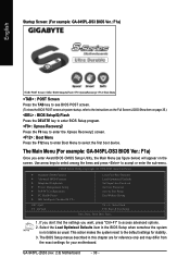
... to enter the Xpress Recovery2 screen. : Boot Menu Press the F12 key to enter Boot Menu to the default settings for your motherboard. GA-945PL-(D)S3 (rev. 2.0) Motherboard - 30 - Startup Screen: (For example: GA-945PL-DS3 BIOS Ver.: F1a) English :POST Screen :BIOS Setup/Q-Flash :XpressRecovery2 :Boot Menu : POST Screen Press the TAB key to see ... Exit Without Saving ESC: Quit F8: Q-Flash KLJI: Select Item F10: Save & Exit Setup Time, Date, Hard Disk Type... 1. The Main Menu (For example: GA-945PL-DS3 BIOS Ver.: F1a) Once you want, press "Ctrl+F1" to accept or enter the sub-menu.
... to enter the Xpress Recovery2 screen. : Boot Menu Press the F12 key to enter Boot Menu to the default settings for your motherboard. GA-945PL-(D)S3 (rev. 2.0) Motherboard - 30 - Startup Screen: (For example: GA-945PL-DS3 BIOS Ver.: F1a) English :POST Screen :BIOS Setup/Q-Flash :XpressRecovery2 :Boot Menu : POST Screen Press the TAB key to see ... Exit Without Saving ESC: Quit F8: Q-Flash KLJI: Select Item F10: Save & Exit Setup Time, Date, Hard Disk Type... 1. The Main Menu (For example: GA-945PL-DS3 BIOS Ver.: F1a) Once you want, press "Ctrl+F1" to accept or enter the sub-menu.


