Manual
Page 1
GA-8N-SLI Royal/ GA-8N-SLI Pro/ GA-8N-SLI Intel® Pentium® Processor Extreme Edition Intel® Pentium® D / Pentium® 4 LGA775 Processor Motherboard User's Manual Rev. 1004 12ME-8NSLIRO-1004
GA-8N-SLI Royal/ GA-8N-SLI Pro/ GA-8N-SLI Intel® Pentium® Processor Extreme Edition Intel® Pentium® D / Pentium® 4 LGA775 Processor Motherboard User's Manual Rev. 1004 12ME-8NSLIRO-1004
Manual
Page 4
Motherboard GA-8N-SLI Oct. 26, 2005 Motherboard GA-8N-SLI Oct. 26, 2005
Motherboard GA-8N-SLI Oct. 26, 2005 Motherboard GA-8N-SLI Oct. 26, 2005
Manual
Page 6
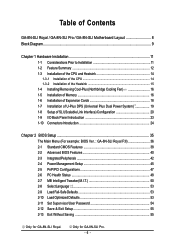
Table of Contents GA-8N-SLI Royal / GA-8N-SLI Pro / GA-8N-SLI Motherboard Layout 8 Block Diagram ...9 Chapter 1 Hardware Installation 11 1-1 Considerations Prior to Installation 11 1-2 Feature Summary 12 1-3 Installation of the CPU and ... Interface) Configuration 20 1-9 I/O Back Panel Introduction 23 1-10 Connectors Introduction 24 Chapter 2 BIOS Setup 35 The Main Menu (For example: BIOS Ver. : GA-8N-SLI Royal F3l 36 2-1 Standard CMOS Features 38 2-2 Advanced BIOS Features 40 2-3 IntegratedPeripherals 42 2-4 Power Management Setup 45 2-5 PnP/PCI Configurations 47 2-6 PC Health...
Table of Contents GA-8N-SLI Royal / GA-8N-SLI Pro / GA-8N-SLI Motherboard Layout 8 Block Diagram ...9 Chapter 1 Hardware Installation 11 1-1 Considerations Prior to Installation 11 1-2 Feature Summary 12 1-3 Installation of the CPU and ... Interface) Configuration 20 1-9 I/O Back Panel Introduction 23 1-10 Connectors Introduction 24 Chapter 2 BIOS Setup 35 The Main Menu (For example: BIOS Ver. : GA-8N-SLI Royal F3l 36 2-1 Standard CMOS Features 38 2-2 Advanced BIOS Features 40 2-3 IntegratedPeripherals 42 2-4 Power Management Setup 45 2-5 PnP/PCI Configurations 47 2-6 PC Health...
Manual
Page 8
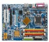
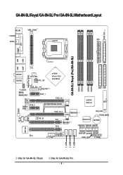
GA-8N-SLI Royal / GA-8N-SLI Pro / GA-8N-SLI Motherboard Layout KB_MS VRM_CONN COAXIAL ATX SPDIF_O LGA775 PWR_FAN COMA LPT GA-8N-SLI Royal (Pro)/GA-8N-SLI DDRII1 DDRII2 DDRII3 DDRII4 LAN1 LAN2 USB FDD USB Marvell Phy (LAN2) AUDIO1 AUDIO2 CPU_FAN ATX_12V nVIDIA® nForce 4 SLI Intel Edition F_AUDIO Marvell 8053 (LAN1) PCIE_12V Main BIOS Backup PCIE_2 BIOS NB_FAN PCIE_1 PCIE_16_1 SLI Switch Module...
GA-8N-SLI Royal / GA-8N-SLI Pro / GA-8N-SLI Motherboard Layout KB_MS VRM_CONN COAXIAL ATX SPDIF_O LGA775 PWR_FAN COMA LPT GA-8N-SLI Royal (Pro)/GA-8N-SLI DDRII1 DDRII2 DDRII3 DDRII4 LAN1 LAN2 USB FDD USB Marvell Phy (LAN2) AUDIO1 AUDIO2 CPU_FAN ATX_12V nVIDIA® nForce 4 SLI Intel Edition F_AUDIO Marvell 8053 (LAN1) PCIE_12V Main BIOS Backup PCIE_2 BIOS NB_FAN PCIE_1 PCIE_16_1 SLI Switch Module...
Manual
Page 9
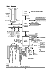
Only for GA-8N-SLI Royal. Block Diagram 1 PCIE x 16 2 PCIE x 8 PCI-ECLK (100MHz) or LGA775 Processor CPUCLK+/-(1066/800/533MHz) Host Interface DDRII 667/533MHz DIMM Normal Mode SLI Mode Switch PCI Express x 16 Bus PCI Express Bus x1 x1 x1 nVIDIA® nForce 4 SLI Intel Edition Dual Channel Memory NBCLK (25MHz) HCLK+/- (133/200... Channel 3 IEEE1394b Surround Speaker Out Center/Subwoofer Speaker Out Side Speaker Out MIC Line-Out Line-In SPDIF In SPDIF Out PCICLK (33MHz) Only for GA-8N-SLI Pro. - 9 -
Only for GA-8N-SLI Royal. Block Diagram 1 PCIE x 16 2 PCIE x 8 PCI-ECLK (100MHz) or LGA775 Processor CPUCLK+/-(1066/800/533MHz) Host Interface DDRII 667/533MHz DIMM Normal Mode SLI Mode Switch PCI Express x 16 Bus PCI Express Bus x1 x1 x1 nVIDIA® nForce 4 SLI Intel Edition Dual Channel Memory NBCLK (25MHz) HCLK+/- (133/200... Channel 3 IEEE1394b Surround Speaker Out Center/Subwoofer Speaker Out Side Speaker Out MIC Line-Out Line-In SPDIF In SPDIF Out PCICLK (33MHz) Only for GA-8N-SLI Pro. - 9 -
Manual
Page 12
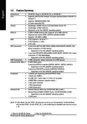
... Connections Š Š FDD Connections Š Onboard SATA 3Gb/s Š Peripherals Š Š Š Š Š Š Š Onboard LAN Š Š Š GA-8N-SLI Royal or GA-8N-SLI Pro or GA-8N-SLI Supports LGA775 Intel® Pentium® Processor Extreme Edition/ Pentium® D / Pentium® 4 Supports 1066/800/533MHz FSB L2 cache varies with CPU...
... Connections Š Š FDD Connections Š Onboard SATA 3Gb/s Š Peripherals Š Š Š Š Š Š Š Onboard LAN Š Š Š GA-8N-SLI Royal or GA-8N-SLI Pro or GA-8N-SLI Supports LGA775 Intel® Pentium® Processor Extreme Edition/ Pentium® D / Pentium® 4 Supports 1066/800/533MHz FSB L2 cache varies with CPU...
Manual
Page 13
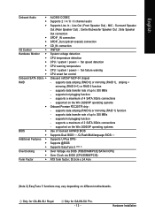
MIC ; supports a maximum of up to 300 MB/s - supports hot plugging function - Only for GA-8N-SLI Pro. - 13 - Only for GA-8N-SLI Royal. Surround Speaker Out (Rear Speaker Out) ; Side Speaker Out connection SPDIF_IN connection SPDIF_Out (optical+coaxial) connection CD_IN connection IT8712F System voltage detection CPU temperature ...
MIC ; supports a maximum of up to 300 MB/s - supports hot plugging function - Only for GA-8N-SLI Pro. - 13 - Only for GA-8N-SLI Royal. Surround Speaker Out (Rear Speaker Out) ; Side Speaker Out connection SPDIF_IN connection SPDIF_Out (optical+coaxial) connection CD_IN connection IT8712F System voltage detection CPU temperature ...
Manual
Page 14
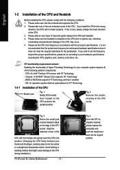
... Technology 1-3-1 Installation of the CPU Metal Lever Fig. 1 Gently lift the metal lever located on the CPU prior to the CPU during installation.) P4 nForce4 SLI Series Motherboard - 14 - CPU: An Intel® Pentium 4 Processor with the following platform components: - Please add an even layer of heat sink paste between your...
... Technology 1-3-1 Installation of the CPU Metal Lever Fig. 1 Gently lift the metal lever located on the CPU prior to the CPU during installation.) P4 nForce4 SLI Series Motherboard - 14 - CPU: An Intel® Pentium 4 Processor with the following platform components: - Please add an even layer of heat sink paste between your...
Manual
Page 16
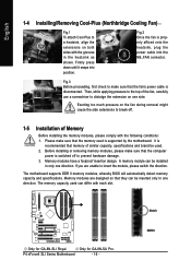
...modules, whereby BIOS will automatically detect memory capacity and specifications. Memory modules are unable to insert the module, please switch the direction. Only for GA-8N-SLI Royal. Firmly press down until it snaps into the NB_FAN connector. Exerting too much pressure on the fan during removal might cause the side ... Before installing the memory modules, please comply with the grooves in only one side. A memory module can differ with each slot. Only for GA-8N-SLI Pro. Fig.2 Once the fan is properly affixed onto the heatsink, plug the power cable into position.
...modules, whereby BIOS will automatically detect memory capacity and specifications. Memory modules are unable to insert the module, please switch the direction. Only for GA-8N-SLI Royal. Firmly press down until it snaps into the NB_FAN connector. Exerting too much pressure on the fan during removal might cause the side ... Before installing the memory modules, please comply with the grooves in only one side. A memory module can differ with each slot. Only for GA-8N-SLI Pro. Fig.2 Once the fan is properly affixed onto the heatsink, plug the power cable into position.
Manual
Page 17
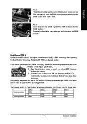
Fig.2 Close the plastic clip at both edges of Memory Bus will double. Dual Channel DDR II GA-8N-SLI Royal/GA-8N-SLI Pro/GA-8N-SLI supports the Dual Channel Technology. To enable Dual Channel mode with 2 or 4 memory modules, it down. Dual channel memory cannot be used if one direction. ...
Fig.2 Close the plastic clip at both edges of Memory Bus will double. Dual Channel DDR II GA-8N-SLI Royal/GA-8N-SLI Pro/GA-8N-SLI supports the Dual Channel Technology. To enable Dual Channel mode with 2 or 4 memory modules, it down. Dual channel memory cannot be used if one direction. ...

Manual
Page 18
Replace the screw to secure the slot bracket of the PCI Express x 16 slot when you try to install/ uninstall the VGA card. P4 nForce4 SLI Series Motherboard The PCIE_12V power connector supplies extra power to the onboard PCI Express x 16 slot and press firmly down on the card are indeed ...
Replace the screw to secure the slot bracket of the PCI Express x 16 slot when you try to install/ uninstall the VGA card. P4 nForce4 SLI Series Motherboard The PCIE_12V power connector supplies extra power to the onboard PCI Express x 16 slot and press firmly down on the card are indeed ...
Manual
Page 19
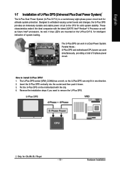
... well, 4 blue LED's are mounted on the motherbard with the latest LGA775 Intel® Pentium® 4 Processor as well as future Intel® processors. for GA-8N-SLI Royal. - 19 - Insert the U-Plus DPS vertically into the socket and then push it the ideal companion with the clip. 4. The U-Plus DPS socket (VRM_CONN...
... well, 4 blue LED's are mounted on the motherbard with the latest LGA775 Intel® Pentium® 4 Processor as well as future Intel® processors. for GA-8N-SLI Royal. - 19 - Insert the U-Plus DPS vertically into the socket and then push it the ideal companion with the clip. 4. The U-Plus DPS socket (VRM_CONN...
Manual
Page 20
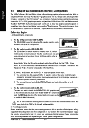
... module from the motherboard because in the SLI switch module socket by factory default. This SLI switch module has gold edge connectors on the GA-8N-SLI Royal/GA-8N-SLI Pro/GA-8N-SLI motherboard. One is Normal mode. You can install two SLI-capable PCIE x 16 graphics cards of the same model (Example: GIGABYTE GV-NX66T128D) and link them as two...
... module from the motherboard because in the SLI switch module socket by factory default. This SLI switch module has gold edge connectors on the GA-8N-SLI Royal/GA-8N-SLI Pro/GA-8N-SLI motherboard. One is Normal mode. You can install two SLI-capable PCIE x 16 graphics cards of the same model (Example: GIGABYTE GV-NX66T128D) and link them as two...
Manual
Page 21
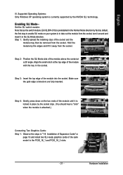
... are fully inserted. Supported Operating Systems: Only Windows XP operating system is attached.) Connecting Two Graphics Cards: Step 1: Observe the steps in the SLI Mode direction. Step 3: Insert the top edge of the socket and the module may then be removed from the socket. Step 4: Gently press ... edges and lift it in "1-6 Installation of the module with the key in the Normal Mode direction by the NVIDIA SLI technology. Enabling SLI Mode-- Step 2: Position the SLI Mode side of the module above the socket at the top edge of Expansion Cards" on your system is preinstalled in...
... are fully inserted. Supported Operating Systems: Only Windows XP operating system is attached.) Connecting Two Graphics Cards: Step 1: Observe the steps in the SLI Mode direction. Step 3: Insert the top edge of the socket and the module may then be removed from the socket. Step 4: Gently press ... edges and lift it in "1-6 Installation of the module with the key in the Normal Mode direction by the NVIDIA SLI technology. Enabling SLI Mode-- Step 2: Position the SLI Mode side of the module above the socket at the top edge of Expansion Cards" on your system is preinstalled in...
Manual
Page 22
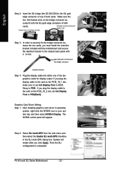
... and secure the retention bracket to the chassis back panel with a screw. Then the SLI configuration is completed. Step 2: Select SLI multi-GPU from the side menu and then select the Enable SLI multi-GPU checkbox in your system tray and then select NVIDIA Display. P4 nForce4...you click Apply. Graphics Card Driver Setting: Step 1: After installing graphics card driver in operating system, right-click the NVIDIA icon in the SLI multi-GPU dialog box. System will appear. retention bracket Step 4: Plug the display cable into either one of the bridge connector. English Step ...
... and secure the retention bracket to the chassis back panel with a screw. Then the SLI configuration is completed. Step 2: Select SLI multi-GPU from the side menu and then select the Enable SLI multi-GPU checkbox in your system tray and then select NVIDIA Display. P4 nForce4...you click Apply. Graphics Card Driver Setting: Step 1: After installing graphics card driver in operating system, right-click the NVIDIA icon in the SLI multi-GPU dialog box. System will appear. retention bracket Step 4: Plug the display cable into either one of the bridge connector. English Step ...
Manual
Page 23
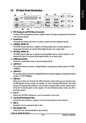
.../100/ 1000Mbps. If your OS or device(s) vendors. For more information please contact your OS does not support USB controller, please contact OS vendor for GA-8N-SLI Royal. - 23 - Line Out (Front Speaker Out) Connect the stereo speakers, earphone or front surround speakers to the lower port (purple). LAN Port 1 The provided...
.../100/ 1000Mbps. If your OS or device(s) vendors. For more information please contact your OS does not support USB controller, please contact OS vendor for GA-8N-SLI Royal. - 23 - Line Out (Front Speaker Out) Connect the stereo speakers, earphone or front surround speakers to the lower port (purple). LAN Port 1 The provided...
Manual
Page 24
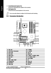
... / F_USB2/F_USB3 17) F1_1394/F2_1394 18) CLR_CMOS 19) CI 20) PCIE_12V 21) BATTERY 22) RF_ID Only for GA-8N-SLI Pro. Only for GA-8N-SLI Royal. Side Speaker Out Connect the side surround speakers to this connector. P4 nForce4 SLI Series Motherboard - 24 - English Center/Subwoofer Speaker Out Connect the Center/Subwoofer speakers to this connector.
... / F_USB2/F_USB3 17) F1_1394/F2_1394 18) CLR_CMOS 19) CI 20) PCIE_12V 21) BATTERY 22) RF_ID Only for GA-8N-SLI Pro. Only for GA-8N-SLI Royal. Side Speaker Out Connect the side surround speakers to this connector. P4 nForce4 SLI Series Motherboard - 24 - English Center/Subwoofer Speaker Out Connect the Center/Subwoofer speakers to this connector.
Manual
Page 26
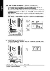
... SYS_FAN/ PWR_FAN (Cooler Fan Power Connector) The cooler fan power connector supplies a +12V power voltage via a 3-pin/4-pin (only for GA-8N-SLI Pro. Most coolers are designed with color-coded power connector wires. Please remember to connect the power to the cooler to prevent CPU overheating ...and failure. 1 CPU_FAN 1 SYS_FAN 1 PWR_FAN Pin No. 1 2 3 4 Definition GND +12V Sense Speed Control (Only for GA-8N-SLI Royal. Only for CPU_FAN)power connector and possesses a foolproof connection design. Please remember to connect the power to the CPU fan to prevent system ...
... SYS_FAN/ PWR_FAN (Cooler Fan Power Connector) The cooler fan power connector supplies a +12V power voltage via a 3-pin/4-pin (only for GA-8N-SLI Pro. Most coolers are designed with color-coded power connector wires. Please remember to connect the power to the cooler to prevent CPU overheating ...and failure. 1 CPU_FAN 1 SYS_FAN 1 PWR_FAN Pin No. 1 2 3 4 Definition GND +12V Sense Speed Control (Only for GA-8N-SLI Royal. Only for CPU_FAN)power connector and possesses a foolproof connection design. Please remember to connect the power to the CPU fan to prevent system ...
Manual
Page 27
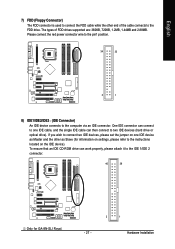
... IDE device connects to the FDD drive. To ensure that an IDE CD-ROM drive can then connect to one IDE device as Slave (for GA-8N-SLI Royal. - 27 - 2 1 Hardware Installation One IDE connector can connect to two IDE devices (hard drive or optical drive). The types of the cable connects to...
... IDE device connects to the FDD drive. To ensure that an IDE CD-ROM drive can then connect to one IDE device as Slave (for GA-8N-SLI Royal. - 27 - 2 1 Hardware Installation One IDE connector can connect to two IDE devices (hard drive or optical drive). The types of the cable connects to...
Manual
Page 28
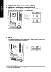
...) PWR_LED PWR_LED is connected with the system power indicator to 300MB/s transfer rate. P4 nForce4 SLI Series Motherboard - 28 - Only for the SATA 3Gb/s and install the proper driver in order to the BIOS setting for GA-8N-SLI Royal. Please refer to work properly. Definition 1 MPD+ 2 MPD- 3 MPD- Pin No. It will blink...
...) PWR_LED PWR_LED is connected with the system power indicator to 300MB/s transfer rate. P4 nForce4 SLI Series Motherboard - 28 - Only for the SATA 3Gb/s and install the proper driver in order to the BIOS setting for GA-8N-SLI Royal. Please refer to work properly. Definition 1 MPD+ 2 MPD- 3 MPD- Pin No. It will blink...


