
Manual
Page 4
...Contents GA-8I945PLGE-RH Motherboard Layout 6 Block Diagram ...7 Chapter 1 Hardware Installation 9 1-1 Considerations Prior to Installation 9 1-2 Feature Summary 10 1-3 Installation of the CPU and Heatsink 12 1-3-1 Installation of the CPU 12 1-3-2 Installation of the Heatsink 13 1-4 Installation of Memory 14 1-5 Installation of Expansion Cards 16 1-6 I/O Back Panel Introduction 17 1-7 Connectors Introduction 18 Chapter 2 BIOS Setup 29 The Main Menu (For example: BIOS Ver. : F1a 30 2-1 Standard CMOS Features 32 2-2 Advanced BIOS Features 34 2-3 IntegratedPeripherals 36 2-4 Power...
...Contents GA-8I945PLGE-RH Motherboard Layout 6 Block Diagram ...7 Chapter 1 Hardware Installation 9 1-1 Considerations Prior to Installation 9 1-2 Feature Summary 10 1-3 Installation of the CPU and Heatsink 12 1-3-1 Installation of the CPU 12 1-3-2 Installation of the Heatsink 13 1-4 Installation of Memory 14 1-5 Installation of Expansion Cards 16 1-6 I/O Back Panel Introduction 17 1-7 Connectors Introduction 18 Chapter 2 BIOS Setup 29 The Main Menu (For example: BIOS Ver. : F1a 30 2-1 Standard CMOS Features 32 2-2 Advanced BIOS Features 34 2-3 IntegratedPeripherals 36 2-4 Power...

Manual
Page 10
...to 2GB memory) Š Supports dual channel DDR II 533/400 unbuffered DIMMs Š Supports 1.8V DDR II DIMMs Expanstion Slots Š 1 PCI Express x 16 slot Š 2 PCI Express x 1 slots Š 3 PCI slots Internal Connectors Š 1 24-pin ATX power connector Š 1 4-pin ATX 12V power connector Š 1 floppy connector Š 1 IDE connector Š 4 SATA 3Gb/s connectors Š 1 CPU fan connector Š 1 system fan connector Š 1 front panel connector Š 1 front audio connector Š 1 CD In connector Š 1 SPDIF In connector Š 1 power LED connector...
...to 2GB memory) Š Supports dual channel DDR II 533/400 unbuffered DIMMs Š Supports 1.8V DDR II DIMMs Expanstion Slots Š 1 PCI Express x 16 slot Š 2 PCI Express x 1 slots Š 3 PCI slots Internal Connectors Š 1 24-pin ATX power connector Š 1 4-pin ATX 12V power connector Š 1 floppy connector Š 1 IDE connector Š 4 SATA 3Gb/s connectors Š 1 CPU fan connector Š 1 system fan connector Š 1 front panel connector Š 1 front audio connector Š 1 CD In connector Š 1 SPDIF In connector Š 1 power LED connector...

Manual
Page 15
English Dual Channel Memory Configuration The GA-8I945PLGE-RH supports the Dual Channel Technology. Dual Channel mode will add double. The GA-8I945PLGE-RH includes 2 DIMM sockets. To enable Dual Channel mode, please insert two DDR II memory modules (it is installed. 2. If you want to operate the Dual Channel Technology, please note the following explanations due to use memory modules of Intel chipset specifications. 1. After operating the Dual Channel Technology, the bandwidth of Memory Bus will not be enabled if only one DDR II memory module is recommended...
English Dual Channel Memory Configuration The GA-8I945PLGE-RH supports the Dual Channel Technology. Dual Channel mode will add double. The GA-8I945PLGE-RH includes 2 DIMM sockets. To enable Dual Channel mode, please insert two DDR II memory modules (it is installed. 2. If you want to operate the Dual Channel Technology, please note the following explanations due to use memory modules of Intel chipset specifications. 1. After operating the Dual Channel Technology, the bandwidth of Memory Bus will not be enabled if only one DDR II memory module is recommended...
Manual
Page 18
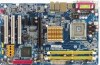
.... channel audio setup steps for detailed software configuration information. 1-7 Connectors Introduction 1 3 8 2 4 11 16 17 6 15 10 12 14 5 13 7 9 1) ATX_12V 10) F_PANEL 2) ATX (Power Connector) 11) CD_IN 3) CPU_FAN 12) SPDIF_I 4) SYS_FAN 13) F_USB1/F_USB2 5) FDD 14) RF_ID 6) IDE1 15) CI 7) SATAII0 / SATAII1 / SATAII2 / SATAII3 16) CLR_CMOS 8) F_AUDIO 17) BAT 9) PWR_LED GA-8I945PLGE-RH Motherboard - 18 - In addition to the default speakers settings, the ~ audio jacks can be connected...
.... channel audio setup steps for detailed software configuration information. 1-7 Connectors Introduction 1 3 8 2 4 11 16 17 6 15 10 12 14 5 13 7 9 1) ATX_12V 10) F_PANEL 2) ATX (Power Connector) 11) CD_IN 3) CPU_FAN 12) SPDIF_I 4) SYS_FAN 13) F_USB1/F_USB2 5) FDD 14) RF_ID 6) IDE1 15) CI 7) SATAII0 / SATAII1 / SATAII2 / SATAII3 16) CLR_CMOS 8) F_AUDIO 17) BAT 9) PWR_LED GA-8I945PLGE-RH Motherboard - 18 - In addition to the default speakers settings, the ~ audio jacks can be connected...
Manual
Page 20
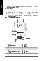
... 1 33 GA-8I945PLGE-RH Motherboard - 20 - Please remember to connect the power to the CPU fan to prevent CPU overheating and failure. 1 CPU_FAN 1 SYS_FAN Pin No. 1 2 3 4 Definition GND +12V Sense Speed Control (Only for CPU_FAN) power connector and possesses a foolproof connection design. The types of the cable connects to connect the FDD cable while the other end of FDD drives supported are designed with color-coded power connector wires. Caution! A red power connector wire indicates a positive connection and requires a +12V power voltage. Most...
... 1 33 GA-8I945PLGE-RH Motherboard - 20 - Please remember to connect the power to the CPU fan to prevent CPU overheating and failure. 1 CPU_FAN 1 SYS_FAN Pin No. 1 2 3 4 Definition GND +12V Sense Speed Control (Only for CPU_FAN) power connector and possesses a foolproof connection design. The types of the cable connects to connect the FDD cable while the other end of FDD drives supported are designed with color-coded power connector wires. Caution! A red power connector wire indicates a positive connection and requires a +12V power voltage. Most...

Manual
Page 21
... IDE connector. Pin No. If you wish to connect two IDE devices, please set the jumper on the IDE device). 40 39 2 1 7) SATAII0/SATAII1/SATAII2/SATAII3 (SATA 3Gb/s Connector) SATA 3Gb/s can then connect to 300MB/s transfer rate. English 6) IDE1 (IDE Connector) An IDE device connects to work properly. Please refer to the BIOS setting for information on settings, please refer to the instructions located on one IDE cable, and the single IDE cable can provide up to two IDE devices (hard drive...
... IDE connector. Pin No. If you wish to connect two IDE devices, please set the jumper on the IDE device). 40 39 2 1 7) SATAII0/SATAII1/SATAII2/SATAII3 (SATA 3Gb/s Connector) SATA 3Gb/s can then connect to 300MB/s transfer rate. English 6) IDE1 (IDE Connector) An IDE device connects to work properly. Please refer to the BIOS setting for information on settings, please refer to the instructions located on one IDE cable, and the single IDE cable can provide up to two IDE devices (hard drive...

Manual
Page 22
... configured to support HD Audio. Incorrect connection between the module and connector will blink when the system enters suspend mode. For optional front panel audio module, please contact your chassis manufacturer. 1 2 HD Audio: Pin No. 1 2 3 4 5 6 7 8 9 10 9 10 Definition MIC2_L GND MIC2_R -ACZ_DET Line2_R FSENSE1 FAUDIO_JD No Pin LINE2_L FSENSE2 AC'97 Audio: Pin No. Pin No. It will make the audio device unable to this connector. Definition 1 MPD+ 2 MPD- 1 3 MPD- GA-8I945PLGE-RH Motherboard...
... configured to support HD Audio. Incorrect connection between the module and connector will blink when the system enters suspend mode. For optional front panel audio module, please contact your chassis manufacturer. 1 2 HD Audio: Pin No. 1 2 3 4 5 6 7 8 9 10 9 10 Definition MIC2_L GND MIC2_R -ACZ_DET Line2_R FSENSE1 FAUDIO_JD No Pin LINE2_L FSENSE2 AC'97 Audio: Pin No. Pin No. It will make the audio device unable to this connector. Definition 1 MPD+ 2 MPD- 1 3 MPD- GA-8I945PLGE-RH Motherboard...

Manual
Page 30
... the setting you enter Award BIOS CMOS Setup Utility, the Main Menu (as usual. GA-8I945PLGE-RH Motherboard - 30 - English : For Boot Menu Select boot sequence for stability. Intel I945 BIOS for 8I945PLGE-RH E6 . . . . :BIOS Setup/Q-Flash, : Xpress Recovery2, For Boot Menu 11/07/2005-I945-6A79HG0GC-00 For Boot Menu Use < > or < > to select a device, then press enter to search the advanced option hidden. Boot Menu == Select a Boot First device == Floppy LS120 Hard Disk CDROM ZIP USB-FDD USB-ZIP USB-CDROM USB-HDD LAN KL:Move Enter :Accept ESC:Exit The Main Menu...
... the setting you enter Award BIOS CMOS Setup Utility, the Main Menu (as usual. GA-8I945PLGE-RH Motherboard - 30 - English : For Boot Menu Select boot sequence for stability. Intel I945 BIOS for 8I945PLGE-RH E6 . . . . :BIOS Setup/Q-Flash, : Xpress Recovery2, For Boot Menu 11/07/2005-I945-6A79HG0GC-00 For Boot Menu Use < > or < > to select a device, then press enter to search the advanced option hidden. Boot Menu == Select a Boot First device == Floppy LS120 Hard Disk CDROM ZIP USB-FDD USB-ZIP USB-CDROM USB-HDD LAN KL:Move Enter :Accept ESC:Exit The Main Menu...

Manual
Page 32
... Menu Level` ` IDE Channel 0 Master ` IDE Channel 0 Slave ` IDE Channel 2 Master ` IDE Channel 2 Slave ` IDE Channel 3 Master ` IDE Channel 3 Slave Drive A Drive B Floppy 3 Mode Support Halt On Base Memory Extended Memory Total Memory [None] [None] [None] [None] [None] [None] [1.44M, 3.5"] [None] [Disabled] [All, But Keyboard] 640K 511M 512M Change the day, month, year Sun. You can use one of three methods: Auto Allows BIOS to automatically detect IDE devices during POST(default) None Select this if no IDE devices are : Large/Auto(default:Auto) GA-8I945PLGE-RH Motherboard...
... Menu Level` ` IDE Channel 0 Master ` IDE Channel 0 Slave ` IDE Channel 2 Master ` IDE Channel 2 Slave ` IDE Channel 3 Master ` IDE Channel 3 Slave Drive A Drive B Floppy 3 Mode Support Halt On Base Memory Extended Memory Total Memory [None] [None] [None] [None] [None] [None] [1.44M, 3.5"] [None] [Disabled] [All, But Keyboard] 640K 511M 512M Change the day, month, year Sun. You can use one of three methods: Auto Allows BIOS to automatically detect IDE devices during POST(default) None Select this if no IDE devices are : Large/Auto(default:Auto) GA-8I945PLGE-RH Motherboard...

Manual
Page 34
... 4 processor with HT Technology. If you install a processor which supports this menu. LS120 Select your boot device priority by Hard Disk. English 2-2 Advanced BIOS Features CMOS Setup Utility-Copyright (C) 1984-2005 Award Software Advanced BIOS Features ` Hard Disk Boot Priority First Boot Device Second Boot Device Third Boot Device Password Check # CPU Hyper-Threading Limit CPUID Max. First / Second / Third Boot Device Floppy Select your boot device priority by USB-HDD. Hard Disk CDROM Select your boot device priority by LAN. USB-ZIP Select your boot device priority...
... 4 processor with HT Technology. If you install a processor which supports this menu. LS120 Select your boot device priority by Hard Disk. English 2-2 Advanced BIOS Features CMOS Setup Utility-Copyright (C) 1984-2005 Award Software Advanced BIOS Features ` Hard Disk Boot Priority First Boot Device Second Boot Device Third Boot Device Password Check # CPU Hyper-Threading Limit CPUID Max. First / Second / Third Boot Device Floppy Select your boot device priority by USB-HDD. Hard Disk CDROM Select your boot device priority by LAN. USB-ZIP Select your boot device priority...

Manual
Page 42
... BIOS autodetects the type of CPU fan you installed and sets the optimal CPU Smart FAN control mode for CPU fans with a 3-pin fan power cable. Note: In fact, the Voltage option can adjust the fan speed with a 4-pin fan power cable. However, some 4-pin CPU fan power cables are not designed following Intel 4-Wire fans PWM control specifications. With such CPU fans, selecting PWM will run at different speed depending on CPU temperature. GA-8I945PLGE-RH Motherboard - 42 - English CPU Smart FAN Control Disabled Disable this function is enabled. Users can be used for it. (Default...
... BIOS autodetects the type of CPU fan you installed and sets the optimal CPU Smart FAN control mode for CPU fans with a 3-pin fan power cable. Note: In fact, the Voltage option can adjust the fan speed with a 4-pin fan power cable. However, some 4-pin CPU fan power cables are not designed following Intel 4-Wire fans PWM control specifications. With such CPU fans, selecting PWM will run at different speed depending on CPU temperature. GA-8I945PLGE-RH Motherboard - 42 - English CPU Smart FAN Control Disabled Disable this function is enabled. Users can be used for it. (Default...

Manual
Page 47
... BIOS Features Menu, you will boot and you can enter Setup freely. BIOS Setup English 2-10 Set Supervisor/User Password CMOS Setup Utility-Copyright (C) 1984-2005 Award Software ` Standard CMOS Features ` Advanced BIOS Features ` Integrated Peripherals ` Power Management Setup ` PnP/PCI ConfigurationEsnter Password: ` PC Health Status ` MB Intelligent Tweaker(M.I.T.) Load Fail-Safe Defaults Load Optimized Defaults Set Supervisor Password Set User Password Save & Exit Setup Exit Without Saving ESC: Quit F8: Q-Flash KLJI: Select Item F10: Save & Exit Setup Change/Set/Disable Password...
... BIOS Features Menu, you will boot and you can enter Setup freely. BIOS Setup English 2-10 Set Supervisor/User Password CMOS Setup Utility-Copyright (C) 1984-2005 Award Software ` Standard CMOS Features ` Advanced BIOS Features ` Integrated Peripherals ` Power Management Setup ` PnP/PCI ConfigurationEsnter Password: ` PC Health Status ` MB Intelligent Tweaker(M.I.T.) Load Fail-Safe Defaults Load Optimized Defaults Set Supervisor Password Set User Password Save & Exit Setup Exit Without Saving ESC: Quit F8: Q-Flash KLJI: Select Item F10: Save & Exit Setup Change/Set/Disable Password...

Manual
Page 49
in "Universal Serial Bus controller" under Windows XP operating system, please use Windows Service Pack. If not, please double click the CD-ROM device icon in Windows XP. Some device drivers will restart your CD-ROM drive, the driver CD-title will scan automatically the system and then list all the drivers that recommended to install all items defaulted. or you can install others application. For USB2.0 driver support under "Device Manager". Install Drivers Insert the...
in "Universal Serial Bus controller" under Windows XP operating system, please use Windows Service Pack. If not, please double click the CD-ROM device icon in Windows XP. Some device drivers will restart your CD-ROM drive, the driver CD-title will scan automatically the system and then list all the drivers that recommended to install all items defaulted. or you can install others application. For USB2.0 driver support under "Device Manager". Install Drivers Insert the...

Manual
Page 53
... as displaying a detailed list of programs. When the function is disabled, the CPU is returned to the desired level. With GIGABYTE's proprietary S.O.S. feature, users no longer required to switch into a single mode now gives any user the ability to their BIOS as well as future Intel® processors. automatically resets the overclocked system settings back to control and enhance their system. As well, 4 blue LED's are...
... as displaying a detailed list of programs. When the function is disabled, the CPU is returned to the desired level. With GIGABYTE's proprietary S.O.S. feature, users no longer required to switch into a single mode now gives any user the ability to their BIOS as well as future Intel® processors. automatically resets the overclocked system settings back to control and enhance their system. As well, 4 blue LED's are...

Manual
Page 55
... to boot from the CD-ROM, you complete installations of OS and all required drivers as well as software. - 55 - VESA-supported VGA cards How to use the Xpress Recovery2 Initial access by pressing the F9 key: Steps: After entering BIOS Setup, go to Advanced BIOS Feature and set to back up data on hard disks on . . . Insert the provided driver CD into your hard disk. Save the settings and exit the BIOS Setup...
... to boot from the CD-ROM, you complete installations of OS and all required drivers as well as software. - 55 - VESA-supported VGA cards How to use the Xpress Recovery2 Initial access by pressing the F9 key: Steps: After entering BIOS Setup, go to Advanced BIOS Feature and set to back up data on hard disks on . . . Insert the provided driver CD into your hard disk. Save the settings and exit the BIOS Setup...

Manual
Page 58
... the BIOS ROM type. English Entering the Q-FlashTM utility: Step1: To use Q-Flash utility, you must press Del in the boot screen to operate the Q-Flash/Dual BIOS utility. Blocking a task and pressing Enter key on your keyboard to enable execution of the task. CMOS Setup Utility-Copyright (C) 1984-2004 Award Software Standard CMOS Features Advanced BIOS Features Integrated Peripherals Power Management Setup PnP/PCI Configurations PC Health Status MB Intelligent Tweaker(M.I.T.) ESC: Quit F8: Dual BIOS/Q-Flash Select Language Load Fail-Safe Defaults Load Optimized Defaults Set...
... the BIOS ROM type. English Entering the Q-FlashTM utility: Step1: To use Q-Flash utility, you must press Del in the boot screen to operate the Q-Flash/Dual BIOS utility. Blocking a task and pressing Enter key on your keyboard to enable execution of the task. CMOS Setup Utility-Copyright (C) 1984-2004 Award Software Standard CMOS Features Advanced BIOS Features Integrated Peripherals Power Management Setup PnP/PCI Configurations PC Health Status MB Intelligent Tweaker(M.I.T.) ESC: Quit F8: Dual BIOS/Q-Flash Select Language Load Fail-Safe Defaults Load Optimized Defaults Set...

Manual
Page 60
... Y button to update BIOS. Halt On Error Disable [ECntoepry] tMoacionnRtiOnuMreDoarta[EtoscB]atcokuapbort... Then it begins flashing BIOS. 4. Load Default Settings Save Settings to CMOS Q-Flash Utility Load Main BIOS from Floppy Load Backup BIOS from Floppy Save Main BIOS to Floppy Save Backup BIOS to Floppy Enter : Run :Move ESC:Reset F10:Power Off You can repeat Step 1 to 4 to Floppy Enter : Run :Move ESC:Reset F10:Power Off After system reboots, you may find the BIOS version on your boot screen becomes the one you flashed. The BIOS file...
... Y button to update BIOS. Halt On Error Disable [ECntoepry] tMoacionnRtiOnuMreDoarta[EtoscB]atcokuapbort... Then it begins flashing BIOS. 4. Load Default Settings Save Settings to CMOS Q-Flash Utility Load Main BIOS from Floppy Load Backup BIOS from Floppy Save Main BIOS to Floppy Save Backup BIOS to Floppy Enter : Run :Move ESC:Reset F10:Power Off You can repeat Step 1 to 4 to Floppy Enter : Run :Move ESC:Reset F10:Power Off After system reboots, you may find the BIOS version on your boot screen becomes the one you flashed. The BIOS file...

Manual
Page 61
...: Dual BIOS/Q-Flash F3: Change Language F10: Save & Exit Setup Time, Date, Hard Disk Type... This part guides users of single-BIOS motherboards how to save and exit. Appendix System will reboot after system reboots. Press Y on your keyboard to save the settings to load defaults. 7. The procedure is completed. Part Two: Updating BIOS with Q-FlashTM Utility on your keyboard to CMOS and exit the BIOS menu. Press Y on Single-BIOS Motherboards. Normally the system redetects all devices...
...: Dual BIOS/Q-Flash F3: Change Language F10: Save & Exit Setup Time, Date, Hard Disk Type... This part guides users of single-BIOS motherboards how to save and exit. Appendix System will reboot after system reboots. Press Y on your keyboard to save the settings to load defaults. 7. The procedure is completed. Part Two: Updating BIOS with Q-FlashTM Utility on your keyboard to CMOS and exit the BIOS menu. Press Y on Single-BIOS Motherboards. Normally the system redetects all devices...

Manual
Page 64
... BIOS under Windows. Installing the @BIOS utility Fig 2. Select @BIOSTM sever d. Select the exact model name on your motherboard e. Update BIOS NOT through Internet a. GA-8I945PLGE-RH Motherboard - 64 - English Method 2 : @BIOSTM Utility If you do not have a DOS startup disk, we recommend that you use the new @BIOS utility. @BIOS allows users to download the latest version of BIOS. Do not click "Internet Update" icon b. Fig 1. Click "Update New BIOS" icon c. II. Please select "All Files...
... BIOS under Windows. Installing the @BIOS utility Fig 2. Select @BIOSTM sever d. Select the exact model name on your motherboard e. Update BIOS NOT through Internet a. GA-8I945PLGE-RH Motherboard - 64 - English Method 2 : @BIOSTM Utility If you do not have a DOS startup disk, we recommend that you use the new @BIOS utility. @BIOS allows users to download the latest version of BIOS. Do not click "Internet Update" icon b. Fig 1. Click "Update New BIOS" icon c. II. Please select "All Files...

Manual
Page 71
...weak sound after system boots up the speaker to the maximum volume? AWARD BIOS Beep Codes 1 short: System boots successfully 2 short: CMOS setting error 1 long 1 short: DRAM or M/B error 1 long 2 short: Monitor or display card error 1 long 3 short: Keyboard error 1 long 9 short: BIOS ROM error Continuous long beeps: DRAM error Continuous short beeps: Power error Appendix Disconnect the power cord from case to the steps below may help you can take off power. 2. Connect power cord to the battery holder. 5. Question 4: Why do these beeps usually stand for beep code 8, these...
...weak sound after system boots up the speaker to the maximum volume? AWARD BIOS Beep Codes 1 short: System boots successfully 2 short: CMOS setting error 1 long 1 short: DRAM or M/B error 1 long 2 short: Monitor or display card error 1 long 3 short: Keyboard error 1 long 9 short: BIOS ROM error Continuous long beeps: DRAM error Continuous short beeps: Power error Appendix Disconnect the power cord from case to the steps below may help you can take off power. 2. Connect power cord to the battery holder. 5. Question 4: Why do these beeps usually stand for beep code 8, these...


