Manual
Page 1
GA-8I945GMF Intel® Pentium® D / Pentium® 4 LGA775 Processor Motherboard User's Manual Rev. 1005 12ME-8I945GMF-1005R * The WEEE marking on the product indicates this product must not be disposed of with user's other household waste and must be handed over to a designated collection point for the recycling of waste electrical and electronic equipment!! * The WEEE marking applies only in European Union's member states.
GA-8I945GMF Intel® Pentium® D / Pentium® 4 LGA775 Processor Motherboard User's Manual Rev. 1005 12ME-8I945GMF-1005R * The WEEE marking on the product indicates this product must not be disposed of with user's other household waste and must be handed over to a designated collection point for the recycling of waste electrical and electronic equipment!! * The WEEE marking applies only in European Union's member states.

Manual
Page 2
Motherboard GA-8I945GMF Apr. 26, 2005 Motherboard GA-8I945GMF Apr. 26, 2005
Motherboard GA-8I945GMF Apr. 26, 2005 Motherboard GA-8I945GMF Apr. 26, 2005
Manual
Page 4
Table of Content GA-8I945GMF Motherboard Layout 6 Block Diagram ...7 Chapter 1 Hardware Installation 9 1-1 Considerations Prior to Installation 9 1-2 Feature Summary 10 1-3 Installation of the CPU and Heatsink 12 1-3-1 Installation of the CPU 12 1-3-2 ...
Table of Content GA-8I945GMF Motherboard Layout 6 Block Diagram ...7 Chapter 1 Hardware Installation 9 1-1 Considerations Prior to Installation 9 1-2 Feature Summary 10 1-3 Installation of the CPU and Heatsink 12 1-3-1 Installation of the CPU 12 1-3-2 ...
Manual
Page 6
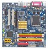
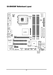
GA-8I945GMF Motherboard Layout COMA LPT KB_MS ATX_12V LGA775 CPU_FAN IT8712F RF_ID ATX VGA GA-8I945GMF USB USB 1394 LAN Intel 945G F_AUDIO AUDIO1 AUDIO2 PCIE_16 PCI1 Marvell 8053 PCI2 CD_IN PCIE_1 CODEC SPDIF_IO COMB DDRII1 DDRII2 DDRII3 DDRII4 IDE FDD BIOS SATAII2_3 ICH7 BATTERY TSB43AB23 SATAII0_1 CI SYS_FAN F1_1394 F2_1394 GREEN_USB F_USB CLR_CMOS F_PANEL PWR_LED (Optional) - 6 -
GA-8I945GMF Motherboard Layout COMA LPT KB_MS ATX_12V LGA775 CPU_FAN IT8712F RF_ID ATX VGA GA-8I945GMF USB USB 1394 LAN Intel 945G F_AUDIO AUDIO1 AUDIO2 PCIE_16 PCI1 Marvell 8053 PCI2 CD_IN PCIE_1 CODEC SPDIF_IO COMB DDRII1 DDRII2 DDRII3 DDRII4 IDE FDD BIOS SATAII2_3 ICH7 BATTERY TSB43AB23 SATAII0_1 CI SYS_FAN F1_1394 F2_1394 GREEN_USB F_USB CLR_CMOS F_PANEL PWR_LED (Optional) - 6 -
Manual
Page 7
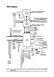
... Speaker Out Side Speaker Out MIC Line-Out Line-In SPDIF In SPDIF Out PCICLK (33MHz) (Note) To use a DDRII 667 memory module on the motherboard, you must install an 800/1066MHz FSB processor . - 7 -
... Speaker Out Side Speaker Out MIC Line-Out Line-In SPDIF In SPDIF Out PCICLK (33MHz) (Note) To use a DDRII 667 memory module on the motherboard, you must install an 800/1066MHz FSB processor . - 7 -

Manual
Page 9
... the user manual. 3. Damage due to installing the electronic components, please have a problem related to be an unofficial Gigabyte product. - 9 - When handling the motherboard, avoid touching any installation steps or have these items on the motherboard or within a electrostatic shielding container. 5. Prior to come in the provided manual. 3. Before using the product, please...
... the user manual. 3. Damage due to installing the electronic components, please have a problem related to be an unofficial Gigabyte product. - 9 - When handling the motherboard, avoid touching any installation steps or have these items on the motherboard or within a electrostatic shielding container. 5. Prior to come in the provided manual. 3. Before using the product, please...
Manual
Page 10
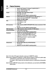
GA-8I945GMF Motherboard - 10 - For example, 4 GB of memory is reserved for system usage and therefore the actual memory size is less than the stated amount. English 1-2 Feature ... chip (10/100/1000 Mbit) 1 RJ 45 port Supported on the Win 2000/XP operating systems (Note 1) For further CPU support information, please go to GIGABYTE's website. (Note 2) Due to standard PC architecture, a certain amount of memory size will instead be shown as 3.xxGB memory during system startup. (Note 3) To use...
GA-8I945GMF Motherboard - 10 - For example, 4 GB of memory is reserved for system usage and therefore the actual memory size is less than the stated amount. English 1-2 Feature ... chip (10/100/1000 Mbit) 1 RJ 45 port Supported on the Win 2000/XP operating systems (Note 1) For further CPU support information, please go to GIGABYTE's website. (Note 2) Due to standard PC architecture, a certain amount of memory size will instead be shown as 3.xxGB memory during system startup. (Note 3) To use...
Manual
Page 12
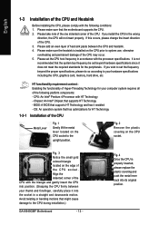
..., memory, hard drive, etc. Please make sure that might cause damage to the upright position. Avoid twisting or bending motions that the motherboard supports the CPU. 2. If this occurs, please change the insert direction of the CPU. Please take note of the one indented corner ... HT Technology and has it into its original position. Fig. 2 Remove the plastic covering on the CPU socket to the CPU during installation.) GA-8I945GMF Motherboard - 12 - Please add an even layer of heat sink paste between your thumb and forefinger, carefully place it enabled - BIOS: A BIOS...
..., memory, hard drive, etc. Please make sure that might cause damage to the upright position. Avoid twisting or bending motions that the motherboard supports the CPU. 2. If this occurs, please change the insert direction of the CPU. Please take note of the one indented corner ... HT Technology and has it into its original position. Fig. 2 Remove the plastic covering on the CPU socket to the CPU during installation.) GA-8I945GMF Motherboard - 12 - Please add an even layer of heat sink paste between your thumb and forefinger, carefully place it enabled - BIOS: A BIOS...

Manual
Page 13
...Male Push Pin The top of Female Push Pin Female Push Pin Fig.1 Please apply an even layer of heatsink paste on the surface of motherboard after installing. If the push pin is inserted as a result of hardening of the heatsink to the heatsink installation section of the user manual...make sure the Male and Female push pin are joined closely. (for detailed installation instructions, please refer to the CPU fan header located on the motherboard. Fig. 6 Finally, please attach the power connector of the heatsink paste.To prevent such an occurrence, it is only for heat dissipation or ...
...Male Push Pin The top of Female Push Pin Female Push Pin Fig.1 Please apply an even layer of heatsink paste on the surface of motherboard after installing. If the push pin is inserted as a result of hardening of the heatsink to the heatsink installation section of the user manual...make sure the Male and Female push pin are joined closely. (for detailed installation instructions, please refer to the CPU fan header located on the motherboard. Fig. 6 Finally, please attach the power connector of the heatsink paste.To prevent such an occurrence, it is only for heat dissipation or ...
Manual
Page 14
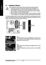
The motherboard supports DDR II memory modules, whereby BIOS will automatically detect memory capacity and specifications. Then push it down....of Memory Before installing the memory modules, please comply with each slot. It is recommended that the computer power is supported by the motherboard. Before installing or removing memory modules, please make sure that they can differ with the following conditions: 1. A memory module can only... to insert the module, please switch the direction. Memory modules are unable to lock the DIMM module. GA-8I945GMF Motherboard - 14 -
The motherboard supports DDR II memory modules, whereby BIOS will automatically detect memory capacity and specifications. Then push it down....of Memory Before installing the memory modules, please comply with each slot. It is recommended that the computer power is supported by the motherboard. Before installing or removing memory modules, please make sure that they can differ with the following conditions: 1. A memory module can only... to insert the module, please switch the direction. Memory modules are unable to lock the DIMM module. GA-8I945GMF Motherboard - 14 -
Manual
Page 16
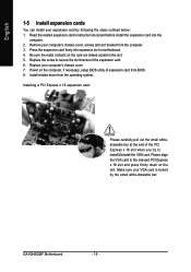
...Please align the VGA card to the onboard PCI Express x 16 slot and press firmly down on the card are indeed seated in motherboard. 4. Be sure the metal contacts on the slot .Make sure your VGA card is locked by following the steps outlined below: ...the related expansion card's instruction document before install the expansion card into expansion slot in the slot. 5. Remove your computer's chassis cover. 7. GA-8I945GMF Motherboard - 16 - Press the expansion card firmly into the computer. 2. English 1-5 Install expansion cards You can install your expansion card by the small...
...Please align the VGA card to the onboard PCI Express x 16 slot and press firmly down on the card are indeed seated in motherboard. 4. Be sure the metal contacts on the slot .Make sure your VGA card is locked by following the steps outlined below: ...the related expansion card's instruction document before install the expansion card into expansion slot in the slot. 5. Remove your computer's chassis cover. 7. GA-8I945GMF Motherboard - 16 - Press the expansion card firmly into the computer. 2. English 1-5 Install expansion cards You can install your expansion card by the small...
Manual
Page 18
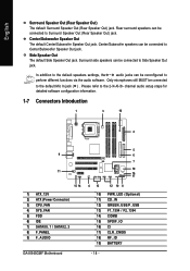
... setup steps for detailed software configuration information. 1-7 Connectors Introduction 1 3 18 2 9 11 15 14 1) ATX_12V 2) ATX (Power Connector) 3) CPU_FAN 4) SYS_FAN 5) FDD 6) IDE 7) SATAII0_1 / SATAII2_3 8) F_PANEL 9) F_AUDIO GA-8I945GMF Motherboard 5 6 7 19 16 17 4 13 12 10 8 10) PWR_LED (Optional) 11) CD_IN 12) GREEN_USB/F_USB 13) F1_1394 / F2_1394 14) COMB 15) SPDIF_IO 16) CI 17) CLR_CMOS...
... setup steps for detailed software configuration information. 1-7 Connectors Introduction 1 3 18 2 9 11 15 14 1) ATX_12V 2) ATX (Power Connector) 3) CPU_FAN 4) SYS_FAN 5) FDD 6) IDE 7) SATAII0_1 / SATAII2_3 8) F_PANEL 9) F_AUDIO GA-8I945GMF Motherboard 5 6 7 19 16 17 4 13 12 10 8 10) PWR_LED (Optional) 11) CD_IN 12) GREEN_USB/F_USB 13) F1_1394 / F2_1394 14) COMB 15) SPDIF_IO 16) CI 17) CLR_CMOS...
Manual
Page 19
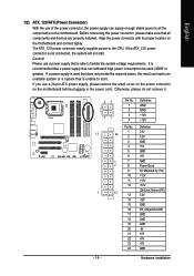
...are properly installed. Please use a power supply that is unable to start . Hardware Installation Align the power connector with its proper location on the motherboard and connect tightly. If a power supply is able to an unstable system or a system that is used (300W or greater). If you use... 1/2) ATX_12V/ATX (Power Connector) With the use a 24-pin ATX power supply, please remove the small cover on the power connector on the motherboard before plugging in the power cord ; If the ATX_12V power connector is recommended that a power supply that all the components on the...
...are properly installed. Please use a power supply that is unable to start . Hardware Installation Align the power connector with its proper location on the motherboard and connect tightly. If a power supply is able to an unstable system or a system that is used (300W or greater). If you use... 1/2) ATX_12V/ATX (Power Connector) With the use a 24-pin ATX power supply, please remove the small cover on the power connector on the motherboard before plugging in the power cord ; If the ATX_12V power connector is recommended that a power supply that all the components on the...
Manual
Page 20
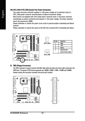
Most coolers are : 360KB, 720KB, 1.2MB, 1.44MB and 2.88MB. Please remember to connect the power to the cooler to the pin1 position. 34 33 GA-8I945GMF Motherboard 2 1 - 20 - The types of the cable connects to the FDD drive. Please connect the red power connector wire to prevent system overheating and failure. Caution! A ...
Most coolers are : 360KB, 720KB, 1.2MB, 1.44MB and 2.88MB. Please remember to connect the power to the cooler to the pin1 position. 34 33 GA-8I945GMF Motherboard 2 1 - 20 - The types of the cable connects to the FDD drive. Please connect the red power connector wire to prevent system overheating and failure. Caution! A ...
Manual
Page 22
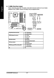
... assignment below. Pin 3: NC Pin 4: Data(-) Open: Normal Close: Reset Hardware System Open: Normal Close: Power On/Off Pin 1: LED anode(+) Pin 2: LED cathode(-) NC GA-8I945GMF Motherboard - 22 -
... assignment below. Pin 3: NC Pin 4: Data(-) Open: Normal Close: Reset Hardware System Open: Normal Close: Power On/Off Pin 1: LED anode(+) Pin 2: LED cathode(-) NC GA-8I945GMF Motherboard - 22 -
Manual
Page 24
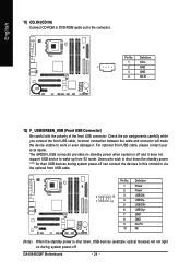
... it . The GREEN_USB connector provides no standby power when system is shut down the standby power (note) for their USB devices during system power-off. GA-8I945GMF Motherboard - 24 - Pin No. English 11) CD_IN (CD IN) Connect CD-ROM or DVD-ROM audio out to wake up from S3 mode. Definition 1 Power 2 Power...
... it . The GREEN_USB connector provides no standby power when system is shut down the standby power (note) for their USB devices during system power-off. GA-8I945GMF Motherboard - 24 - Pin No. English 11) CD_IN (CD IN) Connect CD-ROM or DVD-ROM audio out to wake up from S3 mode. Definition 1 Power 2 Power...
Manual
Page 26
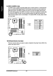
... SPDIF SPDIFI GND GND 16) CI (Chassis Intrusion, Case Open) This 2-pin connector allows your system to work or even damage it. Definition 1 1 Signal 2 GND GA-8I945GMF Motherboard - 26 - Incorrect connection between the cable and connector will make the device unable to enable or disable the "Case Open" item in BIOS, if the...
... SPDIF SPDIFI GND GND 16) CI (Chassis Intrusion, Case Open) This 2-pin connector allows your system to work or even damage it. Definition 1 1 Signal 2 GND GA-8I945GMF Motherboard - 26 - Incorrect connection between the cable and connector will make the device unable to enable or disable the "Case Open" item in BIOS, if the...
Manual
Page 28
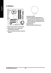
.... Take out the battery gently and put it aside for one minute). 3.Re-install the battery. 4.Plug the power cord and turn ON the computer. GA-8I945GMF Motherboard - 28 - If you can use a metal object to connect the positive and negative pins in the battery holder to the manufacturer's instructions. English 19) BAT...
.... Take out the battery gently and put it aside for one minute). 3.Re-install the battery. 4.Plug the power cord and turn ON the computer. GA-8I945GMF Motherboard - 28 - If you can use a metal object to connect the positive and negative pins in the battery holder to the manufacturer's instructions. English 19) BAT...
Manual
Page 29
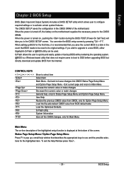
...the first time, it is turned on, pushing the button during the BIOS POST (Power-On Self Test) will take you to a new BIOS, either Gigabyte's Q-Flash or @BIOS utility can enter the BIOS setup screen by pressing "Ctrl + F1". You can be reset to DOS before upgrading BIOS but directly...- Q-Flash allows the user to quickly and easily update or backup BIOS without entering the operating system. @BIOS is displayed at the bottom of the motherboard. Exit current page and return to Main Menu Increase the numeric value or make changes Decrease the numeric value or make changes General help window...
...the first time, it is turned on, pushing the button during the BIOS POST (Power-On Self Test) will take you to a new BIOS, either Gigabyte's Q-Flash or @BIOS utility can enter the BIOS setup screen by pressing "Ctrl + F1". You can be reset to DOS before upgrading BIOS but directly...- Q-Flash allows the user to quickly and easily update or backup BIOS without entering the operating system. @BIOS is displayed at the bottom of the motherboard. Exit current page and return to Main Menu Increase the numeric value or make changes Decrease the numeric value or make changes General help window...
Manual
Page 30
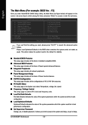
... & Exit Setup Time, Date, Hard Disk Type... If you can't find the setting you enter Award BIOS CMOS Setup Utility, the Main Menu (as usual. GA-8I945GMF Motherboard - 30 - English The Main Menu (For example: BIOS Ver. : F2) Once you want, please press "Ctrl+F1" to search the advanced option hidden. This action...
... & Exit Setup Time, Date, Hard Disk Type... If you can't find the setting you enter Award BIOS CMOS Setup Utility, the Main Menu (as usual. GA-8I945GMF Motherboard - 30 - English The Main Menu (For example: BIOS Ver. : F2) Once you want, please press "Ctrl+F1" to search the advanced option hidden. This action...


