
Manual
Page 5
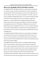
... improve the system's ability. Supports the drivers for the DMA/UDMA function Includes one embedded CPU and firmware on a local processor architecture Compatible with PCI Local bus specification v2.2. Supports ANSI ATA proposal PIO modes 0,1,2,3,4 with 4 drives. Supports PCI power ...the RAID 0/1/0+1 function Supports the JBOD function Supports the Scatter/Gather function for windows 98SE/Me/XP, Windows NT 4.0, Windows 2000 and Linux v2,4,1,0 5 Low CPU utilization based on system to handle the RAID function. It can easily install our systems to reduce power consumption.
... improve the system's ability. Supports the drivers for the DMA/UDMA function Includes one embedded CPU and firmware on a local processor architecture Compatible with PCI Local bus specification v2.2. Supports ANSI ATA proposal PIO modes 0,1,2,3,4 with 4 drives. Supports PCI power ...the RAID 0/1/0+1 function Supports the JBOD function Supports the Scatter/Gather function for windows 98SE/Me/XP, Windows NT 4.0, Windows 2000 and Linux v2,4,1,0 5 Low CPU utilization based on system to handle the RAID function. It can easily install our systems to reduce power consumption.
Manual
Page 6
..., we provide each OS a corresponding driver so that your systems and the IDE RAID system have to enhance the performance. When a system is in high CPU operation or PCI traffic, users won't have the same data and it will start the rebuild function automatically and save data back to combine RAID... the lowest speed of PIO mode drive to achieve the best performance and get the merit of ATA/133 drive. Similarly, this system embeds a local CPU to deal with the RAID function and it can provide users a RAID system with PCI spec. Similarly, it also provides PCI 33MHz interface and is...
..., we provide each OS a corresponding driver so that your systems and the IDE RAID system have to enhance the performance. When a system is in high CPU operation or PCI traffic, users won't have the same data and it will start the rebuild function automatically and save data back to combine RAID... the lowest speed of PIO mode drive to achieve the best performance and get the merit of ATA/133 drive. Similarly, this system embeds a local CPU to deal with the RAID function and it can provide users a RAID system with PCI spec. Similarly, it also provides PCI 33MHz interface and is...
Manual
Page 4
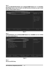
...ESC: Exit F1: General Help F7: Optimized Defaults SATA Hard Drives Configurations (Intel ICH7R) - 4 - Press to 3 No-Execute Memory Protect CPU Enhanced Halt (C1E) CPU Thermal Monitor 2(TM2) CPU EIST Function (µù) [Press Enter] [CDROM] [Hard Disk] [CDROM] [Setup] [Enabled] [Disabled] [Enabled] [Enabled] [Enabled]...-2005 Award Software Advanced BIOS Features ` Hard Disk Boot Priority First Boot Device Second Boot Device Third Boot Device Password Check # CPU Hyper-Threading Limit CPUID Max. KL: Move PU/PD/+/-: Change Priority F10: Save ESC: Exit Figure 2 Step 3: Set First...
...ESC: Exit F1: General Help F7: Optimized Defaults SATA Hard Drives Configurations (Intel ICH7R) - 4 - Press to 3 No-Execute Memory Protect CPU Enhanced Halt (C1E) CPU Thermal Monitor 2(TM2) CPU EIST Function (µù) [Press Enter] [CDROM] [Hard Disk] [CDROM] [Setup] [Enabled] [Disabled] [Enabled] [Enabled] [Enabled]...-2005 Award Software Advanced BIOS Features ` Hard Disk Boot Priority First Boot Device Second Boot Device Third Boot Device Password Check # CPU Hyper-Threading Limit CPUID Max. KL: Move PU/PD/+/-: Change Priority F10: Save ESC: Exit Figure 2 Step 3: Set First...

Manual
Page 4
Table of Contents GA-8I945G Pro Motherboard Layout 6 GA-8I945G Motherboard Layout 7 Block Diagram ...8 Chapter 1 Hardware Installation 9 1-1 Considerations Prior to Installation 9 1-2 Feature Summary 10 1-3 Installation of the CPU and Heatsink 12 1-3-1 Installation of the CPU 12 1-3-2 Installation of the Heatsink 13 1-4 Installing/Removing Cool-Plus (Northbridge Cooling Fan 14 1-5 Installation of Memory 14 1-6 Installation of Expansion Cards 16...
Table of Contents GA-8I945G Pro Motherboard Layout 6 GA-8I945G Motherboard Layout 7 Block Diagram ...8 Chapter 1 Hardware Installation 9 1-1 Considerations Prior to Installation 9 1-2 Feature Summary 10 1-3 Installation of the CPU and Heatsink 12 1-3-1 Installation of the CPU 12 1-3-2 Installation of the Heatsink 13 1-4 Installing/Removing Cool-Plus (Northbridge Cooling Fan 14 1-5 Installation of Memory 14 1-6 Installation of Expansion Cards 16...
Manual
Page 9
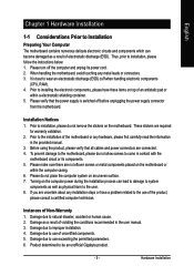
... the computer casing. 6. To prevent damage to the motherboard, please do not allow screws to wear an electrostatic discharge (ESD) cuff when handling electronic components (CPU, RAM). 4. If you are connected. 4. Damage as a result of violating the conditions recommended in the provided manual. 3. Hardware Installation Damage due to the ...that the power supply is best to come in contact with the motherboard circuit or its power cord. 2. Damage due to be an unofficial Gigabyte product. - 9 - Prior to the user. 8. Installation Notices 1. Turning on an uneven surface. 7.
... the computer casing. 6. To prevent damage to the motherboard, please do not allow screws to wear an electrostatic discharge (ESD) cuff when handling electronic components (CPU, RAM). 4. If you are connected. 4. Damage as a result of violating the conditions recommended in the provided manual. 3. Hardware Installation Damage due to the ...that the power supply is best to come in contact with the motherboard circuit or its power cord. 2. Damage due to be an unofficial Gigabyte product. - 9 - Prior to the user. 8. Installation Notices 1. Turning on an uneven surface. 7.

Manual
Page 10
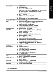
Only for GA-8I945G. Only for GA-8I945G Pro. GA-8I945G Pro/GA-8I945G Motherboard - 10 - English 1-2 Feature Summary CPU Š Š Š Chipset Š Š Š Memory Š Š Š Slots Š Š Š IDE Connections Š Š FDD Connections Š ...Onboard Broadcom 5789 chip (10/100/1000 Mbit) 1 RJ 45 port Supported on the Win 2000/XP operating systems (Note 1) For further CPU support information, please go to GIGABYTE's website. (Note 2) Due to 4GB memory) (Note 2) Supports 1.8V DDR II DIMM Supports dual channel DDR II 667(Note 3)/...
Only for GA-8I945G. Only for GA-8I945G Pro. GA-8I945G Pro/GA-8I945G Motherboard - 10 - English 1-2 Feature Summary CPU Š Š Š Chipset Š Š Š Memory Š Š Š Slots Š Š Š IDE Connections Š Š FDD Connections Š ...Onboard Broadcom 5789 chip (10/100/1000 Mbit) 1 RJ 45 port Supported on the Win 2000/XP operating systems (Note 1) For further CPU support information, please go to GIGABYTE's website. (Note 2) Due to 4GB memory) (Note 2) Supports 1.8V DDR II DIMM Supports dual channel DDR II 667(Note 3)/...
Manual
Page 11
... onboard BIOS Š IT8712 Š System voltage detection Š CPU temperature detection Š CPU / System / Power fan speed detection Š CPU warning temperature Š CPU / System / Power fan failure warning Š CPU smart fan control Š Use of licensed AWARD BIOS Š Supports... Q-Flash/Dual BIOS /Multilanguage Š Supports @BIOS Š Supports EasyTune 5 Š Over Voltage via BIOS (CPU/DDR/PCIE/FSB) Š Over Clock via BIOS (CPU/DDR) Š ATX form factor; 30.5cm x 22.0cm Only for GA-8I945G Pro...
... onboard BIOS Š IT8712 Š System voltage detection Š CPU temperature detection Š CPU / System / Power fan speed detection Š CPU warning temperature Š CPU / System / Power fan failure warning Š CPU smart fan control Š Use of licensed AWARD BIOS Š Supports... Q-Flash/Dual BIOS /Multilanguage Š Supports @BIOS Š Supports EasyTune 5 Š Over Voltage via BIOS (CPU/DDR/PCIE/FSB) Š Over Clock via BIOS (CPU/DDR) Š ATX form factor; 30.5cm x 22.0cm Only for GA-8I945G Pro...

Manual
Page 12
... forefinger, carefully place it enabled - Please make sure the heatsink is installed on the CPU socket to the CPU during installation.) GA-8I945G Pro/GA-8I945G Motherboard - 12 - Please add an even layer of heat sink paste between your hardware specifications including the CPU, graphics card, memory, hard drive, etc. OS: An operation system that might cause damage...
... forefinger, carefully place it enabled - Please make sure the heatsink is installed on the CPU socket to the CPU during installation.) GA-8I945G Pro/GA-8I945G Motherboard - 12 - Please add an even layer of heat sink paste between your hardware specifications including the CPU, graphics card, memory, hard drive, etc. OS: An operation system that might cause damage...
Manual
Page 13
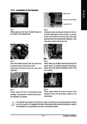
...the motherboard. Fig. 2 (Turning the push pin along the direction of arrow is to remove the heatsink, on the contrary, is to the CPU fan header located on the motherboard.Pressing down the push pins diagonally. Fig. 6 Finally, please attach the power connector of the heatsink to install.)... Please note the direction of arrow sign on the surface of the installed CPU. English 1-3-2 Installation of the Heatsink Male Push Pin The top of Female Push Pin Female Push Pin Fig.1 Please apply an even layer of...
...the motherboard. Fig. 2 (Turning the push pin along the direction of arrow is to remove the heatsink, on the contrary, is to the CPU fan header located on the motherboard.Pressing down the push pins diagonally. Fig. 6 Finally, please attach the power connector of the heatsink to install.)... Please note the direction of arrow sign on the surface of the installed CPU. English 1-3-2 Installation of the Heatsink Male Push Pin The top of Female Push Pin Female Push Pin Fig.1 Please apply an even layer of...

Manual
Page 19
... does not provide the required power, the result can withstand high power consumption be used (300W or greater). If a power supply is unable to the CPU. If you use a power supply that can lead to handle the system voltage requirements. Hardware Installation The ATX_12V power connector mainly supplies power to start...
... does not provide the required power, the result can withstand high power consumption be used (300W or greater). If a power supply is unable to the CPU. If you use a power supply that can lead to handle the system voltage requirements. Hardware Installation The ATX_12V power connector mainly supplies power to start...

Manual
Page 20
... wire (GND). Please remember to connect the power to the CPU fan to prevent system overheating and failure. Definition 1 +12V 2 GND 1 Only for CPU_FAN) power connector and possesses a foolproof connection design. Most coolers are designed with color-coded power connector wires. GA-8I945G Pro/GA-8I945G Motherboard - 20 - The black connector wire is GND) Pin No...
... wire (GND). Please remember to connect the power to the CPU fan to prevent system overheating and failure. Definition 1 +12V 2 GND 1 Only for CPU_FAN) power connector and possesses a foolproof connection design. Most coolers are designed with color-coded power connector wires. GA-8I945G Pro/GA-8I945G Motherboard - 20 - The black connector wire is GND) Pin No...
Manual
Page 30
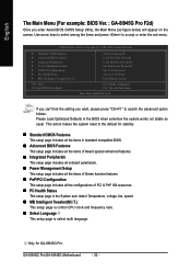
... select among the items and press to search the advanced option hidden. This action makes the system reset to the default for GA-8I945G Pro. GA-8I945G Pro/GA-8I945G Motherboard - 30 - Only for stability. „ Standard CMOS Features This setup page includes all the items in the BIOS when...PC Health Status ` MB Intelligent Tweaker(M.I .T.) This setup page is control CPU clock and frequency ratio. „ Select Language This setup page is select multi language. English The Main Menu (For example: BIOS Ver. : GA-8I945G Pro F2d) Once you want, please press "Ctrl+F1" to accept or ...
... select among the items and press to search the advanced option hidden. This action makes the system reset to the default for GA-8I945G Pro. GA-8I945G Pro/GA-8I945G Motherboard - 30 - Only for stability. „ Standard CMOS Features This setup page includes all the items in the BIOS when...PC Health Status ` MB Intelligent Tweaker(M.I .T.) This setup page is control CPU clock and frequency ratio. „ Select Language This setup page is select multi language. English The Main Menu (For example: BIOS Ver. : GA-8I945G Pro F2d) Once you want, please press "Ctrl+F1" to accept or ...
Manual
Page 33
... errors. (Default value) All, But Diskette The system boot will determine the amount of floppy disk drive A or drive B that has been installed in the CPU's memory address map. Base Memory The POST of the BIOS will not stop for a disk error; BIOS Setup No Errors The system boot will stop...
... errors. (Default value) All, But Diskette The system boot will determine the amount of floppy disk drive A or drive B that has been installed in the CPU's memory address map. Base Memory The POST of the BIOS will not stop for a disk error; BIOS Setup No Errors The system boot will stop...

Manual
Page 34
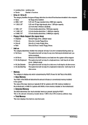
... (Default value) System The system will not boot and will detect automatically and show up , or to exit this function. GA-8I945G Pro/GA-8I945G Motherboard - 34 - First / Second / Third Boot Device Floppy Select your boot device priority by USB-CDROM. Hard Disk Select... Priority First Boot Device Second Boot Device Third Boot Device Password Check # CPU Hyper-Threading Limit CPUID Max. to 3 No-Execute Memory Protect (Note) CPU Enhanced Halt (C1E) (Note) CPU Thermal Monitor 2(TM2) (Note) CPU EIST Function (Note) On-Chip Frame Buffer Size [Press Enter] [Floppy...
... (Default value) System The system will not boot and will detect automatically and show up , or to exit this function. GA-8I945G Pro/GA-8I945G Motherboard - 34 - First / Second / Third Boot Device Floppy Select your boot device priority by USB-CDROM. Hard Disk Select... Priority First Boot Device Second Boot Device Third Boot Device Password Check # CPU Hyper-Threading Limit CPUID Max. to 3 No-Execute Memory Protect (Note) CPU Enhanced Halt (C1E) (Note) CPU Thermal Monitor 2(TM2) (Note) CPU EIST Function (Note) On-Chip Frame Buffer Size [Press Enter] [Floppy...

Manual
Page 35
... frame buffer size to 3 when use older OS like NT4. English CPU Hyper-Threading Enabled Disabled Enables CPU Hyper Threading Feature. CPU Thermal Monitor 2 (TM2) (Note) Enabled Disabled Enable CPU Thermal Monitor 2 (TM2) function. (Default value) Disable CPU Thermal Monitor 2 (TM2) function. CPU EIST Function (Note) Enabled Enable CPU EIST function. (Default value) Disabled Disable EIST function...
... frame buffer size to 3 when use older OS like NT4. English CPU Hyper-Threading Enabled Disabled Enables CPU Hyper Threading Feature. CPU Thermal Monitor 2 (TM2) (Note) Enabled Disabled Enable CPU Thermal Monitor 2 (TM2) function. (Default value) Disable CPU Thermal Monitor 2 (TM2) function. CPU EIST Function (Note) Enabled Enable CPU EIST function. (Default value) Disabled Disable EIST function...

Manual
Page 42
... 80oC / 176oF. Case Opened If the case is closed, "Case Opened" will show "Yes". Monitor CPU temperature at 90oC / 194oF. Only for GA-8I945G Pro. Current CPU/POWER /SYSTEM FAN Speed (RPM) Detect CPU/POWER /SYSTEM Fan speed status automatically. Monitor CPU temperature at 70oC / 158oF. English 2-6 PC Health Status CMOS Setup Utility-Copyright (C) 1984-2005 Award...
... 80oC / 176oF. Case Opened If the case is closed, "Case Opened" will show "Yes". Monitor CPU temperature at 90oC / 194oF. Only for GA-8I945G Pro. Current CPU/POWER /SYSTEM FAN Speed (RPM) Detect CPU/POWER /SYSTEM Fan speed status automatically. Monitor CPU temperature at 70oC / 158oF. English 2-6 PC Health Status CMOS Setup Utility-Copyright (C) 1984-2005 Award...
Manual
Page 43
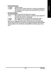
... when you installed and sets the optimal CPU Smart FAN control mode for CPU fans with a 3-pin fan power cable. BIOS Setup Auto BIOS autodetects the type of CPU fan you use a CPU fan with Easy Tune based on CPU temperature. With such CPU fans, selecting PWM will run at different... speed depending on their requirements. CPU Smart FAN Mode This option is available only when CPU Smart FAN Control is enabled, CPU fan will not ...
... when you installed and sets the optimal CPU Smart FAN control mode for CPU fans with a 3-pin fan power cable. BIOS Setup Auto BIOS autodetects the type of CPU fan you use a CPU fan with Easy Tune based on CPU temperature. With such CPU fans, selecting PWM will run at different... speed depending on their requirements. CPU Smart FAN Mode This option is available only when CPU Smart FAN Control is enabled, CPU fan will not ...
Manual
Page 44
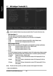
... (Note) High Set clock ratio for frequency-locked CPU to High. (Default value) Low Set clock ratio for GA-8I945G Pro. Turbo Set Robust Graphics Booster to maximize system performance. C.I.A.2 C.I.A.2 (CPU Intelligent Acelerator 2) is not changeable. Sports Set C.I .A.2 to Sports. (Automatically increase CPU frequency(7%,9%) by CPU detection. Auto Set Robust Graphics Booster to Auto. ... F6: Fail-Safe Defaults ESC: Exit F1: General Help F7: Optimized Defaults Incorrect using these features may cause your system broken. GA-8I945G Pro/GA-8I945G Motherboard - 44 -
... (Note) High Set clock ratio for frequency-locked CPU to High. (Default value) Low Set clock ratio for GA-8I945G Pro. Turbo Set Robust Graphics Booster to maximize system performance. C.I.A.2 C.I.A.2 (CPU Intelligent Acelerator 2) is not changeable. Sports Set C.I .A.2 to Sports. (Automatically increase CPU frequency(7%,9%) by CPU detection. Auto Set Robust Graphics Booster to Auto. ... F6: Fail-Safe Defaults ESC: Exit F1: General Help F7: Optimized Defaults Incorrect using these features may cause your system broken. GA-8I945G Pro/GA-8I945G Motherboard - 44 -
Manual
Page 45
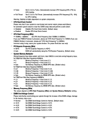
...the increase of the DIMM voltage, damage to the memory may make system can't boot, clear CMOS to Full Thrust. (Automatically increase CPU frequency(17%, 19%) by overclocking your system broken. Auto BIOS will automatically setup the PCI Express Frequency. (Default value) System Memory ...DIMM OverVoltage Control to +0.1V. +0.2V Set DIMM OverVoltage Control to +0.2V. +0.3V +0.4V Set DIMM OverVoltage Control to Turbo. (Automatically increase CPU frequency(15%,17%) by DRAM SPD data. (Default value) for automatic system restart or clear the CMOS setup data and perform a safe restart...
...the increase of the DIMM voltage, damage to the memory may make system can't boot, clear CMOS to Full Thrust. (Automatically increase CPU frequency(17%, 19%) by overclocking your system broken. Auto BIOS will automatically setup the PCI Express Frequency. (Default value) System Memory ...DIMM OverVoltage Control to +0.1V. +0.2V Set DIMM OverVoltage Control to +0.2V. +0.3V +0.4V Set DIMM OverVoltage Control to Turbo. (Automatically increase CPU frequency(15%,17%) by DRAM SPD data. (Default value) for automatic system restart or clear the CMOS setup data and perform a safe restart...
Manual
Page 46
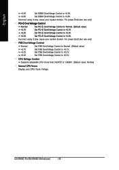
... Control to Normal. (Default value) +0.1V +0.2V +0.3V Set FSB OverVoltage Control to +0.2V. Set FSB OverVoltage Control to +0.2V. GA-8I945G Pro/GA-8I945G Motherboard - 46 - Set FSB OverVoltage Control to +0.3V. English +0.5V Set DIMM OverVoltage Control to +0.5V. +0.6V Set DIMM OverVoltage ...Control to 1.6000V. (Default value: Normal) Normal CPU Vcore Display your CPU Vcore Voltage. For power End-User use only! CPU Voltage Control Supports adjustable CPU Vcore from 0.8375V to +0.6V. For power End-User use only! Incorrect using...
... Control to Normal. (Default value) +0.1V +0.2V +0.3V Set FSB OverVoltage Control to +0.2V. Set FSB OverVoltage Control to +0.2V. GA-8I945G Pro/GA-8I945G Motherboard - 46 - Set FSB OverVoltage Control to +0.3V. English +0.5V Set DIMM OverVoltage Control to +0.5V. +0.6V Set DIMM OverVoltage ...Control to 1.6000V. (Default value: Normal) Normal CPU Vcore Display your CPU Vcore Voltage. For power End-User use only! CPU Voltage Control Supports adjustable CPU Vcore from 0.8375V to +0.6V. For power End-User use only! Incorrect using...


