
Manual
Page 1
GA-8I915G-MF GA-8I915GM GA-8I915GM-G Intel® Pentium® 4 LGA775 Processor Motherboard User's Manual Rev. 2203 12ME-8I915GMF-2203 * The WEEE marking on the product indicates this product must not be disposed of with user's other household waste and must be handed over to a designated collection point for the recycling of waste electrical and electronic equipment!! * The WEEE marking applies only in European Union's member states.
GA-8I915G-MF GA-8I915GM GA-8I915GM-G Intel® Pentium® 4 LGA775 Processor Motherboard User's Manual Rev. 2203 12ME-8I915GMF-2203 * The WEEE marking on the product indicates this product must not be disposed of with user's other household waste and must be handed over to a designated collection point for the recycling of waste electrical and electronic equipment!! * The WEEE marking applies only in European Union's member states.

Manual
Page 2
Motherboard GA-8I915G-MF Jun. 11, 2004 Motherboard GA-8I915G-MF Jun. 11, 2004
Motherboard GA-8I915G-MF Jun. 11, 2004 Motherboard GA-8I915G-MF Jun. 11, 2004

Manual
Page 4
Table of Content GA-8I915G-MF Motherboard Layout 6 Block Diagram ...7 Chapter 1 Hardware Installation 9 1-1 Considerations Prior to Installation 9 1-2 Feature Summary 10 1-3 Installation of the CPU and Heatsink 12 1-3-1 Installation of ...
Table of Content GA-8I915G-MF Motherboard Layout 6 Block Diagram ...7 Chapter 1 Hardware Installation 9 1-1 Considerations Prior to Installation 9 1-2 Feature Summary 10 1-3 Installation of the CPU and Heatsink 12 1-3-1 Installation of ...

Manual
Page 6
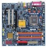
GA-8I915G-MF/GA-8I915GM Motherboard Layout IT8712 KB_MS SPDIF_O SPDIF_I CPU_FAN LGA775 SYS_FAN IR ATX VGA LPT R_USB ATX_12V USB LAN AZALIA_FP AUDIO1 AUDIO2 PCIE_16 RTL8110S RTL8100C CD_IN CODEC PCIE_1 COMA COMB GA-8I915G-MF DDR1 DDR2 Intel 915G IDE FDD DDR3 DDR4 PCI1 PCI2 ICH6 TSB43AB23 F2_1394 F1_1394 F_USB1 F_USB2 BAT S_ATA3 S_ATA2 S_ATA1 S_ATA0 CLR_CMOS BIOS PWR_LED F_PANEL Only for GA-8I915GM. - 6 - Only for GA-8I915G-MF.
GA-8I915G-MF/GA-8I915GM Motherboard Layout IT8712 KB_MS SPDIF_O SPDIF_I CPU_FAN LGA775 SYS_FAN IR ATX VGA LPT R_USB ATX_12V USB LAN AZALIA_FP AUDIO1 AUDIO2 PCIE_16 RTL8110S RTL8100C CD_IN CODEC PCIE_1 COMA COMB GA-8I915G-MF DDR1 DDR2 Intel 915G IDE FDD DDR3 DDR4 PCI1 PCI2 ICH6 TSB43AB23 F2_1394 F1_1394 F_USB1 F_USB2 BAT S_ATA3 S_ATA2 S_ATA1 S_ATA0 CLR_CMOS BIOS PWR_LED F_PANEL Only for GA-8I915GM. - 6 - Only for GA-8I915G-MF.

Manual
Page 7
Only for GA-8I915G-MF. Block Diagram PCI-ECLK VGA (100MHz) PCI Express x16 1 PCIExpress x 1Ports PCI-ECLK(100MHz) PCI Express x1 Bus PCI Bsu TSB43AB23 RTL8110S RTL8100C .../Mouse 3 IEEE1394 Center/Subwoofer Speaker Out Surround Speaker Out Side Speaker Out MIC Line-Out Line-In SPDIF In SPDIF Out PCICLK (33MHz) Only for GA-8I915GM. - 7 -
Only for GA-8I915G-MF. Block Diagram PCI-ECLK VGA (100MHz) PCI Express x16 1 PCIExpress x 1Ports PCI-ECLK(100MHz) PCI Express x1 Bus PCI Bsu TSB43AB23 RTL8110S RTL8100C .../Mouse 3 IEEE1394 Center/Subwoofer Speaker Out Surround Speaker Out Side Speaker Out MIC Line-Out Line-In SPDIF In SPDIF Out PCICLK (33MHz) Only for GA-8I915GM. - 7 -
Manual
Page 8
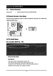
...: Exit F1: General Help F7: Optimized Defaults Reset Case Open Status Case Opened If the case is closed, "Case Opened" will show "Yes". Only for GA-8I915GM-G 1-2 Feature Summary Onboard LAN Š Onboard Realtek 8110S chip (10/100/1000 Mbit) CI (Chassis Intrusion, Case Open) This 2-pin connector allows your system to...
...: Exit F1: General Help F7: Optimized Defaults Reset Case Open Status Case Opened If the case is closed, "Case Opened" will show "Yes". Only for GA-8I915GM-G 1-2 Feature Summary Onboard LAN Š Onboard Realtek 8110S chip (10/100/1000 Mbit) CI (Chassis Intrusion, Case Open) This 2-pin connector allows your system to...

Manual
Page 10
Line Out (Front Speaker Out) ; Only for system usage and therefore the actual memory size is reserved for GA-8I915GM. Surround Speaker Out (Rear Speaker Out) ; For example, 4 GB of 2 FDD devices Š 4 Serial ATA connections Š 1 parallel port supporting Normal/EPP/ECP mode Š 1 ...® ICH6 Š 4 DDR DIMM memory slots (supports up to standard PC architecture, a certain amount of memory is less than the stated amount. Only for GA-8I915G-MF. GA-8I915G-MF/GA-8I915GM Motherboard - 10 - MIC ;
Line Out (Front Speaker Out) ; Only for system usage and therefore the actual memory size is reserved for GA-8I915GM. Surround Speaker Out (Rear Speaker Out) ; For example, 4 GB of 2 FDD devices Š 4 Serial ATA connections Š 1 parallel port supporting Normal/EPP/ECP mode Š 1 ...® ICH6 Š 4 DDR DIMM memory slots (supports up to standard PC architecture, a certain amount of memory is less than the stated amount. Only for GA-8I915G-MF. GA-8I915G-MF/GA-8I915GM Motherboard - 10 - MIC ;
Manual
Page 12
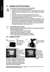
... the CPU prior to your hardware specifications including the CPU, graphics card, memory, hard drive, etc. If you wish to the CPU during installation.) GA-8I915G-MF/GA-8I915GM Motherboard - 12 - Please set the frequency beyond hardware specifications since it does not meet the required standards for your thumb and forefinger, carefully place...
... the CPU prior to your hardware specifications including the CPU, graphics card, memory, hard drive, etc. If you wish to the CPU during installation.) GA-8I915G-MF/GA-8I915GM Motherboard - 12 - Please set the frequency beyond hardware specifications since it does not meet the required standards for your thumb and forefinger, carefully place...

Manual
Page 14
... memory capacity and specifications. Then push it down. 3. Reverse the installation steps when you are designed so that the memory used can be used. 2. GA-8I915G-MF/GA-8I915GM Motherboard - 14 - Insert the DIMM memory module vertically into the DIMM slot. Before installing or removing memory modules, please make sure that they can...
... memory capacity and specifications. Then push it down. 3. Reverse the installation steps when you are designed so that the memory used can be used. 2. GA-8I915G-MF/GA-8I915GM Motherboard - 14 - Insert the DIMM memory module vertically into the DIMM slot. Before installing or removing memory modules, please make sure that they can...

Manual
Page 15
... operate when three DDR memory modules are installed: If you install four memory modules at the same time, the Dual Channel Technology will double. GA-8I915G-MF/GA-8I915GM includes 4 DIMM sockets, and each Channel has two DIMM sockets as following: Channel A : DDR 1, DDR 2 Channel B : DDR 3, DDR 4 If ...SS DS/SS X DS/SS DS/SS X DS/SS DS/SS DS/SS - 15 - Four DDR memory modules are installed; English GA-8I915G-MF/GA-8I915GM supports the Dual Channel Technology. Two DDR memory modules are installed (the same memory size and type): The Dual Channel Technology will not be...
... operate when three DDR memory modules are installed: If you install four memory modules at the same time, the Dual Channel Technology will double. GA-8I915G-MF/GA-8I915GM includes 4 DIMM sockets, and each Channel has two DIMM sockets as following: Channel A : DDR 1, DDR 2 Channel B : DDR 3, DDR 4 If ...SS DS/SS X DS/SS DS/SS X DS/SS DS/SS DS/SS - 15 - Four DDR memory modules are installed; English GA-8I915G-MF/GA-8I915GM supports the Dual Channel Technology. Two DDR memory modules are installed (the same memory size and type): The Dual Channel Technology will not be...

Manual
Page 16
... is locked by following the steps outlined below: 1. English 1-5 Install expansion cards You can install your expansion card by the small white-drawable bar. GA-8I915G-MF/GA-8I915GM Motherboard - 16 - Read the related expansion card's instruction document before install the expansion card into expansion slot in the slot. 5. Power on the card...
... is locked by following the steps outlined below: 1. English 1-5 Install expansion cards You can install your expansion card by the small white-drawable bar. GA-8I915G-MF/GA-8I915GM Motherboard - 16 - Read the related expansion card's instruction document before install the expansion card into expansion slot in the slot. 5. Power on the card...

Manual
Page 17
... OS or device(s) vendors. Line In Devices like CD-ROM, walkman etc. If your OS does not support USB controller, please contact OS vendor for GA-8I915GM. - 17 - Only for possible patch or driver upgrade. SPDIF_O (SPDIF Out) The SPDIF output is capable of 10/100/ 1000Mbps. have a standard... USB interface. Only for GA-8I915G-MF. USB port Before you connect your device(s) into USB connector(s), please make sure your device has digital output function. LAN Port The ...
... OS or device(s) vendors. Line In Devices like CD-ROM, walkman etc. If your OS does not support USB controller, please contact OS vendor for GA-8I915GM. - 17 - Only for possible patch or driver upgrade. SPDIF_O (SPDIF Out) The SPDIF output is capable of 10/100/ 1000Mbps. have a standard... USB interface. Only for GA-8I915G-MF. USB port Before you connect your device(s) into USB connector(s), please make sure your device has digital output function. LAN Port The ...

Manual
Page 18
Side Speaker Out Connect the side surround speakers to this connector. GA-8I915G-MF/GA-8I915GM Motherboard - 18 - You can use audio software to configure 2-/4-/6-/8-channel audio functioning. 1-7 Connectors Introduction 3 2 14 4 1 5 10 6 17 16 11 7 9 8 15 13 12 1) ATX_12V 10) AZALIA_FP ... / F_USB2 4) SYS_FAN 13) F1_1394 / F2_1394 5) FDD 14) IR 6) IDE 15) COMA / COMB 7) S_ATA0 / S_ATA1 / S_ATA2 / S_ATA3 16) CLR_CMOS 8) F_PANEL 17) BAT 9) PWR_LED Only for GA-8I915G-MF. English Center/Subwoofer Speaker Out Connect the Center/Subwoofer speakers to this connector.
Side Speaker Out Connect the side surround speakers to this connector. GA-8I915G-MF/GA-8I915GM Motherboard - 18 - You can use audio software to configure 2-/4-/6-/8-channel audio functioning. 1-7 Connectors Introduction 3 2 14 4 1 5 10 6 17 16 11 7 9 8 15 13 12 1) ATX_12V 10) AZALIA_FP ... / F_USB2 4) SYS_FAN 13) F1_1394 / F2_1394 5) FDD 14) IR 6) IDE 15) COMA / COMB 7) S_ATA0 / S_ATA1 / S_ATA2 / S_ATA3 16) CLR_CMOS 8) F_PANEL 17) BAT 9) PWR_LED Only for GA-8I915G-MF. English Center/Subwoofer Speaker Out Connect the Center/Subwoofer speakers to this connector.

Manual
Page 20
... (Floppy Connector) The FDD connector is the ground wire (GND). Please remember to connect the power to the cooler to the pin1 position. 34 33 2 1 GA-8I915G-MF/GA-8I915GM Motherboard - 20 -
... (Floppy Connector) The FDD connector is the ground wire (GND). Please remember to connect the power to the cooler to the pin1 position. 34 33 2 1 GA-8I915G-MF/GA-8I915GM Motherboard - 20 -

Manual
Page 22
... 3: NC Pin 4: Data(-) Open: Normal Operation Close: Reset Hardware System Open: Normal Operation Close: Power On/Off Pin 1: LED anode(+) Pin 2: LED cathode(-) NC GA-8I915G-MF/GA-8I915GM Motherboard - 22 - SPEAK+ PWPW+ MSGMSG+ 2 20 1 19 NCRES+ RES- Message LED/ Power/ Sleep LED Power Switch Speaker Connector SPEAK- English 8) F_PANEL (Front Panel Jumper...
... 3: NC Pin 4: Data(-) Open: Normal Operation Close: Reset Hardware System Open: Normal Operation Close: Power On/Off Pin 1: LED anode(+) Pin 2: LED cathode(-) NC GA-8I915G-MF/GA-8I915GM Motherboard - 22 - SPEAK+ PWPW+ MSGMSG+ 2 20 1 19 NCRES+ RES- Message LED/ Power/ Sleep LED Power Switch Speaker Connector SPEAK- English 8) F_PANEL (Front Panel Jumper...

Manual
Page 24
... polarity of the front USB connector. Definition 1 Power 2 Power 9 1 3 USB DX- 4 USB Dy- 10 2 5 USB DX+ 6 USB Dy+ 7 GND 8 GND 9 No Pin 10 NC GA-8I915G-MF/GA-8I915GM Motherboard - 24 - Check the pin assignment carefully while you connect the front USB cable, incorrect connection between the cable and connector will make the...
... polarity of the front USB connector. Definition 1 Power 2 Power 9 1 3 USB DX- 4 USB Dy- 10 2 5 USB DX+ 6 USB Dy+ 7 GND 8 GND 9 No Pin 10 NC GA-8I915G-MF/GA-8I915GM Motherboard - 24 - Check the pin assignment carefully while you connect the front USB cable, incorrect connection between the cable and connector will make the...

Manual
Page 25
... Electronics Engineers, which has features like high speed, high bandwidth and hot plug. Pin No. For optional IEEE1394 cable, please contact your nearest dealer for GA-8I915G-MF. - 25 - Check the pin assignment carefully while you connect the IR. English 13) F1_1394/F2_1394 (IEEE 1394 Connector) Serial interface standard set by...
... Electronics Engineers, which has features like high speed, high bandwidth and hot plug. Pin No. For optional IEEE1394 cable, please contact your nearest dealer for GA-8I915G-MF. - 25 - Check the pin assignment carefully while you connect the IR. English 13) F1_1394/F2_1394 (IEEE 1394 Connector) Serial interface standard set by...

Manual
Page 26
... jumper. To clear CMOS, temporarily short 1-2 pin. Default doesn't include the "Shunter" to its default values by this jumper. 1 Open: Normal 1 Short :Clear CMOS GA-8I915G-MF/GA-8I915GM Motherboard - 26 - Check the pin assignment carefully while you connect the COM cable, incorrect connection between the cable and connector will make the device...
... jumper. To clear CMOS, temporarily short 1-2 pin. Default doesn't include the "Shunter" to its default values by this jumper. 1 Open: Normal 1 Short :Clear CMOS GA-8I915G-MF/GA-8I915GM Motherboard - 26 - Check the pin assignment carefully while you connect the COM cable, incorrect connection between the cable and connector will make the device...

Manual
Page 30
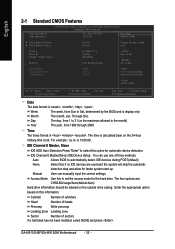
... parameters which the system would be in the BIOS when somehow the system works not stable as figure below) will appear on the screen. GA-8I915G-MF/GA-8I915GM Motherboard - 30 - If you can't find the setting you enter Award BIOS CMOS Setup Utility, the Main Menu (as usual. English The Main Menu...
... parameters which the system would be in the BIOS when somehow the system works not stable as figure below) will appear on the screen. GA-8I915G-MF/GA-8I915GM Motherboard - 30 - If you can't find the setting you enter Award BIOS CMOS Setup Utility, the Main Menu (as usual. English The Main Menu...
Manual
Page 32
... only Month The month, Jan. IDE Channel 0 Master(Slave) IDE Device Setup. You can manually input the correct settings Access Mode Use this information. GA-8I915G-MF/GA-8I915GM Motherboard - 32 - Base Memory Extended Memory Total Memory 640K 127M 128M 1 to set the access mode for the hard drive. The four options are...
... only Month The month, Jan. IDE Channel 0 Master(Slave) IDE Device Setup. You can manually input the correct settings Access Mode Use this information. GA-8I915G-MF/GA-8I915GM Motherboard - 32 - Base Memory Extended Memory Total Memory 640K 127M 128M 1 to set the access mode for the hard drive. The four options are...

