Manual
Page 3
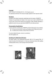
...any means without prior notice. The trademarks mentioned in this manual are legally registered to assist in the use of this product, GIGABYTE provides the following types of documentations: For quick set-up of this manual may be reproduced, copied, translated, ...All rights reserved. For product-related information, check on our website at: http://www.gigabyte.com Identifying Your Motherboard Revision The revision number on your motherboard revision before updating motherboard BIOS, drivers, or when looking for technical information. No part of the product, read the...
...any means without prior notice. The trademarks mentioned in this manual are legally registered to assist in the use of this product, GIGABYTE provides the following types of documentations: For quick set-up of this manual may be reproduced, copied, translated, ...All rights reserved. For product-related information, check on our website at: http://www.gigabyte.com Identifying Your Motherboard Revision The revision number on your motherboard revision before updating motherboard BIOS, drivers, or when looking for technical information. No part of the product, read the...
Manual
Page 4
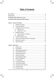
Table of Contents Box Contents...6 Optional Items...6 GA-880GM-USB3L Motherboard Layout 7 GA-880GM-USB3L Motherboard Block Diagram 8 Chapter 1 Hardware Installation 9 1-1 Installation Precautions 9 1-2 Product Specifications 10 1-3 Installing the CPU and CPU Cooler...8482; Configuration 19 1-7 Back Panel Connectors 20 1-8 Internal Connectors 22 Chapter 2 BIOS Setup 30 2-1 Startup Screen 31 2-2 The Main Menu 32 2-3 MB Intelligent Tweaker(M.I.T 34 2-4 Standard CMOS Features 40 2-5 Advanced BIOS Features 41 2-6 Integrated Peripherals 44 2-7 Power Management Setup 47 2-8 PnP/PCI ...
Table of Contents Box Contents...6 Optional Items...6 GA-880GM-USB3L Motherboard Layout 7 GA-880GM-USB3L Motherboard Block Diagram 8 Chapter 1 Hardware Installation 9 1-1 Installation Precautions 9 1-2 Product Specifications 10 1-3 Installing the CPU and CPU Cooler...8482; Configuration 19 1-7 Back Panel Connectors 20 1-8 Internal Connectors 22 Chapter 2 BIOS Setup 30 2-1 Startup Screen 31 2-2 The Main Menu 32 2-3 MB Intelligent Tweaker(M.I.T 34 2-4 Standard CMOS Features 40 2-5 Advanced BIOS Features 41 2-6 Integrated Peripherals 44 2-7 Power Management Setup 47 2-8 PnP/PCI ...

Manual
Page 5
... 57 3-4 Contact...58 3-5 System...58 3-6 Download Center 59 3-7 New Utilities...59 Chapter 4 Unique Features 60 4-1 Xpress Recovery2 60 4-2 BIOS Update Utilities 63 4-2-1 Updating the BIOS with the Q-Flash Utility 63 4-2-2 Updating the BIOS with the @BIOS Utility 66 4-3 EasyTune 6...67 4-4 Q-Share...68 4-5 SMART Recovery 69 4-6 Auto Green...70 4-7 Cloud OC...71 Chapter 5 Appendix...72...
... 57 3-4 Contact...58 3-5 System...58 3-6 Download Center 59 3-7 New Utilities...59 Chapter 4 Unique Features 60 4-1 Xpress Recovery2 60 4-2 BIOS Update Utilities 63 4-2-1 Updating the BIOS with the Q-Flash Utility 63 4-2-2 Updating the BIOS with the @BIOS Utility 66 4-3 EasyTune 6...67 4-4 Q-Share...68 4-5 SMART Recovery 69 4-6 Auto Green...70 4-7 Cloud OC...71 Chapter 5 Appendix...72...
Manual
Page 8
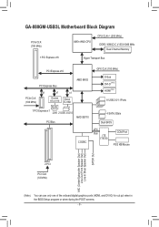
GA-880GM-USB3L Motherboard Block Diagram PCIe CLK (100 MHz) AM3+/AM3 CPU CPU CLK+/- (200 MHz) DDR3 1666(O.C.)/1333/1066 MHz Dual Channel Memory...Express x1 LAN 2 USB 3.0/2.0 PCI Bus AMD SB710 GFX CLK (100 MHz) D-Sub DVI-D (Note) HDMI(Note) 8 USB 2.0/1.1Ports 4 SATA 3Gb/s Dual BIOS CODEC LPC Bus iTE IT8720 COM Port PS/2 KB/Mouse MIC (Center/Subwoofer Speaker Out) Line-Out (Front Speaker Out) Line-In (Rear Speaker Out...) (Note) You can use only one of the onboard digital graphics ports (HDMI, and DVI-D) for out put when in the BIOS Setup program or when during the POST screens. - 8 -
GA-880GM-USB3L Motherboard Block Diagram PCIe CLK (100 MHz) AM3+/AM3 CPU CPU CLK+/- (200 MHz) DDR3 1666(O.C.)/1333/1066 MHz Dual Channel Memory...Express x1 LAN 2 USB 3.0/2.0 PCI Bus AMD SB710 GFX CLK (100 MHz) D-Sub DVI-D (Note) HDMI(Note) 8 USB 2.0/1.1Ports 4 SATA 3Gb/s Dual BIOS CODEC LPC Bus iTE IT8720 COM Port PS/2 KB/Mouse MIC (Center/Subwoofer Speaker Out) Line-Out (Front Speaker Out) Line-In (Rear Speaker Out...) (Note) You can use only one of the onboard digital graphics ports (HDMI, and DVI-D) for out put when in the BIOS Setup program or when during the POST screens. - 8 -

Manual
Page 12
...;Š 2 x 16 Mbit flash ŠŠ Use of licensed AWARD BIOS ŠŠ Support for DualBIOS™ ŠŠ PnP 1.0a, DMI 2.0, SM BIOS 2.4, ACPI 1.0b Unique Features ŠŠ Support for @BIOS ŠŠ Support for Q-Flash ŠŠ Support for Xpress BIOS Rescue ŠŠ Support for Download Center ŠŠ Support...
...;Š 2 x 16 Mbit flash ŠŠ Use of licensed AWARD BIOS ŠŠ Support for DualBIOS™ ŠŠ PnP 1.0a, DMI 2.0, SM BIOS 2.4, ACPI 1.0b Unique Features ŠŠ Support for @BIOS ŠŠ Support for Q-Flash ŠŠ Support for Xpress BIOS Rescue ŠŠ Support for Download Center ŠŠ Support...

Manual
Page 16
... will automatically detect the specifications and capacity of the memory. Hardware Installation - 16 - A memory module can be used . (Go to GIGABYTE's website for the latest supported memory speeds and memory modules.) • Always turn off the computer and unplug the power cord from the power...speed, and chips be installed in Dual Channel mode. 1. When enabling Dual Channel mode with two memory modules, it is installed, the BIOS will double the original memory bandwidth. After the memory is recommended that memory of the same capacity, brand, speed, and chips be enabled...
... will automatically detect the specifications and capacity of the memory. Hardware Installation - 16 - A memory module can be used . (Go to GIGABYTE's website for the latest supported memory speeds and memory modules.) • Always turn off the computer and unplug the power cord from the power...speed, and chips be installed in Dual Channel mode. 1. When enabling Dual Channel mode with two memory modules, it is installed, the BIOS will double the original memory bandwidth. After the memory is recommended that memory of the same capacity, brand, speed, and chips be enabled...
Manual
Page 18
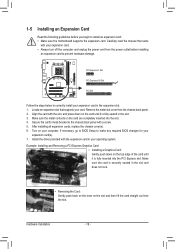
... an expansion card to prevent hardware damage. PCI Express x1 Slot PCI Express x16 Slot PCI Slot Follow the steps below to make any required BIOS changes for your expansion card in the slot and does not rock. • Removing the Card: Gently push back on the lever on the top... edge of the card until it is fully seated in your card. If necessary, go to BIOS Setup to correctly install your expansion card(s). 7. Align the card with the slot, and press down on the slot and then lift the card straight...
... an expansion card to prevent hardware damage. PCI Express x1 Slot PCI Express x16 Slot PCI Slot Follow the steps below to make any required BIOS changes for your expansion card in the slot and does not rock. • Removing the Card: Gently push back on the lever on the top... edge of the card until it is fully seated in your card. If necessary, go to BIOS Setup to correctly install your expansion card(s). 7. Align the card with the slot, and press down on the slot and then lift the card straight...
Manual
Page 19
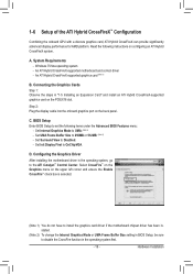
...UMA Frame Buffer Size to UMA. (Note 2) - Set Internal Graphics Mode to 256MB or 512MB. (Note 2) - Hardware Installation A. BIOS Setup Enter BIOS Setup to set the following instructions on the upper left corner and ensure the Enable CrossFire™ check box is selected. (Note 1)...an Expansion Card" and install an ATI Hybrid CrossFireX-supported graphics card on the back panel. Read the following items under the Advanced BIOS Features menu: - C. Set Init Display First to disable the CrossFire function in the operating system, go to Disabled. - Select CrossFire...
...UMA Frame Buffer Size to UMA. (Note 2) - Set Internal Graphics Mode to 256MB or 512MB. (Note 2) - Hardware Installation A. BIOS Setup Enter BIOS Setup to set the following instructions on the upper left corner and ensure the Enable CrossFire™ check box is selected. (Note 1)...an Expansion Card" and install an ATI Hybrid CrossFireX-supported graphics card on the back panel. Read the following items under the Advanced BIOS Features menu: - C. Set Init Display First to disable the CrossFire function in the operating system, go to Disabled. - Select CrossFire...
Manual
Page 21
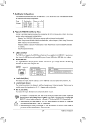
.... The table below . • Memory: Two 1 GB DDR3 1066 memory modules with dual channel mode enabled • BIOS Setup: At least 256 MB of UMA Frame Buffer Size (refer to Chapter 2, "BIOS Setup," "Advanced BIOS Features," for USB devices such as an optical drive, walkman, etc. Playback of the LAN port LEDs. Mic...
.... The table below . • Memory: Two 1 GB DDR3 1066 memory modules with dual channel mode enabled • BIOS Setup: At least 256 MB of UMA Frame Buffer Size (refer to Chapter 2, "BIOS Setup," "Advanced BIOS Features," for USB devices such as an optical drive, walkman, etc. Playback of the LAN port LEDs. Mic...
Manual
Page 24
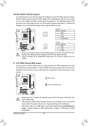
... the system may result in the correct orientation (the black connector wire is recommended that a system fan be sure to touch the two pins for BIOS configurations). Definition 1 GND 2 +12V 3 Sense 4 Speed Control 1 SYS_FAN SYS_FAN: Pin No. 3/4) CPU_FAN/SYS_FAN (Fan Headers) The motherboard has... • After clearing the CMOS values and before turning on the headers. 5) CLR_CMOS (Clearing CMOS Jumper) Use this jumper to Chapter 2, "BIOS Setup," for a few seconds. Most fan headers possess a foolproof insertion design. When connecting a fan cable, be installed inside the chassis. ...
... the system may result in the correct orientation (the black connector wire is recommended that a system fan be sure to touch the two pins for BIOS configurations). Definition 1 GND 2 +12V 3 Sense 4 Speed Control 1 SYS_FAN SYS_FAN: Pin No. 3/4) CPU_FAN/SYS_FAN (Fan Headers) The motherboard has... • After clearing the CMOS values and before turning on the headers. 5) CLR_CMOS (Clearing CMOS Jumper) Use this jumper to Chapter 2, "BIOS Setup," for a few seconds. Most fan headers possess a foolproof insertion design. When connecting a fan cable, be installed inside the chassis. ...

Manual
Page 25
... compatible with SATA 1.5Gb/s standard. the SATA cable to your SATA hard drive. 7) BAT(Battery) The battery provides power to keep the values (such as BIOS configurations, date, and time information) in the CMOS when the computer is replaced with an equivalent one minute. (Or use a metal object like a screwdriver to...
... compatible with SATA 1.5Gb/s standard. the SATA cable to your SATA hard drive. 7) BAT(Battery) The battery provides power to keep the values (such as BIOS configurations, date, and time information) in the CMOS when the computer is replaced with an equivalent one minute. (Or use a metal object like a screwdriver to...
Manual
Page 26
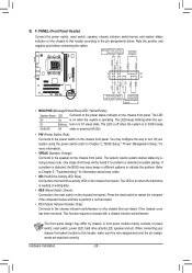
... switch, reset switch, power LED, hard drive activity LED, speaker and etc. When connecting your system using the power switch (refer to Chapter 2, "BIOS Setup," "Power Management Setup," for information about beep codes. • HD (Hard Drive Activity LED, Blue) Connects to the hard drive activity LED ...on the chassis front panel. S1 Blinking tem is detected, the BIOS may configure the way to turn off (S5). • PW (Power Switch, Red): Connects to the chassis intrusion switch/sensor on the chassis that...
... switch, reset switch, power LED, hard drive activity LED, speaker and etc. When connecting your system using the power switch (refer to Chapter 2, "BIOS Setup," "Power Management Setup," for information about beep codes. • HD (Hard Drive Activity LED, Blue) Connects to the hard drive activity LED ...on the chassis front panel. S1 Blinking tem is detected, the BIOS may configure the way to turn off (S5). • PW (Power Switch, Red): Connects to the chassis intrusion switch/sensor on the chassis that...
Manual
Page 29
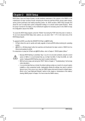
... Input and Output System) records hardware parameters of BIOS from the Internet and updates the BIOS. When the power is turned on the motherboard. To upgrade the BIOS, use either the GIGABYTE Q-Flash or @BIOS utility. • Q-Flash allows the user to the "Load Optimized Defaults" section in this occurs, try to clear the CMOS...
... Input and Output System) records hardware parameters of BIOS from the Internet and updates the BIOS. When the power is turned on the motherboard. To upgrade the BIOS, use either the GIGABYTE Q-Flash or @BIOS utility. • Q-Flash allows the user to the "Load Optimized Defaults" section in this occurs, try to clear the CMOS...
Manual
Page 30
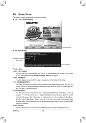
....00PG Copyright (C) 1984-2011, Award Software, Inc. After system restart, the device boot order will directly boot from the device configured in Boot Menu. BIOS Setup - 30 - GA-880GM-USB3L D11x . . . . : BIOS Setup : XpressRecovery2 : Boot Menu : Qflash 03/09/2011-RS880P-SB710-7A66BG0TC-00 Function Keys Function Keys: : POST SCREEN Press the key to show...
....00PG Copyright (C) 1984-2011, Award Software, Inc. After system restart, the device boot order will directly boot from the device configured in Boot Menu. BIOS Setup - 30 - GA-880GM-USB3L D11x . . . . : BIOS Setup : XpressRecovery2 : Boot Menu : Qflash 03/09/2011-RS880P-SB710-7A66BG0TC-00 Function Keys Function Keys: : POST SCREEN Press the key to show...

Manual
Page 31
... Without Saving ESC: Quit F8: Q-Flash Select Item F10: Save & Exit Setup Change CPU's Clock & Voltage F11: Save CMOS to BIOS F12: Load CMOS from BIOS Main Menu Help The on-screen description of a highlighted setup option is displayed on the bottom line of the submenu. • If you... CMOS to exit the help screen (General Help) of function keys available for reference only and may differ by BIOS version. - 31 - Press to BIOS Load CMOS from BIOS BIOS Setup Program Function Keys Move the selection bar to select an item Execute command or enter the submenu Main Menu:...
... Without Saving ESC: Quit F8: Q-Flash Select Item F10: Save & Exit Setup Change CPU's Clock & Voltage F11: Save CMOS to BIOS F12: Load CMOS from BIOS Main Menu Help The on-screen description of a highlighted setup option is displayed on the bottom line of the submenu. • If you... CMOS to exit the help screen (General Help) of function keys available for reference only and may differ by BIOS version. - 31 - Press to BIOS Load CMOS from BIOS BIOS Setup Program Function Keys Move the selection bar to select an item Execute command or enter the submenu Main Menu:...

Manual
Page 32
.../PCI Configurations Use this menu to configure the system's PCI & PnP resources. PC Health Status Use this function to load the BIOS settings from BIOS If your CPU, memory, etc. Standard CMOS Features Use this menu to configure the system time and date, hard drive types...; MB Intelligent Tweaker(M.I.T.) Use this menu to configure the clock, frequency and voltages of your system becomes unstable and you have loaded the BIOS default settings, you to restrict access to see information about autodetected system/CPU temperature, system voltage and fan speed, etc. Load...
.../PCI Configurations Use this menu to configure the system's PCI & PnP resources. PC Health Status Use this function to load the BIOS settings from BIOS If your CPU, memory, etc. Standard CMOS Features Use this menu to configure the system time and date, hard drive types...; MB Intelligent Tweaker(M.I.T.) Use this menu to configure the clock, frequency and voltages of your system becomes unstable and you have loaded the BIOS default settings, you to restrict access to see information about autodetected system/CPU temperature, system voltage and fan speed, etc. Load...

Manual
Page 33
... this occurs, clear the CMOS values and reset the board to default values.) • When the System Voltage Optimized item blinks in damage to boot. BIOS Setup
... this occurs, clear the CMOS values and reset the board to default values.) • When the System Voltage Optimized item blinks in damage to boot. BIOS Setup

Manual
Page 34
...output, depending on to which port the display device is connected, D-SUB/DVI-D or D-SUB/HDMI. BIOS Setup - 34 - This option is configurable only when Init Display First under Advanced BIOS Features is set to PEG and an ATI graphics card is installed. (Default: Disabled) Onboard VGA ...total amount of the onboard graphics output from 200 MHz to 2000 MHz. The adjustable range is set the VGA Core clock. Auto BIOS automatically determines the primary display port for the onboard graphics controller. IGX Configuration CMOS Setup Utility-Copyright (C) 1984-2011 Award Software IGX ...
...output, depending on to which port the display device is connected, D-SUB/DVI-D or D-SUB/HDMI. BIOS Setup - 34 - This option is configurable only when Init Display First under Advanced BIOS Features is set to PEG and an ATI graphics card is installed. (Default: Disabled) Onboard VGA ...total amount of the onboard graphics output from 200 MHz to 2000 MHz. The adjustable range is set the VGA Core clock. Auto BIOS automatically determines the primary display port for the onboard graphics controller. IGX Configuration CMOS Setup Utility-Copyright (C) 1984-2011 Award Software IGX ...

Manual
Page 35
... you to automatically adjust the CPU host frequency. The adjustable range is dependent on the CPU being used . Auto (default) allows the BIOS to alter the clock ratio for the installed CPU. Auto sets the PCIe clock frequency to standard 100 MHz. (Default: Auto) HT Link...determine whether to improve CPU performance. (Default: Disabled) CPU Host Clock Control Enables or disables the control of CPU host clock. Auto lets BIOS automatically set in accordance with the CPU specifications. The adjustable range is highly recommended that supports this feature. - 35 - Important It is ...
... you to automatically adjust the CPU host frequency. The adjustable range is dependent on the CPU being used . Auto (default) allows the BIOS to alter the clock ratio for the installed CPU. Auto sets the PCIe clock frequency to standard 100 MHz. (Default: Auto) HT Link...determine whether to improve CPU performance. (Default: Disabled) CPU Host Clock Control Enables or disables the control of CPU host clock. Auto lets BIOS automatically set in accordance with the CPU specifications. The adjustable range is highly recommended that supports this feature. - 35 - Important It is ...

Manual
Page 36
... you to set memory control mode. Minimum RAS Active Time Options are : Auto (default), 4T~7T. TwTr Command Delay Options are : Auto (default), 15T~30T. BIOS Setup - 36 - Options are: Auto (default), Manual. 1T/2T Command Timing Options are : Auto (default), 4T~12T. DRAM Configuration CMOS Setup Utility-Copyright (C) 1984-2011...
... you to set memory control mode. Minimum RAS Active Time Options are : Auto (default), 4T~7T. TwTr Command Delay Options are : Auto (default), 15T~30T. BIOS Setup - 36 - Options are: Auto (default), Manual. 1T/2T Command Timing Options are : Auto (default), 4T~12T. DRAM Configuration CMOS Setup Utility-Copyright (C) 1984-2011...


