Manual
Page 3
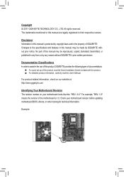
...the motherboard is 1.0. Copyright © 2011 GIGA-BYTE TECHNOLOGY CO., LTD. For example, "REV: 1.0" means the revision of GIGABYTE. Check your motherboard looks like this manual is protected by any means without prior notice. Changes to their respective owners. The ...manual may be made by GIGABYTE without GIGABYTE's prior written permission. Example: For product-related information, check on our website at: http://www.gigabyte.com Identifying Your Motherboard Revision The revision number on your motherboard revision before updating motherboard BIOS, drivers, or when looking ...
...the motherboard is 1.0. Copyright © 2011 GIGA-BYTE TECHNOLOGY CO., LTD. For example, "REV: 1.0" means the revision of GIGABYTE. Check your motherboard looks like this manual is protected by any means without prior notice. Changes to their respective owners. The ...manual may be made by GIGABYTE without GIGABYTE's prior written permission. Example: For product-related information, check on our website at: http://www.gigabyte.com Identifying Your Motherboard Revision The revision number on your motherboard revision before updating motherboard BIOS, drivers, or when looking ...
Manual
Page 4
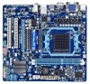
Table of Contents Box Contents...6 Optional Items...6 GA-880GM-USB3L Motherboard Layout 7 GA-880GM-USB3L Motherboard Block Diagram 8 Chapter 1 Hardware Installation 9 1-1 Installation Precautions 9 1-2 Product Specifications 10 1-3 Installing the CPU and CPU Cooler...8482; Configuration 19 1-7 Back Panel Connectors 20 1-8 Internal Connectors 22 Chapter 2 BIOS Setup 30 2-1 Startup Screen 31 2-2 The Main Menu 32 2-3 MB Intelligent Tweaker(M.I.T 34 2-4 Standard CMOS Features 40 2-5 Advanced BIOS Features 41 2-6 Integrated Peripherals 44 2-7 Power Management Setup 47 2-8 PnP/PCI ...
Table of Contents Box Contents...6 Optional Items...6 GA-880GM-USB3L Motherboard Layout 7 GA-880GM-USB3L Motherboard Block Diagram 8 Chapter 1 Hardware Installation 9 1-1 Installation Precautions 9 1-2 Product Specifications 10 1-3 Installing the CPU and CPU Cooler...8482; Configuration 19 1-7 Back Panel Connectors 20 1-8 Internal Connectors 22 Chapter 2 BIOS Setup 30 2-1 Startup Screen 31 2-2 The Main Menu 32 2-3 MB Intelligent Tweaker(M.I.T 34 2-4 Standard CMOS Features 40 2-5 Advanced BIOS Features 41 2-6 Integrated Peripherals 44 2-7 Power Management Setup 47 2-8 PnP/PCI ...

Manual
Page 5
... 57 3-4 Contact...58 3-5 System...58 3-6 Download Center 59 3-7 New Utilities...59 Chapter 4 Unique Features 60 4-1 Xpress Recovery2 60 4-2 BIOS Update Utilities 63 4-2-1 Updating the BIOS with the Q-Flash Utility 63 4-2-2 Updating the BIOS with the @BIOS Utility 66 4-3 EasyTune 6...67 4-4 Q-Share...68 4-5 SMART Recovery 69 4-6 Auto Green...70 4-7 Cloud OC...71 Chapter 5 Appendix...72...
... 57 3-4 Contact...58 3-5 System...58 3-6 Download Center 59 3-7 New Utilities...59 Chapter 4 Unique Features 60 4-1 Xpress Recovery2 60 4-2 BIOS Update Utilities 63 4-2-1 Updating the BIOS with the Q-Flash Utility 63 4-2-2 Updating the BIOS with the @BIOS Utility 66 4-3 EasyTune 6...67 4-4 Q-Share...68 4-5 SMART Recovery 69 4-6 Auto Green...70 4-7 Cloud OC...71 Chapter 5 Appendix...72...
Manual
Page 8
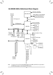
GA-880GM-USB3L Motherboard Block Diagram PCIe CLK (100 MHz) AM3+/AM3 CPU CPU CLK+/- (200 MHz) DDR3 1666(O.C.)/1333/1066 MHz Dual Channel Memory...Express x1 LAN 2 USB 3.0/2.0 PCI Bus AMD SB710 GFX CLK (100 MHz) D-Sub DVI-D (Note) HDMI(Note) 8 USB 2.0/1.1Ports 4 SATA 3Gb/s Dual BIOS CODEC LPC Bus iTE IT8720 COM Port PS/2 KB/Mouse MIC (Center/Subwoofer Speaker Out) Line-Out (Front Speaker Out) Line-In (Rear Speaker Out...) (Note) You can use only one of the onboard digital graphics ports (HDMI, and DVI-D) for out put when in the BIOS Setup program or when during the POST screens. - 8 -
GA-880GM-USB3L Motherboard Block Diagram PCIe CLK (100 MHz) AM3+/AM3 CPU CPU CLK+/- (200 MHz) DDR3 1666(O.C.)/1333/1066 MHz Dual Channel Memory...Express x1 LAN 2 USB 3.0/2.0 PCI Bus AMD SB710 GFX CLK (100 MHz) D-Sub DVI-D (Note) HDMI(Note) 8 USB 2.0/1.1Ports 4 SATA 3Gb/s Dual BIOS CODEC LPC Bus iTE IT8720 COM Port PS/2 KB/Mouse MIC (Center/Subwoofer Speaker Out) Line-Out (Front Speaker Out) Line-In (Rear Speaker Out...) (Note) You can use only one of the onboard digital graphics ports (HDMI, and DVI-D) for out put when in the BIOS Setup program or when during the POST screens. - 8 -

Manual
Page 12
...; 2 x 16 Mbit flash ŠŠ Use of licensed AWARD BIOS ŠŠ Support for DualBIOS™ ŠŠ PnP 1.0a, DMI 2.0, SM BIOS 2.4, ACPI 1.0b Unique Features ŠŠ Support for @BIOS ŠŠ Support for Q-Flash ŠŠ Support for Xpress BIOS Rescue ŠŠ Support for Download Center ŠŠ Support for...
...; 2 x 16 Mbit flash ŠŠ Use of licensed AWARD BIOS ŠŠ Support for DualBIOS™ ŠŠ PnP 1.0a, DMI 2.0, SM BIOS 2.4, ACPI 1.0b Unique Features ŠŠ Support for @BIOS ŠŠ Support for Q-Flash ŠŠ Support for Xpress BIOS Rescue ŠŠ Support for Download Center ŠŠ Support for...

Manual
Page 16
...and supports Dual Channel Technology. Dual Channel mode cannot be installed in Dual Channel mode. 1. After the memory is installed, the BIOS will double the original memory bandwidth. Hardware Installation - 16 - Enabling Dual Channel memory mode will automatically detect the specifications and capacity... of the same capacity, brand, speed, and chips be used . (Go to GIGABYTE's website for the latest supported memory speeds and memory modules.) • Always turn off the computer and unplug the power cord from ...
...and supports Dual Channel Technology. Dual Channel mode cannot be installed in Dual Channel mode. 1. After the memory is installed, the BIOS will double the original memory bandwidth. Hardware Installation - 16 - Enabling Dual Channel memory mode will automatically detect the specifications and capacity... of the same capacity, brand, speed, and chips be used . (Go to GIGABYTE's website for the latest supported memory speeds and memory modules.) • Always turn off the computer and unplug the power cord from ...
Manual
Page 18
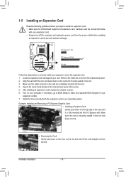
... with the slot, and press down on the slot and then lift the card straight out from the slot. If necessary, go to BIOS Setup to make any required BIOS changes for your computer. Example: Installing and Removing a PCI Express Graphics Card: • Installing a Graphics Card: Gently push down on the card...
... with the slot, and press down on the slot and then lift the card straight out from the slot. If necessary, go to BIOS Setup to make any required BIOS changes for your computer. Example: Installing and Removing a PCI Express Graphics Card: • Installing a Graphics Card: Gently push down on the card...
Manual
Page 19
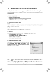
... if the motherboard chipset driver has been installed. (Note 2) To change the Internal Graphics Mode or UMA Frame Buffer Size setting in BIOS Setup, be sure to the ATI Catalyst™ Control Center. Set Init Display First to UMA. (Note 2) - Hardware Installation Read... the following items under the Advanced BIOS Features menu: - Set Internal Graphics Mode to OnChipVGA. D. A. System Requirements - Connecting the Graphics Cards Step 1: Observe the steps in the ...
... if the motherboard chipset driver has been installed. (Note 2) To change the Internal Graphics Mode or UMA Frame Buffer Size setting in BIOS Setup, be sure to the ATI Catalyst™ Control Center. Set Init Display First to UMA. (Note 2) - Hardware Installation Read... the following items under the Advanced BIOS Features menu: - Set Internal Graphics Mode to OnChipVGA. D. A. System Requirements - Connecting the Graphics Cards Step 1: Observe the steps in the ...
Manual
Page 21
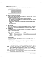
The table below . • Memory: Two 1 GB DDR3 1066 memory modules with dual channel mode enabled • BIOS Setup: At least 256 MB of UMA Frame Buffer Size (refer to Chapter 2, "BIOS Setup," "Advanced BIOS Features," for video output: DVI-D, HDMI and D-Sub. Use this port for a headphone or 2-channel speaker. Line Out Jack...
The table below . • Memory: Two 1 GB DDR3 1066 memory modules with dual channel mode enabled • BIOS Setup: At least 256 MB of UMA Frame Buffer Size (refer to Chapter 2, "BIOS Setup," "Advanced BIOS Features," for video output: DVI-D, HDMI and D-Sub. Use this port for a headphone or 2-channel speaker. Line Out Jack...
Manual
Page 24
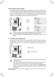
... Overheating may result in the correct orientation (the black connector wire is recommended that a system fan be sure to touch the two pins for BIOS configurations). Do not place a jumper cap on your computer, be installed inside the chassis. 1 CPU_FAN CPU_FAN: Pin No. To clear the ... to connect it is the ground wire). Definition 1 GND 2 +12V 3 Sense 4 Speed Control 1 SYS_FAN SYS_FAN: Pin No. date information and BIOS configurations) and reset the CMOS values to prevent your computer and unplug the power cord from the power outlet before clearing the CMOS values. •...
... Overheating may result in the correct orientation (the black connector wire is recommended that a system fan be sure to touch the two pins for BIOS configurations). Do not place a jumper cap on your computer, be installed inside the chassis. 1 CPU_FAN CPU_FAN: Pin No. To clear the ... to connect it is the ground wire). Definition 1 GND 2 +12V 3 Sense 4 Speed Control 1 SYS_FAN SYS_FAN: Pin No. date information and BIOS configurations) and reset the CMOS values to prevent your computer and unplug the power cord from the power outlet before clearing the CMOS values. •...

Manual
Page 25
... - Danger of explosion if the battery is turned off your SATA hard drive. 7) BAT(Battery) The battery provides power to keep the values (such as BIOS configurations, date, and time information) in accordance with an incorrect model. • Contact the place of purchase or local dealer if you are not able...
... - Danger of explosion if the battery is turned off your SATA hard drive. 7) BAT(Battery) The battery provides power to keep the values (such as BIOS configurations, date, and time information) in accordance with an incorrect model. • Contact the place of purchase or local dealer if you are not able...
Manual
Page 26
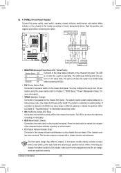
... on the chassis front panel. The LED keeps blinking when the sys- The LED is on when the hard drive is detected, the BIOS may issue beeps in S1 sleep state. The front panel design may configure the way to turn off your chassis front panel module to ... 2 20 1 19 HD+ HD- Message/Power/ Power Sleep LED Switch Speaker MSG+ MSG- When connecting your system using the power switch (refer to Chapter 2, "BIOS Setup," "Power Management Setup," for information about beep codes. • HD (Hard Drive Activity LED, Blue) Connects to the power status indicator on the chassis...
... on the chassis front panel. The LED keeps blinking when the sys- The LED is on when the hard drive is detected, the BIOS may issue beeps in S1 sleep state. The front panel design may configure the way to turn off your chassis front panel module to ... 2 20 1 19 HD+ HD- Message/Power/ Power Sleep LED Switch Speaker MSG+ MSG- When connecting your system using the power switch (refer to Chapter 2, "BIOS Setup," "Power Management Setup," for information about beep codes. • HD (Hard Drive Activity LED, Blue) Connects to the power status indicator on the chassis...
Manual
Page 29
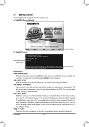
...power is turned off, the battery on . To see more advanced BIOS Setup menu options, you can press + in the main menu of BIOS from the Internet and updates the BIOS. To upgrade the BIOS, use either the GIGABYTE Q-Flash or @BIOS utility. • Q-Flash allows the user to quickly and easily... upgrade or back up BIOS without entering the operating system. • @BIOS is recommended that you not alter ...
...power is turned off, the battery on . To see more advanced BIOS Setup menu options, you can press + in the main menu of BIOS from the Internet and updates the BIOS. To upgrade the BIOS, use either the GIGABYTE Q-Flash or @BIOS utility. • Q-Flash allows the user to quickly and easily... upgrade or back up BIOS without entering the operating system. • @BIOS is recommended that you not alter ...
Manual
Page 30
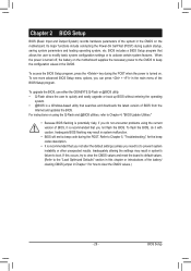
... ever entered Xpress Recovery2 to back up arrow key or the down arrow key to select the first boot device, then press to accept. BIOS Setup - 30 - GA-880GM-USB3L D11x . . . . : BIOS Setup : XpressRecovery2 : Boot Menu : Qflash 03/09/2011-RS880P-SB710-7A66BG0TC-00 Function Keys Function Keys: : POST SCREEN Press the key to set...
... ever entered Xpress Recovery2 to back up arrow key or the down arrow key to select the first boot device, then press to accept. BIOS Setup - 30 - GA-880GM-USB3L D11x . . . . : BIOS Setup : XpressRecovery2 : Boot Menu : Qflash 03/09/2011-RS880P-SB710-7A66BG0TC-00 Function Keys Function Keys: : POST SCREEN Press the key to set...

Manual
Page 31
... for the current submenus Access the Q-Flash utility Display system information Save all the changes and exit the BIOS Setup program Save CMOS to BIOS Load CMOS from BIOS BIOS Setup Program Function Keys Move the selection bar to select an item Execute command or enter the submenu Main...Saving ESC: Quit F8: Q-Flash Select Item F10: Save & Exit Setup Change CPU's Clock & Voltage F11: Save CMOS to BIOS F12: Load CMOS from BIOS Main Menu Help The on-screen description of a highlighted setup option is displayed on the bottom line of function keys available for ...
... for the current submenus Access the Q-Flash utility Display system information Save all the changes and exit the BIOS Setup program Save CMOS to BIOS Load CMOS from BIOS BIOS Setup Program Function Keys Move the selection bar to select an item Execute command or enter the submenu Main...Saving ESC: Quit F8: Q-Flash Select Item F10: Save & Exit Setup Change CPU's Clock & Voltage F11: Save CMOS to BIOS F12: Load CMOS from BIOS Main Menu Help The on-screen description of a highlighted setup option is displayed on the bottom line of function keys available for ...

Manual
Page 32
...saving functions. PnP/PCI Configurations Use this menu to configure the system's PCI & PnP resources. PC Health Status Use this task.) BIOS Setup - 32 - You can use the SPACE key) and then press to complete. F12: Load CMOS from a profile created before, ...without the hassles of errors that stop the system boot, etc. Advanced BIOS Features Use this menu to configure the device boot order, advanced features available on the CPU, and the primary display adapter. Integrated Peripherals...
...saving functions. PnP/PCI Configurations Use this menu to configure the system's PCI & PnP resources. PC Health Status Use this task.) BIOS Setup - 32 - You can use the SPACE key) and then press to complete. F12: Load CMOS from a profile created before, ...without the hassles of errors that stop the system boot, etc. Advanced BIOS Features Use this menu to configure the device boot order, advanced features available on the CPU, and the primary display adapter. Integrated Peripherals...

Manual
Page 33
... occurs, clear the CMOS values and reset the board to default values.) • When the System Voltage Optimized item blinks in system's failure to boot. BIOS Setup 2-3 MB Intelligent Tweaker(M.I.T.) CMOS Setup Utility-Copyright (C) 1984-2011 Award Software MB Intelligent Tweaker(M.I .T.) x CPU NB VID Control x CPU Voltage Control Normal CPU Vcore...
... occurs, clear the CMOS values and reset the board to default values.) • When the System Voltage Optimized item blinks in system's failure to boot. BIOS Setup 2-3 MB Intelligent Tweaker(M.I.T.) CMOS Setup Utility-Copyright (C) 1984-2011 Award Software MB Intelligent Tweaker(M.I .T.) x CPU NB VID Control x CPU Voltage Control Normal CPU Vcore...

Manual
Page 34
... F7: Optimized Defaults Internal Graphics Mode Allows you to manually set to PEG and an ATI graphics card is set the VGA Core clock. Auto BIOS automatically determines the primary display port for output, depending on to which port the display device is from the D-SUB/DVI-D or D-SUB/HDMI. The... View Enables or disables the Surround View function. Disabled Disables the onboard graphics controller. This option is configurable only when Init Display First under Advanced BIOS Features is set to Manual...
... F7: Optimized Defaults Internal Graphics Mode Allows you to manually set to PEG and an ATI graphics card is set the VGA Core clock. Auto BIOS automatically determines the primary display port for output, depending on to which port the display device is from the D-SUB/DVI-D or D-SUB/HDMI. The... View Enables or disables the Surround View function. Disabled Disables the onboard graphics controller. This option is configurable only when Init Display First under Advanced BIOS Features is set to Manual...

Manual
Page 35
...(MHz) Allows you to manually set in accordance with the CPU specifications. HT Link Frequency Allows you to manually set the CPU host frequency. Auto BIOS will automatically adjust the HT Link Width. (Default) 8 bit Sets HT Link Width to 8 bit. 16 bit Sets HT Link Width to 16.... (Default: Auto) Memory Clock This option is configurable only when Set Memory Clock is highly recommended that supports this feature. - 35 - Auto BIOS will automatically adjust the HT Link Frequency. (Default) x1~x10 Sets HT Link Frequency to manually set the memory clock as required. Auto lets...
...(MHz) Allows you to manually set in accordance with the CPU specifications. HT Link Frequency Allows you to manually set the CPU host frequency. Auto BIOS will automatically adjust the HT Link Width. (Default) 8 bit Sets HT Link Width to 8 bit. 16 bit Sets HT Link Width to 16.... (Default: Auto) Memory Clock This option is configurable only when Set Memory Clock is highly recommended that supports this feature. - 35 - Auto BIOS will automatically adjust the HT Link Frequency. (Default) x1~x10 Sets HT Link Frequency to manually set the memory clock as required. Auto lets...

Manual
Page 36
... Recovery Time Options are : Auto (default), 1T, 2T. CAS# latency Options are : Auto (default), 5T~12T. Row Precharge Time Options are : Auto (default), 4T~12T. BIOS Setup - 36 - Minimum RAS Active Time Options are : Auto (default), 4T~7T. Ganged Sets memory control mode to be configurable. RAS to set memory control...
... Recovery Time Options are : Auto (default), 1T, 2T. CAS# latency Options are : Auto (default), 5T~12T. Row Precharge Time Options are : Auto (default), 4T~12T. BIOS Setup - 36 - Minimum RAS Active Time Options are : Auto (default), 4T~7T. Ganged Sets memory control mode to be configurable. RAS to set memory control...


