Manual
Page 3
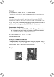
.... For product-related information, check on our website at: http://www.gigabyte.com.tw Identifying Your Motherboard Revision The revision number on your motherboard revision before updating motherboard BIOS, drivers, or when looking for technical information. Check your motherboard looks ...like this manual may be made by any form or by GIGABYTE without GIGABYTE's prior written permission. For example, "REV: ...
.... For product-related information, check on our website at: http://www.gigabyte.com.tw Identifying Your Motherboard Revision The revision number on your motherboard revision before updating motherboard BIOS, drivers, or when looking for technical information. Check your motherboard looks ...like this manual may be made by any form or by GIGABYTE without GIGABYTE's prior written permission. For example, "REV: ...
Manual
Page 4
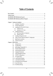
Table of Contents Box Contents...6 Optional Items...6 GA-880GM-USB3 Motherboard Layout 7 GA-880GM-USB3 Motherboard Block Diagram 8 Chapter 1 Hardware Installation 9 1-1 Installation Precautions 9 1-2 Product Specifications 10 1-3 Installing the CPU and CPU Cooler...8482; Configuration 19 1-7 Back Panel Connectors 20 1-8 Internal Connectors 23 Chapter 2 BIOS Setup 31 2-1 Startup Screen 32 2-2 The Main Menu 34 2-3 MB Intelligent Tweaker(M.I.T 36 2-4 Standard CMOS Features 41 2-5 Advanced BIOS Features 43 2-6 Integrated Peripherals 46 2-7 Power Management Setup 49 2-8 PnP/PCI ...
Table of Contents Box Contents...6 Optional Items...6 GA-880GM-USB3 Motherboard Layout 7 GA-880GM-USB3 Motherboard Block Diagram 8 Chapter 1 Hardware Installation 9 1-1 Installation Precautions 9 1-2 Product Specifications 10 1-3 Installing the CPU and CPU Cooler...8482; Configuration 19 1-7 Back Panel Connectors 20 1-8 Internal Connectors 23 Chapter 2 BIOS Setup 31 2-1 Startup Screen 32 2-2 The Main Menu 34 2-3 MB Intelligent Tweaker(M.I.T 36 2-4 Standard CMOS Features 41 2-5 Advanced BIOS Features 43 2-6 Integrated Peripherals 46 2-7 Power Management Setup 49 2-8 PnP/PCI ...
Manual
Page 5
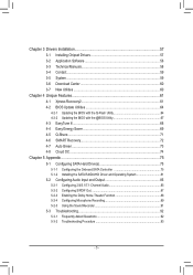
... 58 3-4 Contact...59 3-5 System...59 3-6 Download Center 60 3-7 New Utilities...60 Chapter 4 Unique Features 61 4-1 Xpress Recovery2 61 4-2 BIOS Update Utilities 64 4-2-1 Updating the BIOS with the Q-Flash Utility 64 4-2-2 Updating the BIOS with the @BIOS Utility 67 4-3 EasyTune 6...68 4-4 Easy Energy Saver 69 4-5 Q-Share...71 4-6 SMART Recovery 72 4-7 Auto Green...73 4-8 Cloud OC...
... 58 3-4 Contact...59 3-5 System...59 3-6 Download Center 60 3-7 New Utilities...60 Chapter 4 Unique Features 61 4-1 Xpress Recovery2 61 4-2 BIOS Update Utilities 64 4-2-1 Updating the BIOS with the Q-Flash Utility 64 4-2-2 Updating the BIOS with the @BIOS Utility 67 4-3 EasyTune 6...68 4-4 Easy Energy Saver 69 4-5 Q-Share...71 4-6 SMART Recovery 72 4-7 Auto Green...73 4-8 Cloud OC...
Manual
Page 8
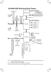
GA-880GM-USB3 Motherboard Block Diagram 1 PCI Express x16 PCIe CLK (100 MHz) LAN RJ45 AM3+/AM3 CPU CPU CLK+/- (200 MHz) DDR3 1800 (O.C.) (Note 1)/ 1333/1066 MHz ... D-Sub DVI-D (Note 2) PCIe CLK (100 MHz) 1 PCI Express x1 HDMI (Note 2) 6 SATA 3Gb/s PCI Bus TSB43AB23 2 IEEE 1394a 10 USB Ports AMD SB710 Dual BIOS LPC Bus iTE IT8720 CODEC COM Port PS/2 KB/Mouse Surround Speaker Out Center/Subwoofer Speaker Out Side Speaker Out MIC Line Out Line In...
GA-880GM-USB3 Motherboard Block Diagram 1 PCI Express x16 PCIe CLK (100 MHz) LAN RJ45 AM3+/AM3 CPU CPU CLK+/- (200 MHz) DDR3 1800 (O.C.) (Note 1)/ 1333/1066 MHz ... D-Sub DVI-D (Note 2) PCIe CLK (100 MHz) 1 PCI Express x1 HDMI (Note 2) 6 SATA 3Gb/s PCI Bus TSB43AB23 2 IEEE 1394a 10 USB Ports AMD SB710 Dual BIOS LPC Bus iTE IT8720 CODEC COM Port PS/2 KB/Mouse Surround Speaker Out Center/Subwoofer Speaker Out Side Speaker Out MIC Line Out Line In...

Manual
Page 12
...; 2 x 16 Mbit flash ŠŠ Use of licensed AWARD BIOS ŠŠ Support for DualBIOS™ ŠŠ PnP 1.0a, DMI 2.0, SM BIOS 2.4, ACPI 1.0b Unique Features ŠŠ Support for @BIOS ŠŠ Support for Q-Flash ŠŠ Support for Xpress BIOS Rescue ŠŠ Support for Download Center ŠŠ Support for...
...; 2 x 16 Mbit flash ŠŠ Use of licensed AWARD BIOS ŠŠ Support for DualBIOS™ ŠŠ PnP 1.0a, DMI 2.0, SM BIOS 2.4, ACPI 1.0b Unique Features ŠŠ Support for @BIOS ŠŠ Support for Q-Flash ŠŠ Support for Xpress BIOS Rescue ŠŠ Support for Download Center ŠŠ Support for...
Manual
Page 16
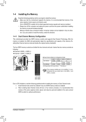
... memory of the same capacity, brand, speed, and chips be enabled if only one direction. Dual Channel mode cannot be used . (Go to GIGABYTE's website for optimum performance. After the memory is installed. 2. Enabling Dual Channel memory mode will automatically detect the specifications and capacity of the same ...capacity, brand, speed, and chips be installed in only one DDR3 memory module is installed, the BIOS will double the original memory bandwidth. DS/SS DS/SS Four Modules DS/SS DS/SS DS/SS DS/SS (SS=Single-Sided, DS...
... memory of the same capacity, brand, speed, and chips be enabled if only one direction. Dual Channel mode cannot be used . (Go to GIGABYTE's website for optimum performance. After the memory is installed. 2. Enabling Dual Channel memory mode will automatically detect the specifications and capacity of the same ...capacity, brand, speed, and chips be installed in only one DDR3 memory module is installed, the BIOS will double the original memory bandwidth. DS/SS DS/SS Four Modules DS/SS DS/SS DS/SS DS/SS (SS=Single-Sided, DS...
Manual
Page 18
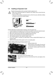
... back panel. 2. Make sure the metal contacts on the card until it is fully seated in the slot. 3. If necessary, go to BIOS Setup to make any required BIOS changes for your expansion card in the expansion slot. 1. Install the driver provided with your operating system. Locate an expansion slot that came...
... back panel. 2. Make sure the metal contacts on the card until it is fully seated in the slot. 3. If necessary, go to BIOS Setup to make any required BIOS changes for your expansion card in the expansion slot. 1. Install the driver provided with your operating system. Locate an expansion slot that came...
Manual
Page 19
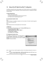
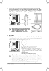
... 2) To change the Internal Graphics Mode or UMA Frame Buffer Size setting in BIOS Setup, be sure to disable the CrossFire function in the operating system, go to UMA. (Note 2) - C. BIOS Setup Enter BIOS Setup to Disabled. - Step 2: Plug the display cable into the onboard graphics...Hybrid CrossFireX system. Set Internal Graphics Mode to the ATI Catalyst™ Control Center. Read the following items under the Advanced BIOS Features menu: - An ATI Hybrid CrossFireX-supported motherboard and correct driver - Set Surround View to set the following instructions on the back...
... 2) To change the Internal Graphics Mode or UMA Frame Buffer Size setting in BIOS Setup, be sure to disable the CrossFire function in the operating system, go to UMA. (Note 2) - C. BIOS Setup Enter BIOS Setup to Disabled. - Step 2: Plug the display cable into the onboard graphics...Hybrid CrossFireX system. Set Internal Graphics Mode to the ATI Catalyst™ Control Center. Read the following items under the Advanced BIOS Features menu: - An ATI Hybrid CrossFireX-supported motherboard and correct driver - Set Surround View to set the following instructions on the back...
Manual
Page 21
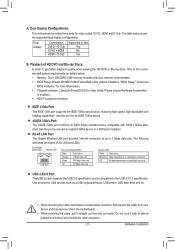
...Port The Gigabit Ethernet LAN port provides Internet connection at up to SATA 3Gb/s standard and is compatible with dual channel mode enabled • BIOS Setup: At least 256 MB of the LAN port LEDs. Use this port for video output: DVI-D, HDMI and D-Sub. eSATA 3Gb... short inside the cable connector. - 21 - Hardware Installation The following describes the states of UMA Frame Buffer Size (refer to Chapter 2, "BIOS Setup," "Advanced BIOS Features," for USB devices such as a USB keyboard/mouse, USB printer, USB flash drive and etc. • When removing the cable connected...
...Port The Gigabit Ethernet LAN port provides Internet connection at up to SATA 3Gb/s standard and is compatible with dual channel mode enabled • BIOS Setup: At least 256 MB of the LAN port LEDs. Use this port for video output: DVI-D, HDMI and D-Sub. eSATA 3Gb... short inside the cable connector. - 21 - Hardware Installation The following describes the states of UMA Frame Buffer Size (refer to Chapter 2, "BIOS Setup," "Advanced BIOS Features," for USB devices such as a USB keyboard/mouse, USB printer, USB flash drive and etc. • When removing the cable connected...
Manual
Page 25
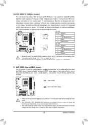
...Pin No. Do not place a jumper cap on the two pins to clear the CMOS values (e.g. date information and BIOS configurations) and reset the CMOS values to touch the two pins for BIOS configurations). - 25 - To clear the CMOS values, place a jumper cap on the headers. 5) CLR_CMOS (Clearing ...Control 3 Sense 4 Reserve •• Be sure to connect fan cables to the fan headers to prevent your computer, be sure to Chapter 2, "BIOS Setup," for a few seconds. The black connector wire is recommended that a system fan be installed inside the chassis. For optimum heat dissipation, it ...
...Pin No. Do not place a jumper cap on the two pins to clear the CMOS values (e.g. date information and BIOS configurations) and reset the CMOS values to touch the two pins for BIOS configurations). - 25 - To clear the CMOS values, place a jumper cap on the headers. 5) CLR_CMOS (Clearing ...Control 3 Sense 4 Reserve •• Be sure to connect fan cables to the fan headers to prevent your computer, be sure to Chapter 2, "BIOS Setup," for a few seconds. The black connector wire is recommended that a system fan be installed inside the chassis. For optimum heat dissipation, it ...
Manual
Page 26
... cord and restart your computer. • Always turn off your SATA hard drive. 7) BAT (Battery) The battery provides power to keep the values (such as BIOS configurations, date, and time information) in accordance with an equivalent one minute. (Or use a metal object like a screwdriver to touch the positive and negative terminals...
... cord and restart your computer. • Always turn off your SATA hard drive. 7) BAT (Battery) The battery provides power to keep the values (such as BIOS configurations, date, and time information) in accordance with an equivalent one minute. (Or use a metal object like a screwdriver to touch the positive and negative terminals...

Manual
Page 27
...chassis front panel module to this header according to the pin assignments below. When connecting your system using the power switch (refer to Chapter 2, "BIOS Setup," "Power Management Setup," for information about beep codes. • HD (Hard Drive Activity LED, Blue) Connects to the hard drive activity...S0 On is on when the system is in different patterns to indicate the problem. The LED is off when the system is detected, the BIOS may differ by issuing a beep code. 8) F_PANEL (Front Panel Header) Connect the power switch, reset switch, speaker, chassis intrusion switch/sensor...
...chassis front panel module to this header according to the pin assignments below. When connecting your system using the power switch (refer to Chapter 2, "BIOS Setup," "Power Management Setup," for information about beep codes. • HD (Hard Drive Activity LED, Blue) Connects to the hard drive activity...S0 On is on when the system is in different patterns to indicate the problem. The LED is off when the system is detected, the BIOS may differ by issuing a beep code. 8) F_PANEL (Front Panel Header) Connect the power switch, reset switch, speaker, chassis intrusion switch/sensor...

Manual
Page 31
... configuration settings or to boot. To access the BIOS Setup program, press the key during the POST when the power is turned on using the current version of BIOS, it with caution. To upgrade the BIOS, use either the GIGABYTE Q-Flash or @BIOS utility. • Q-Flash allows the user to... quickly and easily upgrade or back up BIOS without entering the operating system. • @BIOS is turned off, the battery on the ...
... configuration settings or to boot. To access the BIOS Setup program, press the key during the POST when the power is turned on using the current version of BIOS, it with caution. To upgrade the BIOS, use either the GIGABYTE Q-Flash or @BIOS utility. • Q-Flash allows the user to... quickly and easily upgrade or back up BIOS without entering the operating system. • @BIOS is turned off, the battery on the ...
Manual
Page 32
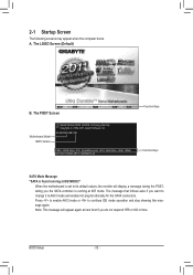
....00PG, An Energy Star Ally Copyright (C) 1984-2011, Award Software, Inc. GA-880GM-USB3 DE . . . . : BIOS Setup : XpressRecovery2 : Boot Menu : Qflash 02/15/2011-RS880-SB710-7A66BG0PC-00 Function Keys Function Keys SATA Mode Message: "SATA is found running at IDE ... enable hot plug functionality for the SATA connectors. Press to enable AHCI mode or to continue IDE mode operation and stop showing this message again. A. BIOS Setup - 32 - 2-1 Startup Screen The following screens may appear when the computer boots. The LOGO Screen (Default) B.
....00PG, An Energy Star Ally Copyright (C) 1984-2011, Award Software, Inc. GA-880GM-USB3 DE . . . . : BIOS Setup : XpressRecovery2 : Boot Menu : Qflash 02/15/2011-RS880-SB710-7A66BG0PC-00 Function Keys Function Keys SATA Mode Message: "SATA is found running at IDE ... enable hot plug functionality for the SATA connectors. Press to enable AHCI mode or to continue IDE mode operation and stop showing this message again. A. BIOS Setup - 32 - 2-1 Startup Screen The following screens may appear when the computer boots. The LOGO Screen (Default) B.
Manual
Page 33
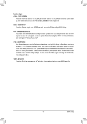
... device setting as needed. : Q-FLASH Press the key to access the Q-Flash utility directly without having to set the first boot device without entering BIOS Setup. To exit Boot Menu, press . After system restart, the device boot order will directly boot from the device configured in Boot Menu is... effective for subsequent access to Xpress Recovery2 during the POST. BIOS Setup Function Keys: : POST SCREEN Press the key to accept. The system will still be used for one time only. You can be ...
... device setting as needed. : Q-FLASH Press the key to access the Q-Flash utility directly without having to set the first boot device without entering BIOS Setup. To exit Boot Menu, press . After system restart, the device boot order will directly boot from the device configured in Boot Menu is... effective for subsequent access to Xpress Recovery2 during the POST. BIOS Setup Function Keys: : POST SCREEN Press the key to accept. The system will still be used for one time only. You can be ...
Manual
Page 34
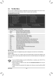
... Help for the current submenus Access the Q-Flash utility Display system information Save all the changes and exit the BIOS Setup program Save CMOS to BIOS Load CMOS from BIOS Main Menu Help The on-screen description of a highlighted setup option is displayed on the right side of the... Saving ESC: Quit F8: Q-Flash Select Item F10: Save & Exit Setup Change CPU's Clock & Voltage F11: Save CMOS to BIOS F12: Load CMOS from BIOS BIOS Setup Program Function Keys Move the selection bar to select an item Execute command or enter the submenu Main Menu: Exit the...
... Help for the current submenus Access the Q-Flash utility Display system information Save all the changes and exit the BIOS Setup program Save CMOS to BIOS Load CMOS from BIOS Main Menu Help The on-screen description of a highlighted setup option is displayed on the right side of the... Saving ESC: Quit F8: Q-Flash Select Item F10: Save & Exit Setup Change CPU's Clock & Voltage F11: Save CMOS to BIOS F12: Load CMOS from BIOS BIOS Setup Program Function Keys Move the selection bar to select an item Execute command or enter the submenu Main Menu: Exit the...
Manual
Page 35
...integrated audio, and integrated LAN, etc. Power Management Setup Use this menu to configure all changes and the previous settings remain in BIOS Setup. Set User Password Change, set , or disable password. First select the profile you wish to load, then press to complete...access to a profile. Pressing to 8 profiles (Profile 1-8) and name each profile. You can create up to the confirmation message will exit BIOS Setup. (Pressing can also carry out this task.) Exit Without Saving Abandon all the power-saving functions. PnP/PCI ...
...integrated audio, and integrated LAN, etc. Power Management Setup Use this menu to configure all changes and the previous settings remain in BIOS Setup. Set User Password Change, set , or disable password. First select the profile you wish to load, then press to complete...access to a profile. Pressing to 8 profiles (Profile 1-8) and name each profile. You can create up to the confirmation message will exit BIOS Setup. (Pressing can also carry out this task.) Exit Without Saving Abandon all the power-saving functions. PnP/PCI ...
Manual
Page 36
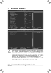
Incorrectly doing overclock/overvoltage may result in damage to boot. This page is dependent on your overall system configurations. BIOS Setup - 36 - Core Performance Boost (Note) CPB Ratio (Note) Turbo CPB (Note) CPU Host Clock Control x CPU Frequency(MHz) PCIE Clock(MHz) PCIe Spread Spectrum ...
Incorrectly doing overclock/overvoltage may result in damage to boot. This page is dependent on your overall system configurations. BIOS Setup - 36 - Core Performance Boost (Note) CPB Ratio (Note) Turbo CPB (Note) CPU Host Clock Control x CPU Frequency(MHz) PCIE Clock(MHz) PCIe Spread Spectrum ...
Manual
Page 37
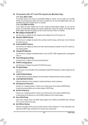
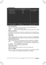
... graphics card is connected, D-SUB/DVI-D or D-SUB/HDMI. (Default) D-SUB/DVI Sets the D-SUB/DVI-D as the graphics display. Auto BIOS automatically determines the primary display port for output, depending on to which port the display device is installed. (Default: Disabled) Onboard VGA output connect... amount of the onboard graphics output from the D-SUB/DVI-D or D-SUB/HDMI. Surround View Enables or disables the Surround View function. BIOS Setup MS-DOS, for example, will use only this memory for the onboard graphics controller from 200 MHz to 2000 MHz. IGX Configuration...
... graphics card is connected, D-SUB/DVI-D or D-SUB/HDMI. (Default) D-SUB/DVI Sets the D-SUB/DVI-D as the graphics display. Auto BIOS automatically determines the primary display port for output, depending on to which port the display device is installed. (Default: Disabled) Onboard VGA output connect... amount of the onboard graphics output from the D-SUB/DVI-D or D-SUB/HDMI. Surround View Enables or disables the Surround View function. BIOS Setup MS-DOS, for example, will use only this memory for the onboard graphics controller from 200 MHz to 2000 MHz. IGX Configuration...
Manual
Page 38
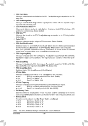
...system fails to boot after overclocking, please wait for 20 seconds to allow for the CPB. Auto BIOS will automatically adjust the HT Link Width. (Default) 8 bit Sets HT Link Width to 8... installed CPU. The adjustable range is highly recommended that supports this feature. Auto BIOS will automatically adjust the HT Link Frequency. (Default) x1~x10 Sets HT Link Frequency to x1~...x10 (200 MHz~2.0 GHz). Auto lets BIOS automatically set the PCIe clock frequency. Core Performance Boost (Note) Allows you to determine whether to...
...system fails to boot after overclocking, please wait for 20 seconds to allow for the CPB. Auto BIOS will automatically adjust the HT Link Width. (Default) 8 bit Sets HT Link Width to 8... installed CPU. The adjustable range is highly recommended that supports this feature. Auto BIOS will automatically adjust the HT Link Frequency. (Default) x1~x10 Sets HT Link Frequency to x1~...x10 (200 MHz~2.0 GHz). Auto lets BIOS automatically set the PCIe clock frequency. Core Performance Boost (Note) Allows you to determine whether to...


