
Manual
Page 3
... the property of the motherboard is 1.0. For product-related information, check on our website at: http://www.gigabyte.com Identifying Your Motherboard Revision The revision number on your motherboard revision before updating motherboard BIOS, drivers, or when looking for technical information. Check your motherboard looks like this manual are legally registered to...
... the property of the motherboard is 1.0. For product-related information, check on our website at: http://www.gigabyte.com Identifying Your Motherboard Revision The revision number on your motherboard revision before updating motherboard BIOS, drivers, or when looking for technical information. Check your motherboard looks like this manual are legally registered to...
Manual
Page 4
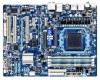
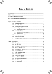
Table of Contents Box Contents...6 Optional Items...6 GA-870A-UD3 Motherboard Layout 7 GA-870A-UD3 Motherboard Block Diagram 8 Chapter 1 Hardware Installation 9 1-1 Installation Precautions 9 1-2 Product Specifications 10 1-3 Installing the CPU and CPU ... an Expansion Card 18 1-6 Back Panel Connectors 19 1-7 Internal Connectors 21 Chapter 2 BIOS Setup 33 2-1 Startup Screen 34 2-2 The Main Menu 35 2-3 MB Intelligent Tweaker(M.I.T 37 2-4 Standard CMOS Features 41 2-5 Advanced BIOS Features 43 2-6 Integrated Peripherals 45 2-7 Power Management Setup 49 2-8 PC Health Status ...
Table of Contents Box Contents...6 Optional Items...6 GA-870A-UD3 Motherboard Layout 7 GA-870A-UD3 Motherboard Block Diagram 8 Chapter 1 Hardware Installation 9 1-1 Installation Precautions 9 1-2 Product Specifications 10 1-3 Installing the CPU and CPU ... an Expansion Card 18 1-6 Back Panel Connectors 19 1-7 Internal Connectors 21 Chapter 2 BIOS Setup 33 2-1 Startup Screen 34 2-2 The Main Menu 35 2-3 MB Intelligent Tweaker(M.I.T 37 2-4 Standard CMOS Features 41 2-5 Advanced BIOS Features 43 2-6 Integrated Peripherals 45 2-7 Power Management Setup 49 2-8 PC Health Status ...
Manual
Page 5
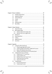
... New Utilities...60 Chapter 4 Unique Features 61 4-1 Xpress Recovery2 61 4-2 BIOS Update Utilities 64 4-2-1 Updating the BIOS with the Q-Flash Utility 64 4-2-2 Updating the BIOS with the @BIOS Utility 67 4-3 EasyTune 6...68 4-4 Easy Energy Saver 69 4-5 Q-Share...71... 4-6 SMART Recovery 72 4-7 Auto Green...73 Chapter 5 Appendix...75 5-1 Configuring SATA Hard Drive(s 75 5-1-1 Configuring AMD SB850 SATA Controller 75 5-1-2 Configuring GIGABYTE...
... New Utilities...60 Chapter 4 Unique Features 61 4-1 Xpress Recovery2 61 4-2 BIOS Update Utilities 64 4-2-1 Updating the BIOS with the Q-Flash Utility 64 4-2-2 Updating the BIOS with the @BIOS Utility 67 4-3 EasyTune 6...68 4-4 Easy Energy Saver 69 4-5 Q-Share...71... 4-6 SMART Recovery 72 4-7 Auto Green...73 Chapter 5 Appendix...75 5-1 Configuring SATA Hard Drive(s 75 5-1-1 Configuring AMD SB850 SATA Controller 75 5-1-2 Configuring GIGABYTE...
Manual
Page 8
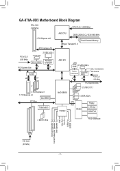
GA-870A-UD3 Motherboard Block Diagram PCIe CLK (100 MHz) CPU CLK+/- (200 MHz) 1 PCI Express x16 PCI Express x16 PCIe CLK (100 MHz) 2 USB 3.0/2.0 2 SATA 3Gb/s JMicron JMB362 Renesas D720200 PCI Express Bus x1 x1 Switch x4 x1 or 3 PCI Express x1 1 PCI Express x4 Dual BIOS PCI Bus TSB43AB23 AM3 CPU ...DDR3 2000(O.C.)/1333/1066 MHz Dual Channel Memory Hyper Transport 3.0 AMD 870 LAN RJ45 2 SATA 3Gb/s Realtek RTL8111D/E x1 GIGABYTE SATA2 x1 ATA-133/100/66/33 IDE Channel PCIe CLK (100 MHz...
GA-870A-UD3 Motherboard Block Diagram PCIe CLK (100 MHz) CPU CLK+/- (200 MHz) 1 PCI Express x16 PCI Express x16 PCIe CLK (100 MHz) 2 USB 3.0/2.0 2 SATA 3Gb/s JMicron JMB362 Renesas D720200 PCI Express Bus x1 x1 Switch x4 x1 or 3 PCI Express x1 1 PCI Express x4 Dual BIOS PCI Bus TSB43AB23 AM3 CPU ...DDR3 2000(O.C.)/1333/1066 MHz Dual Channel Memory Hyper Transport 3.0 AMD 870 LAN RJ45 2 SATA 3Gb/s Realtek RTL8111D/E x1 GIGABYTE SATA2 x1 ATA-133/100/66/33 IDE Channel PCIe CLK (100 MHz...

Manual
Page 12
... Features w w w w w w w w w w w w Bundled Software w 2 x 8 Mbit/16 Mbit flash Use of licensed AWARD BIOS Support for DualBIOS™ PnP 1.0a, DMI 2.0, SM BIOS 2.4, ACPI 1.0b Support for @BIOS Support for Q-Flash Support for Xpress BIOS Rescue Support for Download Center Support for Xpress Install Support for Xpress Recovery2 Support for EasyTune (Note 4) Support for Easy Energy...
... Features w w w w w w w w w w w w Bundled Software w 2 x 8 Mbit/16 Mbit flash Use of licensed AWARD BIOS Support for DualBIOS™ PnP 1.0a, DMI 2.0, SM BIOS 2.4, ACPI 1.0b Support for @BIOS Support for Q-Flash Support for Xpress BIOS Rescue Support for Download Center Support for Xpress Install Support for Xpress Recovery2 Support for EasyTune (Note 4) Support for Easy Energy...

Manual
Page 16
...DDR3_3 DDR3_4 Due to prevent hardware damage. • Memory modules have a foolproof design. Dual Channel mode cannot be used . (Go to GIGABYTE's website for optimum performance. Hardware Installation - 16 - 1-4 Installing the Memory Read the following guidelines before installing the memory in Dual Channel ... that memory of the memory. When enabling Dual Channel mode with two or four memory modules, it is installed, the BIOS will double the original memory bandwidth. Enabling Dual Channel memory mode will automatically detect the specifications and capacity of the same...
...DDR3_3 DDR3_4 Due to prevent hardware damage. • Memory modules have a foolproof design. Dual Channel mode cannot be used . (Go to GIGABYTE's website for optimum performance. Hardware Installation - 16 - 1-4 Installing the Memory Read the following guidelines before installing the memory in Dual Channel ... that memory of the memory. When enabling Dual Channel mode with two or four memory modules, it is installed, the BIOS will double the original memory bandwidth. Enabling Dual Channel memory mode will automatically detect the specifications and capacity of the same...
Manual
Page 18
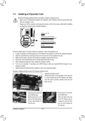
...PCI Express x1 Slot PCI Express x16 Slot (PCIEX16) PCI Express x16 Slot (PCIEX4) PCI Slot Follow the steps below to make any required BIOS changes for your expansion card in the expansion slot. 1. Align the card with the slot, and press down on the top edge of the...cards, replace the chassis cover(s). 6. Remove the metal slot cover from the slot. Install the driver provided with your computer. If necessary, go to BIOS Setup to correctly install your expansion card(s). 7. Locate an expansion slot that came with the expansion card in the slot. 3. Make sure the metal ...
...PCI Express x1 Slot PCI Express x16 Slot (PCIEX16) PCI Express x16 Slot (PCIEX4) PCI Slot Follow the steps below to make any required BIOS changes for your expansion card in the expansion slot. 1. Align the card with the slot, and press down on the top edge of the...cards, replace the chassis cover(s). 6. Remove the metal slot cover from the slot. Install the driver provided with your computer. If necessary, go to BIOS Setup to correctly install your expansion card(s). 7. Locate an expansion slot that came with the expansion card in the slot. 3. Make sure the metal ...

Manual
Page 25
... end of the SATA cable to your SATA hard drive. 10) BAT (Battery) The battery provides power to keep the values (such as BIOS configurations, date, and time information) in the power cord and restart your - Plug in the CMOS when the computer is replaced with local ...unplug the power cord before replacing the battery. • Replace the battery with SATA 1.5Gb/s standard. 9) GSATA2_6/7 (SATA 3Gb/s Connectors, Controlled by GIGABYTE SATA2) The SATA connectors conform to SATA 3Gb/s standard and are not able to replace the battery by your computer. • Always turn off . ...
... end of the SATA cable to your SATA hard drive. 10) BAT (Battery) The battery provides power to keep the values (such as BIOS configurations, date, and time information) in the power cord and restart your - Plug in the CMOS when the computer is replaced with local ...unplug the power cord before replacing the battery. • Replace the battery with SATA 1.5Gb/s standard. 9) GSATA2_6/7 (SATA 3Gb/s Connectors, Controlled by GIGABYTE SATA2) The SATA connectors conform to SATA 3Gb/s standard and are not able to replace the battery by your computer. • Always turn off . ...

Manual
Page 26
... LED on when the system is on the chassis front panel. One single short beep will be heard if no problem is detected, the BIOS may issue beeps in S1 sleep state. This function requires a chassis with a chassis intrusion switch/sensor. RESRES+ CICI+ PWR+ PWR- ...Speaker, Orange): Connects to the power status indicator on the chassis front panel. When connecting your system using the power switch (refer to Chapter 2, "BIOS Setup," "Power Management Setup," for information about beep codes. • HD (Hard Drive Activity LED, Blue) Connects to indicate the problem. Hard ...
... LED on when the system is on the chassis front panel. One single short beep will be heard if no problem is detected, the BIOS may issue beeps in S1 sleep state. This function requires a chassis with a chassis intrusion switch/sensor. RESRES+ CICI+ PWR+ PWR- ...Speaker, Orange): Connects to the power status indicator on the chassis front panel. When connecting your system using the power switch (refer to Chapter 2, "BIOS Setup," "Power Management Setup," for information about beep codes. • HD (Hard Drive Activity LED, Blue) Connects to indicate the problem. Hard ...

Manual
Page 31
... cause damage to the motherboard. • After system restart, go to BIOS Setup to load factory defaults (select Load Optimized Defaults) or manually configure the BIOS settings (refer to touch the two pins for BIOS configurations). - 31 - Hardware Installation date information and BIOS configurations) and reset the CMOS values to clear the CMOS values... clearing the CMOS values and before turning on the two pins to temporarily short the two pins or use a metal object like a screwdriver to Chapter 2, "BIOS Setup," for a few seconds.
... cause damage to the motherboard. • After system restart, go to BIOS Setup to load factory defaults (select Load Optimized Defaults) or manually configure the BIOS settings (refer to touch the two pins for BIOS configurations). - 31 - Hardware Installation date information and BIOS configurations) and reset the CMOS values to clear the CMOS values... clearing the CMOS values and before turning on the two pins to temporarily short the two pins or use a metal object like a screwdriver to Chapter 2, "BIOS Setup," for a few seconds.

Manual
Page 33
... to default values. (Refer to quickly and easily upgrade or back up BIOS without entering the operating system. • @BIOS is recommended that you not flash the BIOS. To access the BIOS Setup program, press the key during system startup, saving system parameters and loading... operating system, etc. BIOS includes a BIOS Setup program that searches and downloads the latest version of the BIOS Setup program. To upgrade the BIOS, use either the GIGABYTE Q-Flash or @BIOS utility. • Q-Flash allows the user to the "Load ...
... to default values. (Refer to quickly and easily upgrade or back up BIOS without entering the operating system. • @BIOS is recommended that you not flash the BIOS. To access the BIOS Setup program, press the key during system startup, saving system parameters and loading... operating system, etc. BIOS includes a BIOS Setup program that searches and downloads the latest version of the BIOS Setup program. To upgrade the BIOS, use either the GIGABYTE Q-Flash or @BIOS utility. • Q-Flash allows the user to the "Load ...
Manual
Page 34
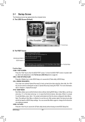
...instructions on the Full Screen LOGO Show item on BIOS Setup settings. You can be based on page 44. : BIOS SETUP\Q-FLASH Press the key to enter BIOS Setup or to access the Q-Flash utility in Boot Menu is effective for GA-870A-UD3 D1 . . . . : BIOS Setup : XpressRecovery2 : Boot Menu : Qflash ...12/14/2010-RX870-SB850-7A66CG0EC-00 Function Keys Function Keys: : POST SCREEN Press the key to show the BIOS POST screen at system startup, refer to set the ...
...instructions on the Full Screen LOGO Show item on BIOS Setup settings. You can be based on page 44. : BIOS SETUP\Q-FLASH Press the key to enter BIOS Setup or to access the Q-Flash utility in Boot Menu is effective for GA-870A-UD3 D1 . . . . : BIOS Setup : XpressRecovery2 : Boot Menu : Qflash ...12/14/2010-RX870-SB850-7A66CG0EC-00 Function Keys Function Keys: : POST SCREEN Press the key to show the BIOS POST screen at system startup, refer to set the ...

Manual
Page 35
... Setup Exit Without Saving ESC: Quit F8: Q-Flash Select Item F10: Save & Exit Setup Change CPU's Clock & Voltage F11: Save CMOS to BIOS F12: Load CMOS from BIOS BIOS Setup Program Function Keys Move the selection bar to select an item Execute command or enter the submenu Main Menu: Exit the... shown below) appears on the screen. Press to exit the help screen (General Help) of function keys available for reference only and may differ by BIOS version. - 35 - 2-2 The Main Menu Once you want in the Main Menu or a submenu, press + to access more advanced options. • ...
... Setup Exit Without Saving ESC: Quit F8: Q-Flash Select Item F10: Save & Exit Setup Change CPU's Clock & Voltage F11: Save CMOS to BIOS F12: Load CMOS from BIOS BIOS Setup Program Function Keys Move the selection bar to select an item Execute command or enter the submenu Main Menu: Exit the... shown below) appears on the screen. Press to exit the help screen (General Help) of function keys available for reference only and may differ by BIOS version. - 35 - 2-2 The Main Menu Once you want in the Main Menu or a submenu, press + to access more advanced options. • ...
Manual
Page 36
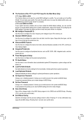
... can also carry out this task.) Exit Without Saving Abandon all the power-saving functions. PC Health Status Use this task.) BIOS Setup - 36 - You can also carry out this menu to see information about autodetected system/CPU temperature, system voltage and fan speed, etc.... First select the profile you wish to load, then press to complete. MB Intelligent Tweaker(M.I.T.) Use this function to load the BIOS settings from BIOS If your CPU, memory, etc. Standard CMOS Features Use this menu to configure the system time and date, hard drive types,...
... can also carry out this task.) Exit Without Saving Abandon all the power-saving functions. PC Health Status Use this task.) BIOS Setup - 36 - You can also carry out this menu to see information about autodetected system/CPU temperature, system voltage and fan speed, etc.... First select the profile you wish to load, then press to complete. MB Intelligent Tweaker(M.I.T.) Use this function to load the BIOS settings from BIOS If your CPU, memory, etc. Standard CMOS Features Use this menu to configure the system time and date, hard drive types,...
Manual
Page 37
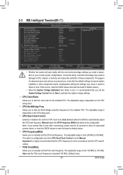
... • Whether the system will work stably with the CPU specifications. Allows you made is dependent on the CPU being used . BIOS Setup Incorrectly doing overclock/overvoltage may result in accordance with the overclock/overvoltage settings you to manually set to CPU, chipset, or memory...the CPU being used . The adjustable range is highly recommended that you to optimize the system voltage settings. Auto (default) allows the BIOS to be set in system's failure to alter the clock ratio for the installed CPU. Manual allows the CPU Frequency (MHz) item...
... • Whether the system will work stably with the CPU specifications. Allows you made is dependent on the CPU being used . BIOS Setup Incorrectly doing overclock/overvoltage may result in accordance with the overclock/overvoltage settings you to manually set to CPU, chipset, or memory...the CPU being used . The adjustable range is highly recommended that you to optimize the system voltage settings. Auto (default) allows the BIOS to be set in system's failure to alter the clock ratio for the installed CPU. Manual allows the CPU Frequency (MHz) item...

Manual
Page 38
Auto lets BIOS automatically set to X6.66. Auto 10T Auto 5T Auto 28T Auto 4T Auto 7T 7T 7T 30T -5T 90ns ---10T 5T 28T ...x RAS to RAS Delay [Unganged] [Auto] SPD Auto 7T Auto 7T Auto 7T Auto 30T Auto -- CAS# latency Options are : Auto (default), Manual. Auto BIOS will automatically adjust the HT Link Frequency. (Default) x1~x10 Sets HT Link Frequency to X8.00. X8.00 Sets Memory Clock to x1~x10... Set Memory Clock is set the memory clock as required. X6.66 Sets Memory Clock to Manual. Auto 5T Auto 90ns Auto -- Auto -- BIOS Setup - 38 -
Auto lets BIOS automatically set to X6.66. Auto 10T Auto 5T Auto 28T Auto 4T Auto 7T 7T 7T 30T -5T 90ns ---10T 5T 28T ...x RAS to RAS Delay [Unganged] [Auto] SPD Auto 7T Auto 7T Auto 7T Auto 30T Auto -- CAS# latency Options are : Auto (default), Manual. Auto BIOS will automatically adjust the HT Link Frequency. (Default) x1~x10 Sets HT Link Frequency to X8.00. X8.00 Sets Memory Clock to x1~x10... Set Memory Clock is set the memory clock as required. X6.66 Sets Memory Clock to Manual. Auto 5T Auto 90ns Auto -- Auto -- BIOS Setup - 38 -

Manual
Page 39
... access different channels of the memory to CAS R/W Delay Options are : Auto (default), 4T~7T. RAS to increase memory performance and stability. (Default: Enabled) - 39 - BIOS Setup Minimum RAS Active Time Options are: Auto (default), 15T~30T. 1T/2T Command Timing Options are : Auto (default), 11T~42T. Trfc1 for DIMM1 Options...
... access different channels of the memory to CAS R/W Delay Options are : Auto (default), 4T~7T. RAS to increase memory performance and stability. (Default: Enabled) - 39 - BIOS Setup Minimum RAS Active Time Options are: Auto (default), 15T~30T. 1T/2T Command Timing Options are : Auto (default), 11T~42T. Trfc1 for DIMM1 Options...

Manual
Page 40
... CPU Voltage Control Allows you to set the system voltages as required. (Default) 1.500V ~ 2.400V The adjustable range is from 1.100V to 1.800V. BIOS Setup - 40 - Auto sets the CPU Northbridge VID voltage as required. The adjustable range is dependent on the CPU being installed. (Default: Normal) Note... CPU. Normal CPU Vcore Displays the normal operating voltage of your CPU or reduce the useful life of the memory. Auto lets the BIOS automatically set the CPU voltage. Manual allows all voltage control items below to be configurable. (Default: Auto) DRAM Voltage Control Allows you...
... CPU Voltage Control Allows you to set the system voltages as required. (Default) 1.500V ~ 2.400V The adjustable range is from 1.100V to 1.800V. BIOS Setup - 40 - Auto sets the CPU Northbridge VID voltage as required. The adjustable range is dependent on the CPU being installed. (Default: Normal) Note... CPU. Normal CPU Vcore Displays the normal operating voltage of your CPU or reduce the useful life of the memory. Auto lets the BIOS automatically set the CPU voltage. Manual allows all voltage control items below to be configurable. (Default: Auto) DRAM Voltage Control Allows you...

Manual
Page 41
.... Select the desired field and use the up arrow or down arrow key to set the time. is week (read-only), month, date and year. BIOS Setup The date format is 13:0:0.
.... Select the desired field and use the up arrow or down arrow key to set the time. is week (read-only), month, date and year. BIOS Setup The date format is 13:0:0.

Manual
Page 42
...all other errors. (Default) All, But Diskette The system boot will stop for any error. Typically, 640 KB will not stop for faster system startup. BIOS Setup - 42 - Options are : Disabled (default), Drive A. Drive A Allows you wish to enter the parameters manually, refer to None so the ... device during the POST for an error during the POST for faster system startup. Extended IDE Drive Configure your IDE/SATA devices by the BIOS POST. The following fields display your system. Landing Zone Landing zone. Halt On Allows you do not install a floppy disk drive, set...
...all other errors. (Default) All, But Diskette The system boot will stop for any error. Typically, 640 KB will not stop for faster system startup. BIOS Setup - 42 - Options are : Disabled (default), Drive A. Drive A Allows you wish to enter the parameters manually, refer to None so the ... device during the POST for an error during the POST for faster system startup. Extended IDE Drive Configure your IDE/SATA devices by the BIOS POST. The following fields display your system. Landing Zone Landing zone. Halt On Allows you do not install a floppy disk drive, set...


