Manual
Page 3
... on your motherboard revision before updating motherboard BIOS, drivers, or when looking for technical information. Documentation Classifications In order to use of GIGABYTE. Copyright © 2009 GIGA-BYTE TECHNOLOGY CO., LTD. Disclaimer Information in the use GIGABYTE's unique features, read the User's Manual... the specifications and features in this : "REV: X.X." For product-related information, check on our website at: http://www.gigabyte.com.tw Identifying Your Motherboard Revision The revision number on how to assist in this manual may be made by copyright laws...
... on your motherboard revision before updating motherboard BIOS, drivers, or when looking for technical information. Documentation Classifications In order to use of GIGABYTE. Copyright © 2009 GIGA-BYTE TECHNOLOGY CO., LTD. Disclaimer Information in the use GIGABYTE's unique features, read the User's Manual... the specifications and features in this : "REV: X.X." For product-related information, check on our website at: http://www.gigabyte.com.tw Identifying Your Motherboard Revision The revision number on how to assist in this manual may be made by copyright laws...
Manual
Page 4
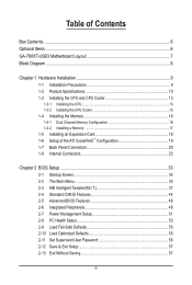
Table of Contents Box Contents...6 Optional Items...6 GA-790XT-USB3 Motherboard Layout 7 Block Diagram...8 Chapter 1 Hardware Installation 9 1-1 Installation Precautions 9 1-2 Product Specifications 10 1-3 Installing the CPU and CPU Cooler 13...ATI CrossFireX™ Configuration 19 1-7 Back Panel Connectors 20 1-8 Internal Connectors 22 Chapter 2 BIOS Setup 33 2-1 Startup Screen 34 2-2 The Main Menu 35 2-3 MB Intelligent Tweaker(M.I.T 37 2-4 Standard CMOS Features 44 2-5 Advanced BIOS Features 46 2-6 Integrated Peripherals 48 2-7 Power Management Setup 51 2-8 PC Health Status 53...
Table of Contents Box Contents...6 Optional Items...6 GA-790XT-USB3 Motherboard Layout 7 Block Diagram...8 Chapter 1 Hardware Installation 9 1-1 Installation Precautions 9 1-2 Product Specifications 10 1-3 Installing the CPU and CPU Cooler 13...ATI CrossFireX™ Configuration 19 1-7 Back Panel Connectors 20 1-8 Internal Connectors 22 Chapter 2 BIOS Setup 33 2-1 Startup Screen 34 2-2 The Main Menu 35 2-3 MB Intelligent Tweaker(M.I.T 37 2-4 Standard CMOS Features 44 2-5 Advanced BIOS Features 46 2-6 Integrated Peripherals 48 2-7 Power Management Setup 51 2-8 PC Health Status 53...

Manual
Page 5
... 60 3-3 Technical Manuals 60 3-4 Contact...61 3-5 System...61 3-6 Download Center 62 Chapter 4 Unique Features 63 4-1 Xpress Recovery2 63 4-2 BIOS Update Utilities 66 4-2-1 Updating the BIOS with the Q-Flash Utility 66 4-2-2 Updating the BIOS with the @BIOS Utility 69 4-3 EasyTune 6...70 4-4 Easy Energy Saver 71 4-5 Q-Share...73 4-6 Time Repair...74 Chapter 5 Appendix...75 5-1 Configuring SATA...
... 60 3-3 Technical Manuals 60 3-4 Contact...61 3-5 System...61 3-6 Download Center 62 Chapter 4 Unique Features 63 4-1 Xpress Recovery2 63 4-2 BIOS Update Utilities 66 4-2-1 Updating the BIOS with the Q-Flash Utility 66 4-2-2 Updating the BIOS with the @BIOS Utility 69 4-3 EasyTune 6...70 4-4 Easy Energy Saver 71 4-5 Q-Share...73 4-6 Time Repair...74 Chapter 5 Appendix...75 5-1 Configuring SATA...
Manual
Page 8
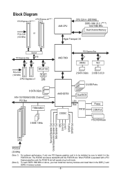
... IDE Channel PCI Bus TSB43AB23 3 IEEE 1394a AMD 790X PCI Express Bus x1 x1 JMB362 NEC 2 SATA 3Gb/s 2 USB 3.0/2.0 12 USB Ports AMD SB750 Dual BIOS CODEC LPC Bus IT8720 Floppy COM Port PS/2 KB/Mouse Surround Speaker Out Center/Subwoofer Speaker Out Side Speaker Out MIC Line Out Line In...
... IDE Channel PCI Bus TSB43AB23 3 IEEE 1394a AMD 790X PCI Express Bus x1 x1 JMB362 NEC 2 SATA 3Gb/s 2 USB 3.0/2.0 12 USB Ports AMD SB750 Dual BIOS CODEC LPC Bus IT8720 Floppy COM Port PS/2 KB/Mouse Surround Speaker Out Center/Subwoofer Speaker Out Side Speaker Out MIC Line Out Line In...

Manual
Page 12
.../Power fan fail warning CPU/System fan speed control (Note 4) 2 x 8 Mbit flash Use of licensed AWARD BIOS Support for DualBIOS™ PnP 1.0a, DMI 2.0, SM BIOS 2.4, ACPI 1.0b Support for @BIOS Support for Q-Flash Support for Xpress BIOS Rescue Support for Download Center Support for Xpress Install Support for Xpress Recovery2 Support for EasyTune...
.../Power fan fail warning CPU/System fan speed control (Note 4) 2 x 8 Mbit flash Use of licensed AWARD BIOS Support for DualBIOS™ PnP 1.0a, DMI 2.0, SM BIOS 2.4, ACPI 1.0b Support for @BIOS Support for Q-Flash Support for Xpress BIOS Rescue Support for Download Center Support for Xpress Install Support for Xpress Recovery2 Support for EasyTune...

Manual
Page 16
... cannot be enabled if only one direction. A memory module can be installed in only one DDR3 memory module is installed, the BIOS will double the original memory bandwidth. When enabling Dual Channel mode with two or four memory modules, it is recommended that the ...memory. Hardware Installation - 16 - It is recommended that memory of the same capacity, brand, speed, and chips be used . (Go to GIGABYTE's website for optimum performance. The four DDR3 memory sockets are unable to insert the memory, switch the direction. 1-4-1 Dual Channel Memory Configuration This ...
... cannot be enabled if only one direction. A memory module can be installed in only one DDR3 memory module is installed, the BIOS will double the original memory bandwidth. When enabling Dual Channel mode with two or four memory modules, it is recommended that the ...memory. Hardware Installation - 16 - It is recommended that memory of the same capacity, brand, speed, and chips be used . (Go to GIGABYTE's website for optimum performance. The four DDR3 memory sockets are unable to insert the memory, switch the direction. 1-4-1 Dual Channel Memory Configuration This ...
Manual
Page 18
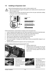
... Make sure the motherboard supports the expansion card. Turn on the card are completely inserted into the PCI Express slot. If necessary, go to BIOS Setup to correctly install your expansion card(s). 7. Make sure the card is fully inserted into the slot. 4. Example: Installing and Removing a ...PCI Express x1 Slot PCI Express x16 Slot (PCIEX16) PCI Express x16 Slot (PCIEX8) PCI Slot Follow the steps below to make any required BIOS changes for your expansion card in the slot. 3. Align the card with your card. Carefully read the manual that supports your expansion card. ...
... Make sure the motherboard supports the expansion card. Turn on the card are completely inserted into the PCI Express slot. If necessary, go to BIOS Setup to correctly install your expansion card(s). 7. Make sure the card is fully inserted into the slot. 4. Example: Installing and Removing a ...PCI Express x1 Slot PCI Express x16 Slot (PCIEX16) PCI Express x16 Slot (PCIEX8) PCI Slot Follow the steps below to make any required BIOS changes for your expansion card in the slot. 3. Align the card with your card. Carefully read the manual that supports your expansion card. ...

Manual
Page 26
... is on when the system is in S1 sleep state. S1 Blinking tem is operating. The LED is off when the system is detected, the BIOS may issue beeps in S3/S4 sleep S3/S4/S5 Off state or powered off your chassis front panel module to the pin assignments below... to turn off (S5). • PW (Power Switch, Red): Connects to indicate the problem. When connecting your system using the power switch (refer to Chapter 2, "BIOS Setup," "Power Management Setup," for information about beep codes. • HD (Hard Drive Activity LED, Blue) Connects to the chassis intrusion switch/sensor on the...
... is on when the system is in S1 sleep state. S1 Blinking tem is operating. The LED is off when the system is detected, the BIOS may issue beeps in S3/S4 sleep S3/S4/S5 Off state or powered off your chassis front panel module to the pin assignments below... to turn off (S5). • PW (Power Switch, Red): Connects to indicate the problem. When connecting your system using the power switch (refer to Chapter 2, "BIOS Setup," "Power Management Setup," for information about beep codes. • HD (Hard Drive Activity LED, Blue) Connects to the chassis intrusion switch/sensor on the...
Manual
Page 30
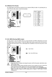
...5 GND 6 NDSR- 7 NRTS- 8 NCTS- 9 NRI- 10 No Pin 17) CLR_CMOS (Clearing CMOS Jumper) Use this jumper to touch the two pins for BIOS configurations). Hardware Installation - 30 - To clear the CMOS values, place a jumper cap on your computer and unplug the power cord from the jumper. Open: Normal... to clear the CMOS values (e.g. For purchasing the optional COM port cable, please contact the local dealer. Pin No. date information and BIOS configurations) and reset the CMOS values to factory defaults. 16) COM (Serial Port Header) The COM header can provide one serial port...
...5 GND 6 NDSR- 7 NRTS- 8 NCTS- 9 NRI- 10 No Pin 17) CLR_CMOS (Clearing CMOS Jumper) Use this jumper to touch the two pins for BIOS configurations). Hardware Installation - 30 - To clear the CMOS values, place a jumper cap on your computer and unplug the power cord from the jumper. Open: Normal... to clear the CMOS values (e.g. For purchasing the optional COM port cable, please contact the local dealer. Pin No. date information and BIOS configurations) and reset the CMOS values to factory defaults. 16) COM (Serial Port Header) The COM header can provide one serial port...

Manual
Page 31
You may be handled in accordance with an equivalent one minute. (Or use a metal object like a screwdriver to keep the values (such as BIOS configurations, date, and time information) in the power cord and restart your computer. • Always turn off your computer and unplug the power cord before ...
You may be handled in accordance with an equivalent one minute. (Or use a metal object like a screwdriver to keep the values (such as BIOS configurations, date, and time information) in the power cord and restart your computer. • Always turn off your computer and unplug the power cord before ...

Manual
Page 33
... and easily upgrade or back up BIOS without entering the operating system. • @BIOS is turned on using the current version of BIOS, it is potentially risky, if you not flash the BIOS. Refer to Chapter 5, "Troubleshooting," for how to boot. To upgrade the BIOS, use either the GIGABYTE Q-Flash or @BIOS utility. • Q-Flash allows the...
... and easily upgrade or back up BIOS without entering the operating system. • @BIOS is turned on using the current version of BIOS, it is potentially risky, if you not flash the BIOS. Refer to Chapter 5, "Troubleshooting," for how to boot. To upgrade the BIOS, use either the GIGABYTE Q-Flash or @BIOS utility. • Q-Flash allows the...
Manual
Page 34
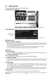
...BIOS Version GA-790XT-USB3 F1a . . . . : BIOS Setup : XpressRecovery2 : Boot Menu : Qflash 12/8/2009-RD780-SB750-7A66AG0ZC-00 Function Keys SATA Mode Message: "SATA is running at system startup, refer to the instructions on the Full Screen LOGO Show item on BIOS Setup settings. Press to enable AHCI mode or to enter BIOS... restart, the device boot order will directly boot from the device configured in BIOS Setup. : XPRESS RECOVERY2 If you to set to accept. To show the BIOS POST screen. BIOS Setup - 34 - When the motherboard is effective for the SATA connectors....
...BIOS Version GA-790XT-USB3 F1a . . . . : BIOS Setup : XpressRecovery2 : Boot Menu : Qflash 12/8/2009-RD780-SB750-7A66AG0ZC-00 Function Keys SATA Mode Message: "SATA is running at system startup, refer to the instructions on the Full Screen LOGO Show item on BIOS Setup settings. Press to enable AHCI mode or to enter BIOS... restart, the device boot order will directly boot from the device configured in BIOS Setup. : XPRESS RECOVERY2 If you to set to accept. To show the BIOS POST screen. BIOS Setup - 34 - When the motherboard is effective for the SATA connectors....
Manual
Page 35
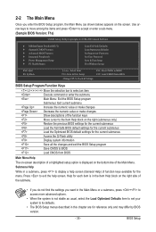
... Without Saving ESC: Quit F8: Q-Flash Select Item F10: Save & Exit Setup Change CPU's Clock & Voltage F11: Save CMOS to BIOS F12: Load CMOS from BIOS BIOS Setup Program Function Keys Move the selection bar to select an item Execute command or enter the submenu Main Menu: Exit the...settings for the current submenus Access the Q-Flash utility Display system information Save all the changes and exit the BIOS Setup program Save CMOS to BIOS Load CMOS from BIOS Main Menu Help The on-screen description of a highlighted setup option is displayed on the bottom line of...
... Without Saving ESC: Quit F8: Q-Flash Select Item F10: Save & Exit Setup Change CPU's Clock & Voltage F11: Save CMOS to BIOS F12: Load CMOS from BIOS BIOS Setup Program Function Keys Move the selection bar to select an item Execute command or enter the submenu Main Menu: Exit the...settings for the current submenus Access the Q-Flash utility Display system information Save all the changes and exit the BIOS Setup program Save CMOS to BIOS Load CMOS from BIOS Main Menu Help The on-screen description of a highlighted setup option is displayed on the bottom line of...
Manual
Page 36
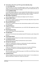
... types, floppy disk drive types, and the type of the and keys (For the Main Menu Only) F11: Save CMOS to BIOS This function allows you to restrict access to see information about autodetected system/CPU temperature, system voltage and fan speed, etc. Load Fail...factory settings for optimal-performance system operations. Set Supervisor Password Change, set , or disable password. It allows you to save the current BIOS settings to a profile. First select the profile you wish to load, then press to complete. MB Intelligent Tweaker(M.I.T.) Use this menu to...
... types, floppy disk drive types, and the type of the and keys (For the Main Menu Only) F11: Save CMOS to BIOS This function allows you to restrict access to see information about autodetected system/CPU temperature, system voltage and fan speed, etc. Load Fail...factory settings for optimal-performance system operations. Set Supervisor Password Change, set , or disable password. It allows you to save the current BIOS settings to a profile. First select the profile you wish to load, then press to complete. MB Intelligent Tweaker(M.I.T.) Use this menu to...
Manual
Page 37
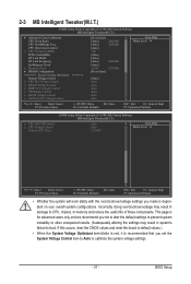
...: General Help F7: Optimized Defaults CMOS Setup Utility-Copyright (C) 1984-2009 Award Software MB Intelligent Tweaker(M.I .T.) } Advanced Clock Calibration CPU Clock Ratio CPU NorthBridge Freq. BIOS Setup Incorrectly doing overclock/overvoltage may result in damage to optimize the system voltage settings. - 37 -
...: General Help F7: Optimized Defaults CMOS Setup Utility-Copyright (C) 1984-2009 Award Software MB Intelligent Tweaker(M.I .T.) } Advanced Clock Calibration CPU Clock Ratio CPU NorthBridge Freq. BIOS Setup Incorrectly doing overclock/overvoltage may result in damage to optimize the system voltage settings. - 37 -

Manual
Page 38
... for a few seconds and the system will appear. Options are : Auto (default), Manual. Options are : -12%~+12%. Auto Lets the BIOS to enable all CPU cores. Advanced Clock Calibration Allows you to individually enable/disable CPU Core 2 and Core 3. Per Core Individually configures Advanced Clock...is set to All Cores. Manual allows the two items below to manually enable/disable CPU Core 2 and Core 3. BIOS Setup - 38 - After the selection, select Save & Exit Setup in the BIOS Main Menu and then press . CPU core 2 (Note) Enables or disables CPU Core 2. (Default: Enabled) ...
... for a few seconds and the system will appear. Options are : Auto (default), Manual. Options are : -12%~+12%. Auto Lets the BIOS to enable all CPU cores. Advanced Clock Calibration Allows you to individually enable/disable CPU Core 2 and Core 3. Per Core Individually configures Advanced Clock...is set to All Cores. Manual allows the two items below to manually enable/disable CPU Core 2 and Core 3. BIOS Setup - 38 - After the selection, select Save & Exit Setup in the BIOS Main Menu and then press . CPU core 2 (Note) Enables or disables CPU Core 2. (Default: Enabled) ...

Manual
Page 39
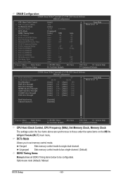
... the PCIe clock frequency. PCIE Clock(MHz) Allows you to alter the clock ratio for the HT Link between the CPU and chipset. Auto BIOS will automatically adjust the HT Link Frequency. (Default) x1~x10 Sets HT Link Frequency to be set the memory clock. Manual allows the memory... clock control item below to x1~x10 (200 MHz~2.0 GHz). BIOS Setup HT Link Frequency Allows you to X6.66. The adjustable range is highly recommended that supports this feature. - 39 - Set Memory Clock ...
... the PCIe clock frequency. PCIE Clock(MHz) Allows you to alter the clock ratio for the HT Link between the CPU and chipset. Auto BIOS will automatically adjust the HT Link Frequency. (Default) x1~x10 Sets HT Link Frequency to be set the memory clock. Manual allows the memory... clock control item below to x1~x10 (200 MHz~2.0 GHz). BIOS Setup HT Link Frequency Allows you to X6.66. The adjustable range is highly recommended that supports this feature. - 39 - Set Memory Clock ...
Manual
Page 40
... control mode. Ganged Sets memory control mode to be configurable. DCTs Mode Allows you to those under the four items above are : Auto (default), Manual. BIOS Setup - 40 -
... control mode. Ganged Sets memory control mode to be configurable. DCTs Mode Allows you to those under the four items above are : Auto (default), Manual. BIOS Setup - 40 -

Manual
Page 41
... (default), 1T, 2T. Minimum RAS Active Time Options are: Auto (default), 15T~30T. 1T/2T Command Timing Options are : Auto (default), 5T~8T, 10T, 12T. BIOS Setup RAS to RAS Delay Options are: Auto (default), 4T~7T. **DCTs Drive Strength** ProcOdt(ohms) Options are: Auto (default), 240 ohms, 120 ohms, 60...
... (default), 1T, 2T. Minimum RAS Active Time Options are: Auto (default), 15T~30T. 1T/2T Command Timing Options are : Auto (default), 5T~8T, 10T, 12T. BIOS Setup RAS to RAS Delay Options are: Auto (default), 4T~7T. **DCTs Drive Strength** ProcOdt(ohms) Options are: Auto (default), 240 ohms, 120 ohms, 60...

Manual
Page 42
...400V. Normal Supplies the North Bridge voltage as required. CS/ODT drive Strength Options are : Auto (default), 1.0x, 1.25x, 1.5x, 2.0x. BIOS Setup - 42 - Enabled allows the system to simultaneously access different banks of the memory to your CPU or reduce the useful life of the memory.... Auto lets the BIOS automatically set the memory VTT voltage. Note: Increasing CPU voltage may result in damage to increase memory performance and stability. (Default: Enabled)...
...400V. Normal Supplies the North Bridge voltage as required. CS/ODT drive Strength Options are : Auto (default), 1.0x, 1.25x, 1.5x, 2.0x. BIOS Setup - 42 - Enabled allows the system to simultaneously access different banks of the memory to your CPU or reduce the useful life of the memory.... Auto lets the BIOS automatically set the memory VTT voltage. Note: Increasing CPU voltage may result in damage to increase memory performance and stability. (Default: Enabled)...


