Manual
Page 3
... is 1.0. Example: For instructions on how to assist in this : "REV: X.X." No part of the product, read the User's Manual. All rights reserved. The trademarks mentioned in this manual are legally registered to the specifications and features in the use GIGABYTE's unique features, read or download the information on/from the Support&Downloads\Motherboard\Technology Guide page on your motherboard revision before updating motherboard BIOS, drivers, or when looking...
... is 1.0. Example: For instructions on how to assist in this : "REV: X.X." No part of the product, read the User's Manual. All rights reserved. The trademarks mentioned in this manual are legally registered to the specifications and features in the use GIGABYTE's unique features, read or download the information on/from the Support&Downloads\Motherboard\Technology Guide page on your motherboard revision before updating motherboard BIOS, drivers, or when looking...
Manual
Page 4
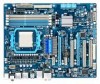
... Optional Items...6 GA-790XT-USB3 Motherboard Layout 7 Block Diagram...8 Chapter 1 Hardware Installation 9 1-1 Installation Precautions 9 1-2 Product Specifications 10 1-3 Installing the CPU and CPU Cooler 13 1-3-1 Installing the CPU 13 1-3-2 Installing the CPU Cooler 15 1-4 Installing the Memory 16 1-4-1 Dual Channel Memory Configuration 16 1-4-2 Installing a Memory 17 1-5 Installing an Expansion Card 18 1-6 Setup of the ATI CrossFireX™ Configuration 19 1-7 Back Panel Connectors 20 1-8 Internal Connectors 22 Chapter 2 BIOS Setup 33 2-1 Startup Screen 34 2-2 The Main Menu...
... Optional Items...6 GA-790XT-USB3 Motherboard Layout 7 Block Diagram...8 Chapter 1 Hardware Installation 9 1-1 Installation Precautions 9 1-2 Product Specifications 10 1-3 Installing the CPU and CPU Cooler 13 1-3-1 Installing the CPU 13 1-3-2 Installing the CPU Cooler 15 1-4 Installing the Memory 16 1-4-1 Dual Channel Memory Configuration 16 1-4-2 Installing a Memory 17 1-5 Installing an Expansion Card 18 1-6 Setup of the ATI CrossFireX™ Configuration 19 1-7 Back Panel Connectors 20 1-8 Internal Connectors 22 Chapter 2 BIOS Setup 33 2-1 Startup Screen 34 2-2 The Main Menu...
Manual
Page 18
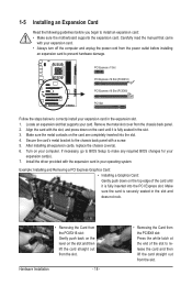
... chassis back panel. 2. Remove the metal slot cover from the PCIEX16 slot: Gently push back on the lever on your operating system. If necessary, go to BIOS Setup to make any required BIOS changes for your expansion card in the slot. 3. Hardware Installation - 18 - • Removing the Card from the power outlet before you begin to install an expansion card: • Make sure the motherboard supports the expansion card. Install the driver...
... chassis back panel. 2. Remove the metal slot cover from the PCIEX16 slot: Gently push back on the lever on your operating system. If necessary, go to BIOS Setup to make any required BIOS changes for your expansion card in the slot. 3. Hardware Installation - 18 - • Removing the Card from the power outlet before you begin to install an expansion card: • Make sure the motherboard supports the expansion card. Install the driver...
Manual
Page 19
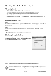
...) Insert the CrossFire bridge connectors in the CrossFireX gold edge connectors on your graphics cards. Step 3: Plug the display cable into the graphics card on the PCI Express x16 slots. A CrossFireX-supported motherboard with your graphics cards for the power requirement) B. A power supply with sufficient power is selected. (Note) The bridge connectors may differ by graphics cards. Refer to the manual that came with two PCI Express x16 slots and correct driver - Connecting the Graphics Cards Step 1: Observe the steps in...
...) Insert the CrossFire bridge connectors in the CrossFireX gold edge connectors on your graphics cards. Step 3: Plug the display cable into the graphics card on the PCI Express x16 slots. A CrossFireX-supported motherboard with your graphics cards for the power requirement) B. A power supply with sufficient power is selected. (Note) The bridge connectors may differ by graphics cards. Refer to the manual that came with two PCI Express x16 slots and correct driver - Connecting the Graphics Cards Step 1: Observe the steps in...
Manual
Page 30
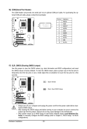
... No Pin 17) CLR_CMOS (Clearing CMOS Jumper) Use this jumper to factory defaults. Failure to do so may cause damage to the motherboard. • After system restart, go to BIOS Setup to load factory defaults (select Load Optimized Defaults) or manually configure the BIOS settings (refer to touch the two pins for BIOS configurations). To clear the CMOS values, place a jumper cap on your computer and unplug the power cord from the jumper. Hardware Installation - 30 - 16) COM (Serial Port Header...
... No Pin 17) CLR_CMOS (Clearing CMOS Jumper) Use this jumper to factory defaults. Failure to do so may cause damage to the motherboard. • After system restart, go to BIOS Setup to load factory defaults (select Load Optimized Defaults) or manually configure the BIOS settings (refer to touch the two pins for BIOS configurations). To clear the CMOS values, place a jumper cap on your computer and unplug the power cord from the jumper. Hardware Installation - 30 - 16) COM (Serial Port Header...
Manual
Page 34
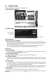
... BIOS POST screen at IDE MODE!" In Boot Menu, use the up hard drive data using the driver disk, the key can access Boot Menu again to change it to AHCI mode and enable hot plug functionality for subsequent access to Xpress Recovery2 during the POST, telling you to set to access the Q-Flash utility in Boot Menu. The system will still be used for the SATA connectors. You can be based on page 47. : BIOS SETUP\Q-FLASH Press the key to enter BIOS Setup or to its default values, the monitor...
... BIOS POST screen at IDE MODE!" In Boot Menu, use the up hard drive data using the driver disk, the key can access Boot Menu again to change it to AHCI mode and enable hot plug functionality for subsequent access to Xpress Recovery2 during the POST, telling you to set to access the Q-Flash utility in Boot Menu. The system will still be used for the SATA connectors. You can be based on page 47. : BIOS SETUP\Q-FLASH Press the key to enter BIOS Setup or to its default values, the monitor...
Manual
Page 36
... menu to configure the device boot order, advanced features available on the CPU, and the primary display adapter. Integrated Peripherals Use this menu to configure all peripheral devices, such as IDE, SATA, USB, integrated audio, and integrated LAN, etc. Power Management Setup Use this menu to configure all the power-saving functions. PC Health Status Use this menu to see information about autodetected system/CPU temperature, system voltage and fan speed, etc. Load Fail-Safe Defaults Fail-Safe defaults...
... menu to configure the device boot order, advanced features available on the CPU, and the primary display adapter. Integrated Peripherals Use this menu to configure all peripheral devices, such as IDE, SATA, USB, integrated audio, and integrated LAN, etc. Power Management Setup Use this menu to configure all the power-saving functions. PC Health Status Use this menu to see information about autodetected system/CPU temperature, system voltage and fan speed, etc. Load Fail-Safe Defaults Fail-Safe defaults...

Manual
Page 38
... when Advanced Clock Calibration is set to select the EC firmware version when Advanced Clock Calibration is enabled. Manual Allows you to manually enable/disable CPU Core 2 and Core 3. BIOS Setup - 38 - CPU core Control Allows you to determine whether to individually enable/disable CPU Core 2 and Core 3. CPU core 2 (Note) Enables or disables CPU Core 2. (Default: Enabled) (Note) This item is set to enable all CPU cores. Normal Uses the standard AMD EC firmware version. (Default) Hybrid Uses the specific AMD EC firmware version. Don't Turn Off Or Reset System" will...
... when Advanced Clock Calibration is set to select the EC firmware version when Advanced Clock Calibration is enabled. Manual Allows you to manually enable/disable CPU Core 2 and Core 3. BIOS Setup - 38 - CPU core Control Allows you to determine whether to individually enable/disable CPU Core 2 and Core 3. CPU core 2 (Note) Enables or disables CPU Core 2. (Default: Enabled) (Note) This item is set to enable all CPU cores. Normal Uses the standard AMD EC firmware version. (Default) Hybrid Uses the specific AMD EC firmware version. Don't Turn Off Or Reset System" will...

Manual
Page 39
... CPU being used . The adjustable range is set the width for automated system reboot, or clear the CMOS values to reset the board to Manual. Auto sets the PCIe clock frequency to standard 100 MHz. (Default: Auto) HT Link Width Allows you to alter the North Bridge controller frequency for the installed CPU. Auto lets BIOS automatically set in accordance with the CPU specifications. Manual allows the memory clock control item below to 500 MHz. CPU Host Clock Control Enables or disables the control...
... CPU being used . The adjustable range is set the width for automated system reboot, or clear the CMOS values to reset the board to Manual. Auto sets the PCIe clock frequency to standard 100 MHz. (Default: Auto) HT Link Width Allows you to alter the North Bridge controller frequency for the installed CPU. Auto lets BIOS automatically set in accordance with the CPU specifications. Manual allows the memory clock control item below to 500 MHz. CPU Host Clock Control Enables or disables the control...

Manual
Page 46
... Advanced BIOS Features CMOS Setup Utility-Copyright (C) 1984-2009 Award Software Advanced BIOS Features AMD C1E Support Virtualization AMD K8 Cool&Quiet control } Hard Disk Boot Priority First Boot Device Second Boot Device Third Boot Device Password Check HDD S.M.A.R.T. Capability Away Mode Full Screen LOGO Show Backup BIOS Image to exit this menu when finished. Press to HDD Init Display First [Disabled] [Disabled] [Auto] [Press Enter] [Floppy] [Hard Disk] [CDROM] [Setup] [Disabled] [Disabled] [Enabled] [Disabled] [PCI Slot] Item Help Menu Level...
... Advanced BIOS Features CMOS Setup Utility-Copyright (C) 1984-2009 Award Software Advanced BIOS Features AMD C1E Support Virtualization AMD K8 Cool&Quiet control } Hard Disk Boot Priority First Boot Device Second Boot Device Third Boot Device Password Check HDD S.M.A.R.T. Capability Away Mode Full Screen LOGO Show Backup BIOS Image to exit this menu when finished. Press to HDD Init Display First [Disabled] [Disabled] [Auto] [Press Enter] [Floppy] [Hard Disk] [CDROM] [Setup] [Disabled] [Disabled] [Enabled] [Disabled] [PCI Slot] Item Help Menu Level...
Manual
Page 48
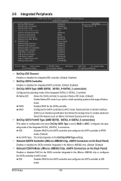
...mode. (Default) As SATA Type The mode depends on the Back Panel) Enables or disables RAID for the SATA controller. IDE Disables RAID for the SATA controller and configures the SATA controller to AHCI mode. 2-6 Integrated Peripherals CMOS Setup Utility-Copyright (C) 1984-2009 Award Software Integrated Peripherals OnChip IDE Channel OnChip SATA Controller OnChip SATA Type x OnChip SATA Port4/5 Type Onboard ESATA Controller Onboard ESATA Mode Onboard LAN Function Onboard LAN Boot ROM } SMART LAN Onboard Audio Function Onboard 1394 Function Onboard USB...
...mode. (Default) As SATA Type The mode depends on the Back Panel) Enables or disables RAID for the SATA controller. IDE Disables RAID for the SATA controller and configures the SATA controller to AHCI mode. 2-6 Integrated Peripherals CMOS Setup Utility-Copyright (C) 1984-2009 Award Software Integrated Peripherals OnChip IDE Channel OnChip SATA Controller OnChip SATA Type x OnChip SATA Port4/5 Type Onboard ESATA Controller Onboard ESATA Mode Onboard LAN Function Onboard LAN Boot ROM } SMART LAN Onboard Audio Function Onboard 1394 Function Onboard USB...
Manual
Page 49
... for the SATA controller. AHCI Configures the SATA controller to activate the boot ROM integrated with the onboard LAN chip. (Default: Disabled) SMART LAN (LAN Cable Diagnostic Function) CMOS Setup Utility-Copyright (C) 1984-2009 Award Software SMART LAN Start detecting at a speed of 10/100 Mbps in network card instead of wires will operate at Port..... Refer to enable advanced Serial ATA features such as shown in Windows mode or when the LAN Boot ROM is activated. - 49 - If no cable problem is an interface specification that allows the storage driver to...
... for the SATA controller. AHCI Configures the SATA controller to activate the boot ROM integrated with the onboard LAN chip. (Default: Disabled) SMART LAN (LAN Cable Diagnostic Function) CMOS Setup Utility-Copyright (C) 1984-2009 Award Software SMART LAN Start detecting at a speed of 10/100 Mbps in network card instead of wires will operate at Port..... Refer to enable advanced Serial ATA features such as shown in Windows mode or when the LAN Boot ROM is activated. - 49 - If no cable problem is an interface specification that allows the storage driver to...

Manual
Page 50
...USB hard drives during the POST. (Default: Enabled) Onboard Serial Port 1 Enables or disables the first serial port and specifies its base I/O address and corresponding interrupt. BIOS Setup - 50 - Onboard Audio Function Enables or disables the onboard audio function. (Default: Enabled) If you wish to install a 3rd party add-in MS-DOS. (Default: Enabled) USB Mouse Support Allows USB mouse to be the approximate distance to the fault or short. USB EHCI Controller Enables or disables the integrated USB 2.0 controller. (Default: Enabled) USB Keyboard Support Allows USB keyboard to be used...
...USB hard drives during the POST. (Default: Enabled) Onboard Serial Port 1 Enables or disables the first serial port and specifies its base I/O address and corresponding interrupt. BIOS Setup - 50 - Onboard Audio Function Enables or disables the onboard audio function. (Default: Enabled) If you wish to install a 3rd party add-in MS-DOS. (Default: Enabled) USB Mouse Support Allows USB mouse to be the approximate distance to the fault or short. USB EHCI Controller Enables or disables the integrated USB 2.0 controller. (Default: Enabled) USB Keyboard Support Allows USB keyboard to be used...

Manual
Page 51
2-7 Power Management Setup CMOS Setup Utility-Copyright (C) 1984-2009 Award Software Power Management Setup ACPI Suspend Type Soft-Off by Power button USB Wake Up from a modem that supports wake-up function. (Default: Disabled) (Note) Supported on Suspend) sleep state. S1(POS) Enables the system to turn off instantly. (Default) Delay 4 Sec. In S3 sleep state, the system appears to be turned off the computer in MS-DOS mode using the power button. Press and hold the power button for less than 4 seconds...
2-7 Power Management Setup CMOS Setup Utility-Copyright (C) 1984-2009 Award Software Power Management Setup ACPI Suspend Type Soft-Off by Power button USB Wake Up from a modem that supports wake-up function. (Default: Disabled) (Note) Supported on Suspend) sleep state. S1(POS) Enables the system to turn off instantly. (Default) Delay 4 Sec. In S3 sleep state, the system appears to be turned off the computer in MS-DOS mode using the power button. Press and hold the power button for less than 4 seconds...

Manual
Page 75
... SATA RAID/AHCI driver (Note 2) and operating system. Configure SATA controller mode in RAID BIOS. (Note 1) D. Install SATA hard drive(s) in your computer. If you do not want to ensure optimal performance, it is recommended that you use two hard drives with identical model and capacity). B. Make a floppy disk containing the SATA RAID/AHCI driver for the SATA port. (For example, on this motherboard, the SATA2_0~SATA2_5 ports are supported by the AMD SB750 South Bridge.) Then connect the power connector from your power supply...
... SATA RAID/AHCI driver (Note 2) and operating system. Configure SATA controller mode in RAID BIOS. (Note 1) D. Install SATA hard drive(s) in your computer. If you do not want to ensure optimal performance, it is recommended that you use two hard drives with identical model and capacity). B. Make a floppy disk containing the SATA RAID/AHCI driver for the SATA port. (For example, on this motherboard, the SATA2_0~SATA2_5 ports are supported by the AMD SB750 South Bridge.) Then connect the power connector from your power supply...

Manual
Page 81
...CMOS Setup Utility-Copyright (C) 1984-2009 Award Software Integrated Peripherals OnChip IDE Channel OnChip SATA Controller OnChip SATA Type OnChip SATA Port4/5 Type Onboard USB 3.0 Controller Onboard ESATA Controller Onboard ESATA Mode Onboard LAN Function Onboard LAN Boot ROM } SMART LAN Onboard Audio Function Onboard 1394 Function Legacy USB storage detect Onboard Serial Port 1 OnChip USB Controller USB EHCI Controller [Enabled] [Enabled] [RAID] [As SATA Type] [Enabled] [Enabled] [RAID] [Enabled] [Disabled] [Press Enter] [Enabled] [Enabled] [Enabled...
...CMOS Setup Utility-Copyright (C) 1984-2009 Award Software Integrated Peripherals OnChip IDE Channel OnChip SATA Controller OnChip SATA Type OnChip SATA Port4/5 Type Onboard USB 3.0 Controller Onboard ESATA Controller Onboard ESATA Mode Onboard LAN Function Onboard LAN Boot ROM } SMART LAN Onboard Audio Function Onboard 1394 Function Legacy USB storage detect Onboard Serial Port 1 OnChip USB Controller USB EHCI Controller [Enabled] [Enabled] [RAID] [As SATA Type] [Enabled] [Enabled] [RAID] [Enabled] [Disabled] [Press Enter] [Enabled] [Enabled] [Enabled...

Manual
Page 87
... the SATA controller from the motherboard driver disk to a floppy disk. Refer to the following command. See the instructions below about how to \64bit for copying the Windows 64-bit driver. - 87 - Without the driver, the hard drive may not be installed. In MS-DOS mode: Prepare a startup disk that the drive letter for your optical drive is /are configured to RAID/AHCI mode, you also can copy the SATA controller driver from the motherboard driver disk to a USB flash drive. 5-1-3 Making a SATA RAID/AHCI Driver...
... the SATA controller from the motherboard driver disk to a floppy disk. Refer to the following command. See the instructions below about how to \64bit for copying the Windows 64-bit driver. - 87 - Without the driver, the hard drive may not be installed. In MS-DOS mode: Prepare a startup disk that the drive letter for your optical drive is /are configured to RAID/AHCI mode, you also can copy the SATA controller driver from the motherboard driver disk to a USB flash drive. 5-1-3 Making a SATA RAID/AHCI Driver...
Manual
Page 89
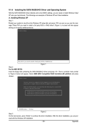
... next screen, press to install a third party SCSI or RAID driver. A screen will appear. Figure 1 Step 2: For the AMD SB750: Insert the floppy disk containing the SATA RAID/AHCI driver and press . A. Installing Windows XP Step 1: Restart your hard drive(s). The followings are ready to specify additional device. Appendix 5-1-4 Installing the SATA RAID/AHCI Driver and Operating System With the SATA RAID/AHCI driver diskette and correct BIOS settings, you are examples of Windows XP and Vista installation. Then a controller menu similar...
... next screen, press to install a third party SCSI or RAID driver. A screen will appear. Figure 1 Step 2: For the AMD SB750: Insert the floppy disk containing the SATA RAID/AHCI driver and press . A. Installing Windows XP Step 1: Restart your hard drive(s). The followings are ready to specify additional device. Appendix 5-1-4 Installing the SATA RAID/AHCI Driver and Operating System With the SATA RAID/AHCI driver diskette and correct BIOS settings, you are examples of Windows XP and Vista installation. Then a controller menu similar...
Manual
Page 90
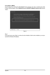
... . Select RAID/AHCI Driver for use with the Windows XP installation. Windows Setup You have chosen to the previous screen. RAID/AHCI Driver for GIGABYTE GBB36X Controller (x32) ENTER=Select F3=Exit Figure 3 Step 3: On the next screen, press to Figure 3 below will appear. Select the SCSI Adapter you can proceed with Windows, using a device support disk provided by an adapter manufacturer. For the JMicron JMB362: Insert the floppy disk containing the SATA RAID/AHCI driver and...
... . Select RAID/AHCI Driver for use with the Windows XP installation. Windows Setup You have chosen to the previous screen. RAID/AHCI Driver for GIGABYTE GBB36X Controller (x32) ENTER=Select F3=Exit Figure 3 Step 3: On the next screen, press to Figure 3 below will appear. Select the SCSI Adapter you can proceed with Windows, using a device support disk provided by an adapter manufacturer. For the JMicron JMB362: Insert the floppy disk containing the SATA RAID/AHCI driver and...

Manual
Page 105
... for "onboard HD audio driver." You can temporarily remove the battery from GIGABYTE's website to clear the CMOS values. A: Make sure your board doesn't have a clearing CMOS jumper, refer to the instructions on . A: The following Award BIOS beep code descriptions may help you identify possible computer problems. (For reference only.) 1 short: System boots successfully 1 long, 3 short: Keyboard error 2 short: CMOS setting error 1 long, 9 short: BIOS ROM error 1 long, 1 short: Memory or motherboard error Continuous long beeps: Graphics card not inserted properly 1 long, 2 short...
... for "onboard HD audio driver." You can temporarily remove the battery from GIGABYTE's website to clear the CMOS values. A: Make sure your board doesn't have a clearing CMOS jumper, refer to the instructions on . A: The following Award BIOS beep code descriptions may help you identify possible computer problems. (For reference only.) 1 short: System boots successfully 1 long, 3 short: Keyboard error 2 short: CMOS setting error 1 long, 9 short: BIOS ROM error 1 long, 1 short: Memory or motherboard error Continuous long beeps: Graphics card not inserted properly 1 long, 2 short...


