Manual
Page 1
GA-790XT-USB3 AM3 socket motherboard for AMD Phenom™ II processor/AMD Athlon™ II processor User's Manual Rev. 1001 12ME-790XTU3-1001R
GA-790XT-USB3 AM3 socket motherboard for AMD Phenom™ II processor/AMD Athlon™ II processor User's Manual Rev. 1001 12ME-790XTU3-1001R
Manual
Page 2
Motherboard GA-790XT-USB3 Dec. 21, 2009 Motherboard GA-790XT-USB3 Dec. 21, 2009
Motherboard GA-790XT-USB3 Dec. 21, 2009 Motherboard GA-790XT-USB3 Dec. 21, 2009
Manual
Page 3
...of the product, read the User's Manual. For product-related information, check on our website at: http://www.gigabyte.com.tw Identifying Your Motherboard Revision The revision number on our website. All rights reserved. For example, "REV: 1.0" means the revision ...of this : "REV: X.X." Disclaimer Information in the use GIGABYTE's unique features, read or download the information on/from the Support&Downloads\Motherboard\Technology Guide page on your motherboard revision before updating motherboard BIOS, drivers, or when looking for technical information. Copyright ©...
...of the product, read the User's Manual. For product-related information, check on our website at: http://www.gigabyte.com.tw Identifying Your Motherboard Revision The revision number on our website. All rights reserved. For example, "REV: 1.0" means the revision ...of this : "REV: X.X." Disclaimer Information in the use GIGABYTE's unique features, read or download the information on/from the Support&Downloads\Motherboard\Technology Guide page on your motherboard revision before updating motherboard BIOS, drivers, or when looking for technical information. Copyright ©...
Manual
Page 4
Table of Contents Box Contents...6 Optional Items...6 GA-790XT-USB3 Motherboard Layout 7 Block Diagram...8 Chapter 1 Hardware Installation 9 1-1 Installation Precautions 9 1-2 Product Specifications 10 1-3 Installing the CPU and CPU Cooler 13 1-3-1 Installing the CPU 13 1-3-2 Installing the CPU ...
Table of Contents Box Contents...6 Optional Items...6 GA-790XT-USB3 Motherboard Layout 7 Block Diagram...8 Chapter 1 Hardware Installation 9 1-1 Installation Precautions 9 1-2 Product Specifications 10 1-3 Installing the CPU and CPU Cooler 13 1-3-1 Installing the CPU 13 1-3-2 Installing the CPU ...
Manual
Page 6
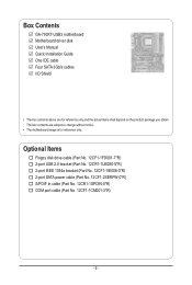
...Part No. 12CF1-2SERPW-0*R) S/PDIF In cable (Part No. 12CR1-1SPDIN-0*R) COM port cable (Part No. 12CF1-1CM001-3*R) - 6 - Box Contents GA-790XT-USB3 motherboard Motherboard driver disk User's Manual Quick Installation Guide One IDE cable Four SATA 3Gb/s cables I/O Shield • The box contents above are subject to change ...without notice. • The motherboard image is for reference only and the actual items shall depend on the product package you obtain. The box contents are for reference only...
...Part No. 12CF1-2SERPW-0*R) S/PDIF In cable (Part No. 12CR1-1SPDIN-0*R) COM port cable (Part No. 12CF1-1CM001-3*R) - 6 - Box Contents GA-790XT-USB3 motherboard Motherboard driver disk User's Manual Quick Installation Guide One IDE cable Four SATA 3Gb/s cables I/O Shield • The box contents above are subject to change ...without notice. • The motherboard image is for reference only and the actual items shall depend on the product package you obtain. The box contents are for reference only...
Manual
Page 7
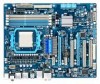
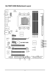
GA-790XT-USB3 Motherboard Layout KB_MS CPU_FAN RCA_SPDIF ATX_12V USB_1394_ESATA2 USB_1394_ESATA1 Socket AM3 PWR_FAN ATX R_USB USB30_LAN AUDIO NEC JMB362 F_AUDIO PCIEX1_1 AMD 790X IDE RTL8111D PCIEX16 IT8720 DDR3_1 DDR3_2 DDR3_3 DDR3_4 CD_IN CODEC PCIEX1_2 BAT PCI1 CLR_CMOS GA-790XT-USB3 SPDIF_IN PCIEX8 SPDIF_OUT PCI2 TSB43AB23 AMD SB750 B_BIOS M_BIOS SATA2_4 SATA2_5 SATA2_2 SATA2_3 SATA2_0 SATA2_1 PCI3 COM F_USB2 SYS_FAN2 F_PANEL SYS_FAN1 FDD F_1394 F_USB1 - 7 -
GA-790XT-USB3 Motherboard Layout KB_MS CPU_FAN RCA_SPDIF ATX_12V USB_1394_ESATA2 USB_1394_ESATA1 Socket AM3 PWR_FAN ATX R_USB USB30_LAN AUDIO NEC JMB362 F_AUDIO PCIEX1_1 AMD 790X IDE RTL8111D PCIEX16 IT8720 DDR3_1 DDR3_2 DDR3_3 DDR3_4 CD_IN CODEC PCIEX1_2 BAT PCI1 CLR_CMOS GA-790XT-USB3 SPDIF_IN PCIEX8 SPDIF_OUT PCI2 TSB43AB23 AMD SB750 B_BIOS M_BIOS SATA2_4 SATA2_5 SATA2_2 SATA2_3 SATA2_0 SATA2_1 PCI3 COM F_USB2 SYS_FAN2 F_PANEL SYS_FAN1 FDD F_1394 F_USB1 - 7 -

Manual
Page 9
...the product, please verify that all cables and power connectors of electrostatic discharge (ESD). Chapter 1 Hardware Installation 1-1 Installation Precautions The motherboard contains numerous delicate electronic circuits and components which can lead to damage to system components as well as physical harm to the user....system on an uneven surface. • Do not place the computer system in a high-temperature environment. • Turning on the motherboard, make sure they are uncertain about any metal leads or connectors. • It is best to wear an electrostatic discharge (ESD)...
...the product, please verify that all cables and power connectors of electrostatic discharge (ESD). Chapter 1 Hardware Installation 1-1 Installation Precautions The motherboard contains numerous delicate electronic circuits and components which can lead to damage to system components as well as physical harm to the user....system on an uneven surface. • Do not place the computer system in a high-temperature environment. • Turning on the motherboard, make sure they are uncertain about any metal leads or connectors. • It is best to wear an electrostatic discharge (ESD)...

Manual
Page 12
... (Note 1) Due to Windows 32-bit operating system limitation, when more than 4 GB of physical memory is to install it in EasyTune may differ by motherboard model. The PCIEX8 slot shares bandwidth with a PCI Express graphics card, the PCIEX16 slot will operate at up to x8 mode. (Note 4) Whether the CPU...
... (Note 1) Due to Windows 32-bit operating system limitation, when more than 4 GB of physical memory is to install it in EasyTune may differ by motherboard model. The PCIEX8 slot shares bandwidth with a PCI Express graphics card, the PCIEX16 slot will operate at up to x8 mode. (Note 4) Whether the CPU...

Manual
Page 13
... the CPU socket.) • Apply an even and thin layer of thermal grease on the computer if the CPU cooler is not recommended that the motherboard supports the CPU. (Go to your hardware specifications including the CPU, graphics card, memory, hard drive, etc. 1-3-1 Installing the CPU A. A Small ...system bus frequency be inserted if oriented incorrectly. (Or you wish to set beyond the standard specifications, please do so according to GIGABYTE's website for the peripherals. Locate the pin one of the Socket AM3 Socket A Small Triangle Marking Denotes CPU Pin One AM3 CPU - 13...
... the CPU socket.) • Apply an even and thin layer of thermal grease on the computer if the CPU cooler is not recommended that the motherboard supports the CPU. (Go to your hardware specifications including the CPU, graphics card, memory, hard drive, etc. 1-3-1 Installing the CPU A. A Small ...system bus frequency be inserted if oriented incorrectly. (Or you wish to set beyond the standard specifications, please do so according to GIGABYTE's website for the peripherals. Locate the pin one of the Socket AM3 Socket A Small Triangle Marking Denotes CPU Pin One AM3 CPU - 13...

Manual
Page 14
... CPU, lowering the locking lever and latching it into the socket. Hardware Installation - 14 - Follow the steps below to correctly install the CPU into the motherboard CPU socket. • Before installing the CPU, make sure to turn off the computer and unplug the power cord from the power outlet to prevent...
... CPU, lowering the locking lever and latching it into the socket. Hardware Installation - 14 - Follow the steps below to correctly install the CPU into the motherboard CPU socket. • Before installing the CPU, make sure to turn off the computer and unplug the power cord from the power outlet to prevent...

Manual
Page 15
... cooler.) Step 5: Finally, attach the power connector of the CPU cooler to correctly install the CPU cooler on the CPU. (The following procedure uses the GIGABYTE cooler as the example.) Step 1: Apply an even and thin layer of thermal grease on the surface of the retention frame. 1-3-2 Installing the CPU Cooler...
... cooler.) Step 5: Finally, attach the power connector of the CPU cooler to correctly install the CPU cooler on the CPU. (The following procedure uses the GIGABYTE cooler as the example.) Step 1: Apply an even and thin layer of thermal grease on the surface of the retention frame. 1-3-2 Installing the CPU Cooler...

Manual
Page 16
...latest memory support list.) • Always turn off the computer and unplug the power cord from the power outlet before installing the memory to GIGABYTE's website for optimum performance. DS/SS DS/SS Four Modules DS/SS DS/SS DS/SS DS/SS (SS=Single-Sided, DS=Double-... Dual Channel mode with two or four memory modules, it is recommended that the motherboard supports the memory. If you begin to insert the memory, switch the direction. 1-4-1 Dual Channel Memory Configuration This motherboard provides four DDR3 memory sockets and supports Dual Channel Technology. The four DDR3 memory ...
...latest memory support list.) • Always turn off the computer and unplug the power cord from the power outlet before installing the memory to GIGABYTE's website for optimum performance. DS/SS DS/SS Four Modules DS/SS DS/SS DS/SS DS/SS (SS=Single-Sided, DS=Double-... Dual Channel mode with two or four memory modules, it is recommended that the motherboard supports the memory. If you begin to insert the memory, switch the direction. 1-4-1 Dual Channel Memory Configuration This motherboard provides four DDR3 memory sockets and supports Dual Channel Technology. The four DDR3 memory ...

Manual
Page 17
..., make sure to turn off the computer and unplug the power cord from the power outlet to prevent damage to install DDR3 DIMMs on this motherboard. Follow the steps below to correctly install your fingers on the top edge of the memory module.
..., make sure to turn off the computer and unplug the power cord from the power outlet to prevent damage to install DDR3 DIMMs on this motherboard. Follow the steps below to correctly install your fingers on the top edge of the memory module.
Manual
Page 18
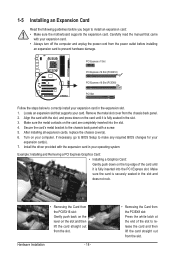
... in the expansion slot. 1. Remove the metal slot cover from the power outlet before you begin to install an expansion card: • Make sure the motherboard supports the expansion card. Install the driver provided with your card. Example: Installing and Removing a PCI Express Graphics Card: • Installing a Graphics Card: Gently push...
... in the expansion slot. 1. Remove the metal slot cover from the power outlet before you begin to install an expansion card: • Make sure the motherboard supports the expansion card. Install the driver provided with your card. Example: Installing and Removing a PCI Express Graphics Card: • Installing a Graphics Card: Gently push...
Manual
Page 19
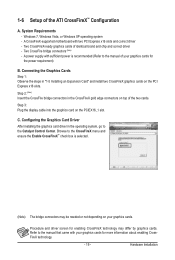
... to the Catalyst Control Center. Two CrossFire bridge connectors (Note) - A power supply with two PCI Express x16 slots and correct driver - System Requirements - A CrossFireX-supported motherboard with sufficient power is selected. (Note) The bridge connectors may differ by graphics cards. Windows 7, Windows Vista, or Windows XP operating system - Configuring the Graphics...
... to the Catalyst Control Center. Two CrossFire bridge connectors (Note) - A power supply with two PCI Express x16 slots and correct driver - System Requirements - A CrossFireX-supported motherboard with sufficient power is selected. (Note) The bridge connectors may differ by graphics cards. Windows 7, Windows Vista, or Windows XP operating system - Configuring the Graphics...
Manual
Page 20
... port to Chapter 5, "Configuring SATA Hard Drive(s)," for an IEEE 1394a device. Use this feature, ensure that your device and then remove it from the motherboard. • When removing the cable, pull it side to side to an external audio system that supports digital optical audio. Refer to connect an external...
... port to Chapter 5, "Configuring SATA Hard Drive(s)," for an IEEE 1394a device. Use this feature, ensure that your device and then remove it from the motherboard. • When removing the cable, pull it side to side to an external audio system that supports digital optical audio. Refer to connect an external...
Manual
Page 22
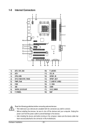
... devices and your devices are compliant with the connectors you wish to connect. • Before installing the devices, be sure to the connector on the motherboard.
... devices and your devices are compliant with the connectors you wish to connect. • Before installing the devices, be sure to the connector on the motherboard.

Manual
Page 23
...CPU. Hardware Installation Before connecting the power connector, first make sure the power supply is turned off and all the components on the motherboard. Do not insert the power supply cables into pins under the protective covers when using a power supply providing a 2x4 12V and ...a 2x12 power connector, remove the protective covers from the 12V power connector and the main power connector on the motherboard. The power connector possesses a foolproof design. 1/2) ATX_12V_2X4/ATX (2x4 12V Power Connector and 2x12 Main Power Connector) With the use of the...
...CPU. Hardware Installation Before connecting the power connector, first make sure the power supply is turned off and all the components on the motherboard. Do not insert the power supply cables into pins under the protective covers when using a power supply providing a 2x4 12V and ...a 2x12 power connector, remove the protective covers from the 12V power connector and the main power connector on the motherboard. The power connector possesses a foolproof design. 1/2) ATX_12V_2X4/ATX (2x4 12V Power Connector and 2x12 Main Power Connector) With the use of the...
Manual
Page 24
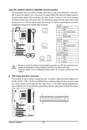
... pin 1 of floppy disk drives supported are not configuration jumper blocks. The types of the connector and the floppy disk drive cable. The motherboard supports CPU fan speed control, which requires the use of the cable is recom- Definition 1 CPU_FAN 1 GND 2 +12V / Speed Control... +12V / Speed Control 3 Sense 4 Reserve 1 1 SYS_FAN2 PWR_FAN SYS_FAN2/PWR_FAN: Pin No. 3/4/5) CPU_FAN/SYS_FAN1/SYS_FAN2/PWR_FAN (Fan Headers) The motherboard has a 4-pin CPU fan header (CPU_FAN), a 3-pin (SYS_FAN2) and a 4-pin (SYS_ FAN1) system fan headers, and a 3-pin power fan header (PWR_FAN).
... pin 1 of floppy disk drives supported are not configuration jumper blocks. The types of the connector and the floppy disk drive cable. The motherboard supports CPU fan speed control, which requires the use of the cable is recom- Definition 1 CPU_FAN 1 GND 2 +12V / Speed Control... +12V / Speed Control 3 Sense 4 Reserve 1 1 SYS_FAN2 PWR_FAN SYS_FAN2/PWR_FAN: Pin No. 3/4/5) CPU_FAN/SYS_FAN1/SYS_FAN2/PWR_FAN (Fan Headers) The motherboard has a 4-pin CPU fan header (CPU_FAN), a 3-pin (SYS_FAN2) and a 4-pin (SYS_ FAN1) system fan headers, and a 3-pin power fan header (PWR_FAN).

Manual
Page 27
... Audio Header) The front panel audio header supports Intel High Definition audio (HD) and AC'97 audio. Incorrect connection between the module connector and the motherboard header will be present on each wire instead of a single plug. Definition 1 CD-L 1 2 GND 3 GND 4 CD-R - 27 - You may ... optical drive to the header. For information about connecting the front panel audio module that has separated connectors on both of the motherboard header. Make sure the wire assignments of the module connector match the pin assignments of the front and back panel audio connections simultaneously...
... Audio Header) The front panel audio header supports Intel High Definition audio (HD) and AC'97 audio. Incorrect connection between the module connector and the motherboard header will be present on each wire instead of a single plug. Definition 1 CD-L 1 2 GND 3 GND 4 CD-R - 27 - You may ... optical drive to the header. For information about connecting the front panel audio module that has separated connectors on both of the motherboard header. Make sure the wire assignments of the module connector match the pin assignments of the front and back panel audio connections simultaneously...


