Manual
Page 10
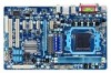
... Phenom™ II processor/ AMD Athlon™ II processor (Go to GIGABYTE's website for the latest CPU support list.) Hyper Transport Bus 5200 MT/s Chipset Memory Audio North Bridge: AMD 770 South Bridge: AMD SB710 2 x 1.5V DDR3 DIMM sockets supporting up to 8 GB of system memory (Note 1) Dual channel...
... Phenom™ II processor/ AMD Athlon™ II processor (Go to GIGABYTE's website for the latest CPU support list.) Hyper Transport Bus 5200 MT/s Chipset Memory Audio North Bridge: AMD 770 South Bridge: AMD SB710 2 x 1.5V DDR3 DIMM sockets supporting up to 8 GB of system memory (Note 1) Dual channel...

Manual
Page 11
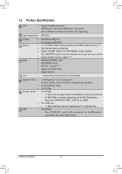
...pin ATX main power connector w 1 x 4-pin ATX 12V power connector w 1 x floppy disk drive connector w 1 x IDE connector w 6 x SATA 3Gb/s connectors w 1 x CPU fan header w 2 x system fan headers w 1 x power fan header w 1 x front panel header w 1 x front panel audio header w 1 x CD In connector w 1...w w w w System voltage detection CPU/System temperature detection CPU/System/Power fan speed detection CPU overheating warning CPU/System/Power fan fail warning CPU/System fan speed control (Note 4) 2 x 16 Mbit flash Use of licensed AWARD BIOS Support for DualBIOS™ PnP 1.0a, ...
...pin ATX main power connector w 1 x 4-pin ATX 12V power connector w 1 x floppy disk drive connector w 1 x IDE connector w 6 x SATA 3Gb/s connectors w 1 x CPU fan header w 2 x system fan headers w 1 x power fan header w 1 x front panel header w 1 x front panel audio header w 1 x CD In connector w 1...w w w w System voltage detection CPU/System temperature detection CPU/System/Power fan speed detection CPU overheating warning CPU/System/Power fan fail warning CPU/System fan speed control (Note 4) 2 x 16 Mbit flash Use of licensed AWARD BIOS Support for DualBIOS™ PnP 1.0a, ...
Manual
Page 12
..., when more than 4 GB of physical memory is installed, the actual memory size displayed will be less than 4 GB. (Note 2) Use of a CPU that supports ECC is required if you wish to install ECC memory. (Note 3) To enable 7.1-channel audio, you have to use an HD front panel audio module... and enable the multi-channel audio feature through the audio driver. (Note 4) Whether the CPU/system fan speed control function is supported will depend on the CPU/system cooler you install. (Note 5) Available functions in EasyTune may differ by motherboard model. (Note 6) Due to the...
..., when more than 4 GB of physical memory is installed, the actual memory size displayed will be less than 4 GB. (Note 2) Use of a CPU that supports ECC is required if you wish to install ECC memory. (Note 3) To enable 7.1-channel audio, you have to use an HD front panel audio module... and enable the multi-channel audio feature through the audio driver. (Note 4) Whether the CPU/system fan speed control function is supported will depend on the CPU/system cooler you install. (Note 5) Available functions in EasyTune may differ by motherboard model. (Note 6) Due to the...
Manual
Page 13
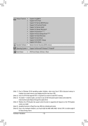
... specifications since it does not meet the standard requirements for the latest CPU support list.) • Always turn off the computer and unplug the power cord from the power outlet before installing the CPU to prevent hardware damage. • Locate the pin one (denoted by...computer if the CPU cooler is not recommended that the motherboard supports the CPU. (Go to your hardware specifications including the CPU, graphics card, memory, hard drive, etc. 1-3-1 Installing the CPU A. If you wish to set beyond the standard specifications, please do so according to GIGABYTE's website for...
... specifications since it does not meet the standard requirements for the latest CPU support list.) • Always turn off the computer and unplug the power cord from the power outlet before installing the CPU to prevent hardware damage. • Locate the pin one (denoted by...computer if the CPU cooler is not recommended that the motherboard supports the CPU. (Go to your hardware specifications including the CPU, graphics card, memory, hard drive, etc. 1-3-1 Installing the CPU A. If you wish to set beyond the standard specifications, please do so according to GIGABYTE's website for...
Manual
Page 16
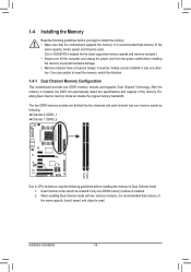
...you are divided into two channels and each channel has one memory socket as following: Channel 0: DDR3_1 Channel 1: DDR3_2 DDR3_1 DDR3_2 Due to CPU limitations, read the following guidelines before you begin to prevent hardware damage. • Memory modules have a foolproof design. When enabling Dual Channel... before installing the memory in only one direction. It is installed. 2. A memory module can be used . (Go to GIGABYTE's website for the latest supported memory speeds and memory modules.) • Always turn off the computer and unplug the power cord from the power outlet before ...
...you are divided into two channels and each channel has one memory socket as following: Channel 0: DDR3_1 Channel 1: DDR3_2 DDR3_1 DDR3_2 Due to CPU limitations, read the following guidelines before you begin to prevent hardware damage. • Memory modules have a foolproof design. When enabling Dual Channel... before installing the memory in only one direction. It is installed. 2. A memory module can be used . (Go to GIGABYTE's website for the latest supported memory speeds and memory modules.) • Always turn off the computer and unplug the power cord from the power outlet before ...

Manual
Page 23
The motherboard supports CPU fan speed control, which requires the use of floppy disk drives supported are not configuration jumper blocks. Definition 1 SYS_FAN2 PWR_FAN 1 GND 2 +12V 3 Sense • Be sure to connect fan cables to the ... 2 3 4 Definition GND +12V / Speed Control Sense Reserve 1 SYS_FAN2/PWR_FAN: Pin No. 3/4/5) CPU_FAN / SYS_FAN1 / SYS_FAN2 / PWR_FAN (Fan Headers) The motherboard has a 4-pin CPU fan header (CPU_FAN), a 4-pin (SYS_FAN1) and one 3-pin (SYS_ FAN2) system fan headers, and a 3-pin power fan header (PWR_FAN). Most fan headers possess a foolproof insertion...
The motherboard supports CPU fan speed control, which requires the use of floppy disk drives supported are not configuration jumper blocks. Definition 1 SYS_FAN2 PWR_FAN 1 GND 2 +12V 3 Sense • Be sure to connect fan cables to the ... 2 3 4 Definition GND +12V / Speed Control Sense Reserve 1 SYS_FAN2/PWR_FAN: Pin No. 3/4/5) CPU_FAN / SYS_FAN1 / SYS_FAN2 / PWR_FAN (Fan Headers) The motherboard has a 4-pin CPU fan header (CPU_FAN), a 4-pin (SYS_FAN1) and one 3-pin (SYS_ FAN2) system fan headers, and a 3-pin power fan header (PWR_FAN). Most fan headers possess a foolproof insertion...
Manual
Page 35
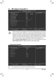
... Advanced Clock Calibration x Value (All Cores) x Value (Core 0) x Value (Core 1) x Value (Core 2) x Value (Core 3) CPU core Control x CPU core 0 x CPU core 1 (Note) x CPU core 2 (Note) x CPU core 3 (Note) [Normal] [Disabled] -2% -2% -2% -2% -2% [Auto] Enabled Enabled Enabled Enabled Item Help Menu Level ... item appears only if you made is dependent on your overall system configurations. This page is recommended that supports this occurs, clear the CMOS values and reset the board to default values.) • When the System Voltage...
... Advanced Clock Calibration x Value (All Cores) x Value (Core 0) x Value (Core 1) x Value (Core 2) x Value (Core 3) CPU core Control x CPU core 0 x CPU core 1 (Note) x CPU core 2 (Note) x CPU core 3 (Note) [Normal] [Disabled] -2% -2% -2% -2% -2% [Auto] Enabled Enabled Enabled Enabled Item Help Menu Level ... item appears only if you made is dependent on your overall system configurations. This page is recommended that supports this occurs, clear the CMOS values and reset the board to default values.) • When the System Voltage...

Manual
Page 37
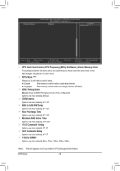
... BIOS automatically set the memory clock. DRAM Configuration CMOS Setup Utility-Copyright (C) 1984-2010 Award Software DRAM Configuration CPU Host Clock Control x CPU Frequency(MHz) Set Memory Clock x Memory Clock DCTs Mode (Note) DDR3 Timing Items x CAS# latency ... 1T/2T Command Timing x TwTr Command Delay x Trfc0 for DIMM1 x Trfc2 for the HT Link between the CPU and chipset. Set Memory Clock Determines whether to manually set the memory clock as required. X5.33 Sets Memory ... X4.00. PCIE Clock(MHz) Allows you install a CPU that supports this feature. - 37 -
... BIOS automatically set the memory clock. DRAM Configuration CMOS Setup Utility-Copyright (C) 1984-2010 Award Software DRAM Configuration CPU Host Clock Control x CPU Frequency(MHz) Set Memory Clock x Memory Clock DCTs Mode (Note) DDR3 Timing Items x CAS# latency ... 1T/2T Command Timing x TwTr Command Delay x Trfc0 for DIMM1 x Trfc2 for the HT Link between the CPU and chipset. Set Memory Clock Determines whether to manually set the memory clock as required. X5.33 Sets Memory ... X4.00. PCIE Clock(MHz) Allows you install a CPU that supports this feature. - 37 -
Manual
Page 38
... Select F5: Previous Values +/-/PU/PD: Value F10: Save F6: Fail-Safe Defaults ESC: Exit F1: General Help F7: Optimized Defaults CPU Host Clock Control, CPU Frequency (MHz), Set Memory Clock, Memory Clock The settings under the four items above are : Auto (default), 4T~12T. Trfc0 for DIMM1...) DDR3 Timing Items Manual allows all DDR2 Timing items below to single dual-channel. BIOS Setup - 38 - DCTs Mode (Note) Allows you install a CPU that supports this feature. RAS to CAS R/W Delay Options are : Auto (default), 1T, 2T. Minimum RAS Active Time Options are: Auto (default), 15T~30T....
... Select F5: Previous Values +/-/PU/PD: Value F10: Save F6: Fail-Safe Defaults ESC: Exit F1: General Help F7: Optimized Defaults CPU Host Clock Control, CPU Frequency (MHz), Set Memory Clock, Memory Clock The settings under the four items above are : Auto (default), 4T~12T. Trfc0 for DIMM1...) DDR3 Timing Items Manual allows all DDR2 Timing items below to single dual-channel. BIOS Setup - 38 - DCTs Mode (Note) Allows you install a CPU that supports this feature. RAS to CAS R/W Delay Options are : Auto (default), 1T, 2T. Minimum RAS Active Time Options are: Auto (default), 15T~30T....

Manual
Page 39
... adjustable range is from 1.100V to 2.400V. NB Voltage Control Allows you install a CPU that supports this feature. - 39 - Normal CPU Vcore Displays the normal operating voltage of the memory to your CPU or reduce the useful life of the memory. Bank Interleaving Enables or disables memory bank interleaving. Auto lets the BIOS automatically...
... adjustable range is from 1.100V to 2.400V. NB Voltage Control Allows you install a CPU that supports this feature. - 39 - Normal CPU Vcore Displays the normal operating voltage of the memory to your CPU or reduce the useful life of the memory. Bank Interleaving Enables or disables memory bank interleaving. Auto lets the BIOS automatically...
Manual
Page 42
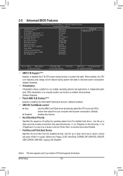
... +/-/PU/PD: Value F10: Save F6: Fail-Safe Defaults ESC: Exit F1: General Help F7: Optimized Defaults AMD C1E Support (Note) Enables or disables the C1E CPU power-saving function in independent partitions. Use the up or down arrow key to select a device and press to move it up... Disk, CDROM, ZIP, USB-FDD, USB-ZIP, USB-CDROM, USB-HDD, Legacy LAN, Disabled. (Note) This item appears only if you install a CPU that supports this menu when finished. First/Second/Third Boot Device Specifies the boot order from the installed hard drives. BIOS Setup - 42 - Use the up or...
... +/-/PU/PD: Value F10: Save F6: Fail-Safe Defaults ESC: Exit F1: General Help F7: Optimized Defaults AMD C1E Support (Note) Enables or disables the C1E CPU power-saving function in independent partitions. Use the up or down arrow key to select a device and press to move it up... Disk, CDROM, ZIP, USB-FDD, USB-ZIP, USB-CDROM, USB-HDD, Legacy LAN, Disabled. (Note) This item appears only if you install a CPU that supports this menu when finished. First/Second/Third Boot Device Specifies the boot order from the installed hard drives. BIOS Setup - 42 - Use the up or...
Manual
Page 66
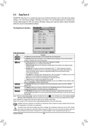
...Grayed-out area(s) indicates that the item is not configurable or the function is not supported. Incorrectly doing overclock/overvoltage may differ by motherboard model. Smart Fan allows the CPU fan speed to be sure to click Set for these components. The Memory tab provides... is configurable only in Easy mode/Advanced mode, be changed linearly based on the installed CPU and motherboard. You can select memory module on the installed memory module(s). 4-3 EasyTune 6 GIGABYTE's EasyTune 6 is a simple and easy-to-use interface that allows users to fine-...
...Grayed-out area(s) indicates that the item is not configurable or the function is not supported. Incorrectly doing overclock/overvoltage may differ by motherboard model. Smart Fan allows the CPU fan speed to be sure to click Set for these components. The Memory tab provides... is configurable only in Easy mode/Advanced mode, be changed linearly based on the installed CPU and motherboard. You can select memory module on the installed memory module(s). 4-3 EasyTune 6 GIGABYTE's EasyTune 6 is a simple and easy-to-use interface that allows users to fine-...
Manual
Page 95
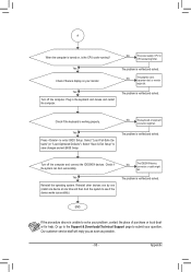
Yes Check if there is display on , is the CPU cooler running? Yes Turn off the computer and connect the IDE/SATA devices. Yes Press to see if the device works successfully). Turn off the ... "Load Fail-Safe Defaults" (or "Load Optimized Defaults"). A When the computer is turned on your monitor. No The power supply, CPU or CPU socket might fail. Or go to the Support & Downloads\Technical Support page to save changes and exit BIOS Setup. Appendix No The keyboard or keyboard connector might fail. END If the...
Yes Check if there is display on , is the CPU cooler running? Yes Turn off the computer and connect the IDE/SATA devices. Yes Press to see if the device works successfully). Turn off the ... "Load Fail-Safe Defaults" (or "Load Optimized Defaults"). A When the computer is turned on your monitor. No The power supply, CPU or CPU socket might fail. Or go to the Support & Downloads\Technical Support page to save changes and exit BIOS Setup. Appendix No The keyboard or keyboard connector might fail. END If the...

